US6134001A - Fluid diagnostic technique - Google Patents
Fluid diagnostic technique Download PDFInfo
- Publication number
- US6134001A US6134001A US09/280,977 US28097799A US6134001A US 6134001 A US6134001 A US 6134001A US 28097799 A US28097799 A US 28097799A US 6134001 A US6134001 A US 6134001A
- Authority
- US
- United States
- Prior art keywords
- spark
- fluid
- laser
- laser induced
- diagnostic technique
- Prior art date
- Legal status (The legal status is an assumption and is not a legal conclusion. Google has not performed a legal analysis and makes no representation as to the accuracy of the status listed.)
- Expired - Lifetime
Links
- 239000012530 fluid Substances 0.000 title claims abstract description 47
- 238000012631 diagnostic technique Methods 0.000 title claims abstract description 28
- 230000015556 catabolic process Effects 0.000 claims abstract description 45
- 230000003111 delayed effect Effects 0.000 claims abstract description 24
- 150000002500 ions Chemical class 0.000 claims abstract description 9
- 238000005215 recombination Methods 0.000 claims abstract description 8
- 230000006798 recombination Effects 0.000 claims abstract description 8
- 229910052779 Neodymium Inorganic materials 0.000 claims description 7
- QEFYFXOXNSNQGX-UHFFFAOYSA-N neodymium atom Chemical compound [Nd] QEFYFXOXNSNQGX-UHFFFAOYSA-N 0.000 claims description 7
- 238000005259 measurement Methods 0.000 abstract description 5
- 230000000414 obstructive effect Effects 0.000 abstract 1
- 238000000034 method Methods 0.000 description 6
- ATUOYWHBWRKTHZ-UHFFFAOYSA-N Propane Chemical compound CCC ATUOYWHBWRKTHZ-UHFFFAOYSA-N 0.000 description 2
- 238000009529 body temperature measurement Methods 0.000 description 2
- 230000003287 optical effect Effects 0.000 description 2
- 230000001360 synchronised effect Effects 0.000 description 2
- 238000000827 velocimetry Methods 0.000 description 2
- 238000009530 blood pressure measurement Methods 0.000 description 1
- 238000009792 diffusion process Methods 0.000 description 1
- 239000007788 liquid Substances 0.000 description 1
- 238000010899 nucleation Methods 0.000 description 1
- 239000002245 particle Substances 0.000 description 1
- 230000002085 persistent effect Effects 0.000 description 1
- 239000001294 propane Substances 0.000 description 1
- 238000001454 recorded image Methods 0.000 description 1
- 239000000523 sample Substances 0.000 description 1
- 230000003068 static effect Effects 0.000 description 1
Images


Classifications
-
- G—PHYSICS
- G01—MEASURING; TESTING
- G01K—MEASURING TEMPERATURE; MEASURING QUANTITY OF HEAT; THERMALLY-SENSITIVE ELEMENTS NOT OTHERWISE PROVIDED FOR
- G01K11/00—Measuring temperature based upon physical or chemical changes not covered by groups G01K3/00, G01K5/00, G01K7/00 or G01K9/00
-
- G—PHYSICS
- G01—MEASURING; TESTING
- G01N—INVESTIGATING OR ANALYSING MATERIALS BY DETERMINING THEIR CHEMICAL OR PHYSICAL PROPERTIES
- G01N21/00—Investigating or analysing materials by the use of optical means, i.e. using sub-millimetre waves, infrared, visible or ultraviolet light
- G01N21/62—Systems in which the material investigated is excited whereby it emits light or causes a change in wavelength of the incident light
- G01N21/71—Systems in which the material investigated is excited whereby it emits light or causes a change in wavelength of the incident light thermally excited
- G01N21/718—Laser microanalysis, i.e. with formation of sample plasma
-
- G—PHYSICS
- G01—MEASURING; TESTING
- G01P—MEASURING LINEAR OR ANGULAR SPEED, ACCELERATION, DECELERATION, OR SHOCK; INDICATING PRESENCE, ABSENCE, OR DIRECTION, OF MOVEMENT
- G01P5/00—Measuring speed of fluids, e.g. of air stream; Measuring speed of bodies relative to fluids, e.g. of ship, of aircraft
- G01P5/18—Measuring speed of fluids, e.g. of air stream; Measuring speed of bodies relative to fluids, e.g. of ship, of aircraft by measuring the time taken to traverse a fixed distance
- G01P5/20—Measuring speed of fluids, e.g. of air stream; Measuring speed of bodies relative to fluids, e.g. of ship, of aircraft by measuring the time taken to traverse a fixed distance using particles entrained by a fluid stream
Definitions
- the present invention relates to fluid diagnostic techniques and in particular to non-obtrusive diagnostic techniques which enable the measurement of different parameters in a gas flow.
- Optical techniques are desirable for the measurement of fluid parameters as other instruments, such as physical type probes, disturb the flow at precisely the location of measurement.
- the present invention seeks to provide a non-intrusive diagnostic technique which utilizes the laser induced breakdown phenomenon.
- a fluid diagnostic technique comprises the steps of focusing a laser in the fluid to generate a laser induced breakdown spark, measuring the characteristics of the initial laser induced breakdown spark and comparing the characteristics of the initial laser induced spark to the characteristics of a delayed image of the spark, formed by light emission due to recombination and excited molecules and ions generated by the laser induced spark, differences between the initial and delayed images being used to diagnose characteristics of the fluid.
- a fluid diagnostic technique for measuring the velocity of a fluid flow comprises the steps of focusing a laser in the fluid to generate an initial laser induced breakdown spark, measuring the center of the initial laser induced breakdown spark and comparing the center of the initial spark to the center of a delayed image of the spark formed by light emission due to recombination and exited molecules and ions generated by the initial laser induced spark, the shift in position of the center of the initial spark and the center of the delayed image of the spark being used to calculate the velocity of the fluid flow.
- a fluid diagnostic technique for measuring the temperature of a fluid comprises the steps of focusing a laser in a fluid to generate an initial laser induced breakdown spark, comparing the initial laser induced breakdown spark to a delayed image of the spark formed by the light emission due to recombination and excited molecules and ions generated by the initial laser breakdown spark, the rate of increase of the light emitting volume around the delayed image of the spark being used to calculate the temperature of the fluid.
- a high power laser such as a Neodymium/YAG laser is used to generate the laser induced breakdown spark.
- the laser may be focused with a lens and preferably a camera is used to record the images of the laser induced breakdown spark so that the images can be compared.
- a collection lens at 90° to the laser beam may be used to collect light emitted by the laser induced breakdown spark.
- the initial spark and the delayed image of the spark are separated by a time interval of the order of 4.5 ⁇ s.
- FIG. 1 is a schematic view of an optical arrangement suitable for use in fluid diagnostic techniques in accordance with the present invention.
- FIG. 2 shows examples of the recorded images of laser induced breakdown sparks recorded at 4.5 ⁇ s intervals.
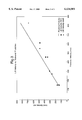
- FIG. 3 is a plot showing the correlation between the calculated velocity and the subsonic prediction.
- a high power laser 10 such as a Q-switched Neodymium/YAG laser
- a lens 12 is focused by a lens 12 in a small volume of gas.
- the gas around the focus is ionised and a laser induced (dielectric) breakdown spark 15 is generated in the gas volume.
- a Q-switched Neodymium/YAG laser 10 which has a pulse energy of approximately 300 mJ in 10 ns long pulses.
- the pulse of laser energy emitted by the laser 10 is focused by a 127 mm focal length lens 12 to generate the laser induced breakdown spark 15 in the gas volume.
- the Q-switched Neodymium/YAG laser 10 produces the laser induced breakdown spark 15 in an air jet 14 emerging from a 37 mm diameter nozzle 16 at ambient temperature.
- the arrangement described could be used to produce laser induced breakdown sparks in other media liquid or gaseous. Indeed the arrangement described has been used to generate laser induced breakdown sparks in an atmospheric pressure propane flame.
- the delayed image which is due to the persistent light emitting species is shifted in the direction of the flow relative to the initial synchronous image.
- the shift in the center of the images was measured to enable the velocity of the fluid flow to be calculated.
- FIG. 2 shows examples of the images recorded, the laser beam direction is from top to bottom.
- the intensifier is not sensitive to 1064 nm light, hence only the visible emissions and not the scattered light from the initial spark are recorded. Light emitting species can be seen diffusing from the position of the original spark up to 9.5 ⁇ s after the laser pulse.
- FIG. 3 shows the velocities estimated from laser induced breakdown images plotted against values estimated from the air mass flow using equation (1);
- A is the nozzle area
- p is the air density outside the nozzle.
- This velocimetry technique offers the advantages that it is non-intrusive, requires no particle or molecular seeding and is particularly suited to high speed flows.
- Temperature measurements can be obtained for a static flow by comparing the rate of increase of the light emitted from the delayed image to the synchronous image of the laser induced breakdown spark.
- Laser induced breakdown is a simple non-intrusive technique which has been demonstrated for velocimetry and temperature measurement.
- the technique also has the potential for simultaneous species concentration and pressure measurement.
Landscapes
- Physics & Mathematics (AREA)
- General Physics & Mathematics (AREA)
- Engineering & Computer Science (AREA)
- Aviation & Aerospace Engineering (AREA)
- Health & Medical Sciences (AREA)
- Analytical Chemistry (AREA)
- Life Sciences & Earth Sciences (AREA)
- Chemical & Material Sciences (AREA)
- Nuclear Medicine, Radiotherapy & Molecular Imaging (AREA)
- Biochemistry (AREA)
- General Health & Medical Sciences (AREA)
- Plasma & Fusion (AREA)
- Immunology (AREA)
- Pathology (AREA)
- Optics & Photonics (AREA)
- Investigating, Analyzing Materials By Fluorescence Or Luminescence (AREA)
- Measuring Volume Flow (AREA)
- Indicating Or Recording The Presence, Absence, Or Direction Of Movement (AREA)
Abstract
Description
Velocity=u=(dM/dt)/pA (1)
Claims (18)
Applications Claiming Priority (2)
| Application Number | Priority Date | Filing Date | Title |
|---|---|---|---|
| GB9807220 | 1998-04-04 | ||
| GBGB9807220.0A GB9807220D0 (en) | 1998-04-04 | 1998-04-04 | Fluid diagnostic technique |
Publications (1)
| Publication Number | Publication Date |
|---|---|
| US6134001A true US6134001A (en) | 2000-10-17 |
Family
ID=10829839
Family Applications (1)
| Application Number | Title | Priority Date | Filing Date |
|---|---|---|---|
| US09/280,977 Expired - Lifetime US6134001A (en) | 1998-04-04 | 1999-03-30 | Fluid diagnostic technique |
Country Status (4)
| Country | Link |
|---|---|
| US (1) | US6134001A (en) |
| EP (1) | EP0947826B1 (en) |
| DE (1) | DE69941317D1 (en) |
| GB (1) | GB9807220D0 (en) |
Cited By (4)
| Publication number | Priority date | Publication date | Assignee | Title |
|---|---|---|---|---|
| US6433877B2 (en) * | 1998-04-03 | 2002-08-13 | Advantest Corporation | Surface inspection using the ratio of intensities of s- and p-polarized light components of a laser beam reflected a rough surface |
| US20060146910A1 (en) * | 2004-11-23 | 2006-07-06 | Manoochehr Koochesfahani | Method and apparatus for simultaneous velocity and temperature measurements in fluid flow |
| US20070107512A1 (en) * | 2005-03-23 | 2007-05-17 | Ohm Electric Co., Ltd. | Flow state observation device and flow state observation method |
| US10598682B2 (en) | 2016-02-12 | 2020-03-24 | Board Of Trustees Of Michigan State University | Laser system for measuring fluid dynamics |
Families Citing this family (5)
| Publication number | Priority date | Publication date | Assignee | Title |
|---|---|---|---|---|
| DE19957808C2 (en) * | 1999-12-01 | 2002-10-10 | Fraunhofer Ges Forschung | Method for determining substance concentrations and / or the flow rate in a gas, aerosol or dust and devices for carrying out the method |
| DE102010019811A1 (en) * | 2010-05-06 | 2011-11-10 | Airbus Operations Gmbh | Method and device for measuring the flow velocity by means of a plasma |
| DE102010030143A1 (en) * | 2010-06-16 | 2011-12-22 | Deutsches Zentrum für Luft- und Raumfahrt e.V. | Method for determining local flow rates of e.g. air, involves spatially and temporarily limiting energy of external fluid in flowing fluid or refractive index of flowing fluid to generate density fluctuation in flowing fluid |
| CN109211879B (en) * | 2018-08-31 | 2022-02-15 | 南京朔宁光电科技有限公司 | Gas remote measuring device and method |
| CN114688990B (en) * | 2020-12-28 | 2023-11-03 | 北京振兴计量测试研究所 | A multi-parameter three-dimensional measurement device, system and method based on light field camera |
Citations (2)
| Publication number | Priority date | Publication date | Assignee | Title |
|---|---|---|---|---|
| US5153665A (en) * | 1991-06-14 | 1992-10-06 | The United States Of America As Represented By The Administrator Of The National Aeronautics And Space Administration | Vaporizing particle velocimeter |
| US5333044A (en) * | 1992-11-24 | 1994-07-26 | The United States Of America As Represented By The Department Of Energy | Fluorescent image tracking velocimeter |
Family Cites Families (2)
| Publication number | Priority date | Publication date | Assignee | Title |
|---|---|---|---|---|
| US4925307A (en) * | 1984-05-01 | 1990-05-15 | The United States Of America As Represented By The United States Department Of Energy | Apparatus and method for the spectrochemical analysis of liquids using the laser spark |
| US5002389A (en) * | 1988-12-22 | 1991-03-26 | Honeywell Inc. | Pulsed fluorescence velocimeter |
-
1998
- 1998-04-04 GB GBGB9807220.0A patent/GB9807220D0/en not_active Ceased
-
1999
- 1999-03-29 DE DE69941317T patent/DE69941317D1/en not_active Expired - Lifetime
- 1999-03-29 EP EP99302451A patent/EP0947826B1/en not_active Expired - Lifetime
- 1999-03-30 US US09/280,977 patent/US6134001A/en not_active Expired - Lifetime
Patent Citations (2)
| Publication number | Priority date | Publication date | Assignee | Title |
|---|---|---|---|---|
| US5153665A (en) * | 1991-06-14 | 1992-10-06 | The United States Of America As Represented By The Administrator Of The National Aeronautics And Space Administration | Vaporizing particle velocimeter |
| US5333044A (en) * | 1992-11-24 | 1994-07-26 | The United States Of America As Represented By The Department Of Energy | Fluorescent image tracking velocimeter |
Non-Patent Citations (4)
| Title |
|---|
| On the cooling of the plasma fireball produced by a laser spark in front of liquids and solids D.Kaganovich et al., Phys. Plasmas 3 (2), Feb. 1996; 1996 American Institute of Physics. * |
| On the cooling of the plasma fireball produced by a laser spark in front of liquids and solids--D.Kaganovich et al., Phys. Plasmas 3 (2), Feb. 1996; 1996 American Institute of Physics. |
| Spectroscopic study of laser produced plasmas in hydrogen, J. F. Kielkopf, vol. 52, No. 2, Physical Review E. Aug. 1995. * |
| Spectroscopic study of laser-produced plasmas in hydrogen, J. F. Kielkopf, vol. 52, No. 2, Physical-Review E. Aug. 1995. |
Cited By (4)
| Publication number | Priority date | Publication date | Assignee | Title |
|---|---|---|---|---|
| US6433877B2 (en) * | 1998-04-03 | 2002-08-13 | Advantest Corporation | Surface inspection using the ratio of intensities of s- and p-polarized light components of a laser beam reflected a rough surface |
| US20060146910A1 (en) * | 2004-11-23 | 2006-07-06 | Manoochehr Koochesfahani | Method and apparatus for simultaneous velocity and temperature measurements in fluid flow |
| US20070107512A1 (en) * | 2005-03-23 | 2007-05-17 | Ohm Electric Co., Ltd. | Flow state observation device and flow state observation method |
| US10598682B2 (en) | 2016-02-12 | 2020-03-24 | Board Of Trustees Of Michigan State University | Laser system for measuring fluid dynamics |
Also Published As
| Publication number | Publication date |
|---|---|
| EP0947826A2 (en) | 1999-10-06 |
| EP0947826A3 (en) | 1999-11-03 |
| GB9807220D0 (en) | 1998-06-03 |
| EP0947826B1 (en) | 2009-08-26 |
| DE69941317D1 (en) | 2009-10-08 |
Similar Documents
| Publication | Publication Date | Title |
|---|---|---|
| Danehy et al. | Flow-tagging velocimetry for hypersonic flows using fluorescence of nitric oxide | |
| Rusak et al. | Recent trends and the future of laser-induced plasma spectroscopy | |
| US6134001A (en) | Fluid diagnostic technique | |
| Ben-Yakar et al. | Ultra-fast-framing schlieren system for studies of the time evolution of jets in supersonic crossflows | |
| US20140071256A1 (en) | Femtosecond laser excitation tagging anemometry | |
| Song et al. | Mechanisms of absorption in pulsed excimer laser-induced plasma. | |
| Barker et al. | Supersonic velocimetry in a shock tube using laser enhanced ionisation and planar laser induced fluorescence | |
| Rubinsztein-Dunlop et al. | Ionic strontium fluorescence as a method for flow tagging velocimetry | |
| McIntyre et al. | Optical and pressure measurements in shock tunnel testing of a model scramjet combustor | |
| Bianchini et al. | Real-space laser-induced fluorescence imaging applied to gas-liquid interfacial scattering | |
| US20070019182A1 (en) | Arc/spark optical emission spectroscopy correlated with spark location | |
| Larigaldie et al. | Velocity measurement in hypersonic flows using electron-beam-assisted glow discharge | |
| Gregory et al. | Characterization of Hartmann tube flow with porous pressure-sensitive paint | |
| Heitmann et al. | Non-intrusive generation of instability waves in a planar hypersonic boundary layer | |
| Grib et al. | Velocimetry measurements in a Mach 6 Ludwieg tube | |
| Zhang et al. | Shear layer measurements along curved surfaces using the FLEET method | |
| Getsinger | Shear layer instabilities and mixing in variable density transverse jet flows | |
| Kolesnichenko et al. | Microwave discharge parameters in supersonic flow | |
| Gray | A shock tube with tunable, pulsed laser‐based diagnostics | |
| White et al. | Shock propagation through a low-pressure glow discharge in argon | |
| Jiang et al. | High-speed Laser Diagnostics in Hypersonic Flows | |
| Lester et al. | Velocity, mach number, and static temperature measurements in supersonic flows with 10 kHz laser-induced schliere anemometry | |
| WO1996031900A1 (en) | A method and device for the analysis of the chemical composition of particles | |
| Marshall et al. | Developing Multi-line FLEET using Periodic Mask Design. | |
| Alessandretti et al. | Flame propagation monitoring in an engine by an optical technique |
Legal Events
| Date | Code | Title | Description |
|---|---|---|---|
| AS | Assignment |
Owner name: ROLLS-ROYCE PLC, ENGLAND Free format text: ASSIGNMENT OF ASSIGNORS INTEREST;ASSIGNOR:BLACK, JOHN DAVID;REEL/FRAME:009993/0322 Effective date: 19990428 |
|
| STCF | Information on status: patent grant |
Free format text: PATENTED CASE |
|
| FEPP | Fee payment procedure |
Free format text: PAYER NUMBER DE-ASSIGNED (ORIGINAL EVENT CODE: RMPN); ENTITY STATUS OF PATENT OWNER: LARGE ENTITY Free format text: PAYOR NUMBER ASSIGNED (ORIGINAL EVENT CODE: ASPN); ENTITY STATUS OF PATENT OWNER: LARGE ENTITY |
|
| FPAY | Fee payment |
Year of fee payment: 4 |
|
| FPAY | Fee payment |
Year of fee payment: 8 |
|
| FEPP | Fee payment procedure |
Free format text: PAYOR NUMBER ASSIGNED (ORIGINAL EVENT CODE: ASPN); ENTITY STATUS OF PATENT OWNER: LARGE ENTITY |
|
| FPAY | Fee payment |
Year of fee payment: 12 |