US613142A - Air-brake - Google Patents
Air-brake Download PDFInfo
- Publication number
- US613142A US613142A US613142DA US613142A US 613142 A US613142 A US 613142A US 613142D A US613142D A US 613142DA US 613142 A US613142 A US 613142A
- Authority
- US
- United States
- Prior art keywords
- air
- valve
- piston
- reservoir
- auxiliary
- Prior art date
- Legal status (The legal status is an assumption and is not a legal conclusion. Google has not performed a legal analysis and makes no representation as to the accuracy of the status listed.)
- Expired - Lifetime
Links
- 241001474033 Acar Species 0.000 description 1
- 238000010276 construction Methods 0.000 description 1
Images
Classifications
-
- B—PERFORMING OPERATIONS; TRANSPORTING
- B60—VEHICLES IN GENERAL
- B60T—VEHICLE BRAKE CONTROL SYSTEMS OR PARTS THEREOF; BRAKE CONTROL SYSTEMS OR PARTS THEREOF, IN GENERAL; ARRANGEMENT OF BRAKING ELEMENTS ON VEHICLES IN GENERAL; PORTABLE DEVICES FOR PREVENTING UNWANTED MOVEMENT OF VEHICLES; VEHICLE MODIFICATIONS TO FACILITATE COOLING OF BRAKES
- B60T15/00—Construction arrangement, or operation of valves incorporated in power brake systems and not covered by groups B60T11/00 or B60T13/00
- B60T15/02—Application and release valves
- B60T15/18—Triple or other relay valves which allow step-wise application or release and which are actuated by brake-pipe pressure variation to connect brake cylinders or equivalent to compressed air or vacuum source or atmosphere
- B60T15/24—Triple or other relay valves which allow step-wise application or release and which are actuated by brake-pipe pressure variation to connect brake cylinders or equivalent to compressed air or vacuum source or atmosphere controlled by three fluid pressures
- B60T15/30—Triple or other relay valves which allow step-wise application or release and which are actuated by brake-pipe pressure variation to connect brake cylinders or equivalent to compressed air or vacuum source or atmosphere controlled by three fluid pressures with a quick braking action
- B60T15/302—Railway control or brake valves with evacuation of air to a reservoir, to the atmosphere or to the brake cylinder
- B60T15/304—Railway control or brake valves with evacuation of air to a reservoir, to the atmosphere or to the brake cylinder with one slide valve
Definitions
- the invention is an improvement in the main piston of a triple valve of an automatic air-brake system for the purpose of passing air from a train-pipe to the auxiliary air-reservoir (located on acar) in the position of brakes applied for the purpose of replenishing the auxiliary air-reservoir without a release of the air from the air-brake cylinder.
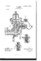
- Figure 1 is a longitudinal section through the ordinary triple valve of an automatic airbrake, showing the double-seating valve in the main piston 9, which constitutes my invention.
- Fig. 2 is a sectional detail, on a larger scale, of the double-seating valve; and Fig. 3 is a similar view showing another position of said valve.
- the numeral 1 indicates a part of the brake-cylinder. 2 is its head, which is cored out to form a passage-way 3, through which compressed air is admitted to the cylinder in applying the brakes, and with which head, ate, the air-pipe from the auxiliary air-reservoir (not shown) is connected.
- the numerals 5 to 27 represent the various parts of the triple valve of the Westinghouse system. These parts I need not describe in detail, as they are all old and in common use; but it will be essential for the purpose of clearly distinguishing my invention and accentuating its importance to describe the general operation of this triple valve and its de fects, and for this purpose I will describe the action that takes place in applying and releasing the brakes by the old devices.
- the brakes are applied as follows
- the engineer reduces pressure in the trainpipe. Up to this time the pressure of the auxiliary air-reservoir is on one side of pis ton 9 and the pressure in the train-pipe through chambers 6 and 7 is on the other side, and an equal pressure on both sides is maintained through the passage-way 23 around the said piston; but when the engineer reduces pressure in the train-pipe, and consequently in chambers 6 and 7, the piston 9 moves over to the right and strikes against the spring-seated stem 8.
- My invention provides means for recharging the auxiliary air-reservoir while the brakes are still applied or before the air is discharged .from the brake-cylinder, so that the auxiliary air-reservoir is ready to do its full and effective work atits normal pressure in a second application of brakes immediately after the brakes are taken off.
- This valve consists of two heads a, and (1 closing alternately overa port a on the brake side of the pistoma stem A,rigidly connecting the heads, a spiral spring a surrounding the inner end of the stem and located between the head a and the inner closed end of the hub, and a head a fixed on the outer end of the stem, closing an opening a in a detachable cap A, and having radial arms or cut-away periphery to guide the stem and still allow air to pass when it leaves its seat over the opening a.
- the head a closely fits the bore of the chamber all around, while a closely fits it over the port 0. but has a cut-away periphcry or port a on its upper edge to let air pass.
- the valve is made removable, as shown in Figs. 2 and 3, by screw-cap A, as is also the spring coiled around its stem at its inner end, said spring holdingthe valve to its seat at a, as shown in Fig. 2, and preventing any flow of air from the train-pipe through port a, and ports a and a when the piston is in its normal position of brakes released or on the extreme left and in the plane of a passage 23, with the pressure equalized on both sides of the main piston.
- the piston as shown, is in the position of brakes applied and the double-seated valve is closed to both train-pipe pressure at a and auxiliary pressure at a, the head a performing the functions of a valve and closing port a.
- This valve has a pulsating action responding to slight increase of pressure on its train-pipe side and closing by its spring-tension when pressures are equalized on both sides of piston 9, the piston 9 being the dividing-line between train-pipe and auxiliary pressure.
- the engineer places his valve in the full-release position, throwing the excess pressure into the train-pipe, the air taking same course as heretofore described and forcing the double-seated valve to the extreme limit of its travel, compressing the spring, as shown in Fig. 3, and valve-head a closing port a allowing no air to pass by the valve to the auxiliary reservoir in the position of brakes released.
- the spring restores the double-seated valve to its normal position, as shown in Fig.
- the piston 9 of the triple valve having within its hub a double-seating valve yielding inwardly from the pressure on the trainpipe side substantially as described.
- the piston 9 of the triple valve having within the same a double-seatin g valve yielding inwardly from the pressure on the trainpipe side, and opening with a partial range of movement to let air pass, and closing with an extreme range of movement to close the air-passage substantially as and for the purpose described.
Landscapes
- Engineering & Computer Science (AREA)
- Physics & Mathematics (AREA)
- Fluid Mechanics (AREA)
- Transportation (AREA)
- Mechanical Engineering (AREA)
- Valves And Accessory Devices For Braking Systems (AREA)
Description
Patented Oct. 25, I898. w. T. HAMAB. AIR BRAKE.
(Application filed Apr. 22, 1897.)
(No Model.)
INVENTOR.
WITNESSES t l W ATTORNEYS NITED STATES PATENT OFFICE.
WILLI M T. HAMAR, OF ATLANTA, GEORGIA.
AIR-BRAKE.
SPECIFICATION forming part of Letters Patent No. 613,142, dated. October 25, 1898. Application filed April 22, 1897. Serial No. 633,337. (No model.)
To ctZZ whom, it may concern.-
Be it known that I, WILLIAM T. HAMAR, of Atlanta,in the county of Fulton and State of Georgia, have invented a new and useful Improvement in Air-Brakes, of which the following is a specification.
The invention is an improvement in the main piston of a triple valve of an automatic air-brake system for the purpose of passing air from a train-pipe to the auxiliary air-reservoir (located on acar) in the position of brakes applied for the purpose of replenishing the auxiliary air-reservoir without a release of the air from the air-brake cylinder.
Figure 1 is a longitudinal section through the ordinary triple valve of an automatic airbrake, showing the double-seating valve in the main piston 9, which constitutes my invention. Fig. 2 is a sectional detail, on a larger scale, of the double-seating valve; and Fig. 3 is a similar view showing another position of said valve.
Referring to Fig. 1, the numeral 1 indicates a part of the brake-cylinder. 2 is its head, which is cored out to form a passage-way 3, through which compressed air is admitted to the cylinder in applying the brakes, and with which head, ate, the air-pipe from the auxiliary air-reservoir (not shown) is connected.
5 is the connection for the train-pipe, and
, the numerals 5 to 27 represent the various parts of the triple valve of the Westinghouse system. These parts I need not describe in detail, as they are all old and in common use; but it will be essential for the purpose of clearly distinguishing my invention and accentuating its importance to describe the general operation of this triple valve and its de fects, and for this purpose I will describe the action that takes place in applying and releasing the brakes by the old devices.
Assuming that the triple-valve piston 9 is to the extreme left of Fig. 1, which is the normal position of brakes released with the old system, the brakes are applied as follows The engineer reduces pressure in the trainpipe. Up to this time the pressure of the auxiliary air-reservoir is on one side of pis ton 9 and the pressure in the train-pipe through chambers 6 and 7 is on the other side, and an equal pressure on both sides is maintained through the passage-way 23 around the said piston; but when the engineer reduces pressure in the train-pipe, and consequently in chambers 6 and 7, the piston 9 moves over to the right and strikes against the spring-seated stem 8. As the piston 9 thus moves its stem 11 moves with it and (through a loose drag connection) the graduating-valve 10 is moved to the right to uncover a port 27. This port is in open communication with the space about the piston-stem and the auxiliary air-reservoir, and as valve 10 uncovers the port 27 air from the auxiliary air-reservoir passes through ports 14 and 16 to 3 and the air-brake cylinder. The brakes are now applied and piston 9 moves slightly back from spring-stem 8 to the position shown in Fig. 1 and the graduating-valve 10 closes port 27, as shown in Fig. 1. Now to discharge the brake-cylinder and recharge the auxiliary air-reservoir the engineer throws a heavier pressure on the train-pipe than that carried normally by the auxiliary reservoir, and this forces the piston 9 against the auxiliary-air-reservoir pressure to the extreme left. This causes the passage-way 26 of the slide-valve 13 to cover the ports 16 and 25, and as 16 is in communication with the airbrake cylinder and 25 is the exhaustport opening into the air it will be seen that the air from the air-brake cylinder is discharged into the outer air and the brakes released. Immediately'following this the depleted pressure in the auxiliary air-reservoir is restored to normal from the train-pipe byaflow of air through chambers 6 7 around the piston 9 through passage-way 23, thence to the space around the slide-valve 13 and to the cored passage-way 4, leading to auxiliary air-reservoir. It will thus be seen that with this construction the air in the auxiliary reservoir can only be replenished after the air-brake cylinder is discharged and the brakes released.
My invention provides means for recharging the auxiliary air-reservoir while the brakes are still applied or before the air is discharged .from the brake-cylinder, so that the auxiliary air-reservoir is ready to do its full and effective work atits normal pressure in a second application of brakes immediately after the brakes are taken off.
My improvement consists of a double=seated valve, Figs. 2 and 3, located in the hub of the main piston 9, as shown in Fig. 1. This valve consists of two heads a, and (1 closing alternately overa port a on the brake side of the pistoma stem A,rigidly connecting the heads, a spiral spring a surrounding the inner end of the stem and located between the head a and the inner closed end of the hub, and a head a fixed on the outer end of the stem, closing an opening a in a detachable cap A, and having radial arms or cut-away periphery to guide the stem and still allow air to pass when it leaves its seat over the opening a. The head a closely fits the bore of the chamber all around, while a closely fits it over the port 0. but has a cut-away periphcry or port a on its upper edge to let air pass.
The valve is made removable, as shown in Figs. 2 and 3, by screw-cap A, as is also the spring coiled around its stem at its inner end, said spring holdingthe valve to its seat at a, as shown in Fig. 2, and preventing any flow of air from the train-pipe through port a, and ports a and a when the piston is in its normal position of brakes released or on the extreme left and in the plane of a passage 23, with the pressure equalized on both sides of the main piston. Referring to Fig. 1, the piston, as shown, is in the position of brakes applied and the double-seated valve is closed to both train-pipe pressure at a and auxiliary pressure at a, the head a performing the functions of a valve and closing port a. The engineer now, desiring to recharge his auxiliary air-reservoir, places his valve on the engine in a position to admit air to the train-pipe,which enters the triple valve at the train-pipe connection 5, passing through ports 6 and 7 into main piston-chamber, forcing valve-heads a a and a from the position shown in Fig. 2 with a partial range of movement which leaves the port on between the heads a and a thereby establishing communication from train-pipe to auxiliary air-reservoir through ports a, a, and a, and thence through slide-valve chamber 11 and inletpipe 4, leading to auxiliary air-reservoir. The pressure becoming equalized, spring a restores valve to its seat, as shown in Figs. 1 and 2. This valve has a pulsating action responding to slight increase of pressure on its train-pipe side and closing by its spring-tension when pressures are equalized on both sides of piston 9, the piston 9 being the dividing-line between train-pipe and auxiliary pressure. Now in making a final and full release of the brakes the engineer places his valve in the full-release position, throwing the excess pressure into the train-pipe, the air taking same course as heretofore described and forcing the double-seated valve to the extreme limit of its travel, compressing the spring, as shown in Fig. 3, and valve-head a closing port a allowing no air to pass by the valve to the auxiliary reservoir in the position of brakes released. The spring then restores the double-seated valve to its normal position, as shown in Fig. 2, in which it is closed to both train-pipe and auxiliary reservoir. It may be well to state, however, that in the position of brakes released the piston 9 is moved inwardly, opening passage-way 23 on opposite sides of the piston 9 and allowing air to flow past piston 9 to auxiliary reservoir in the manner described and as provided for by the Westinghouse system, that feature forming no part of my invention. It will be readily observed that the device mentioned opens with a partial range of movement in recharging and closes with an extreme range of movement in releasing.
Having thus described my invention,what I claim as new, and desire to secure by Letters Patent, is-
1. The piston 9 of the triple valve having within its hub a double-seating valve yielding inwardly from the pressure on the trainpipe side substantially as described.
2. The piston 9 of the triple valve having within the same a double-seatin g valve yielding inwardly from the pressure on the trainpipe side, and opening with a partial range of movement to let air pass, and closing with an extreme range of movement to close the air-passage substantially as and for the purpose described.
WILLIAM T. HAMAR. Witnesses:
EDW. W. BYRN, SoLoN O. KEMoN.
Publications (1)
| Publication Number | Publication Date |
|---|---|
| US613142A true US613142A (en) | 1898-10-25 |
Family
ID=2681753
Family Applications (1)
| Application Number | Title | Priority Date | Filing Date |
|---|---|---|---|
| US613142D Expired - Lifetime US613142A (en) | Air-brake |
Country Status (1)
| Country | Link |
|---|---|
| US (1) | US613142A (en) |
-
0
- US US613142D patent/US613142A/en not_active Expired - Lifetime
Similar Documents
| Publication | Publication Date | Title |
|---|---|---|
| US613142A (en) | Air-brake | |
| US621779A (en) | Signors of one-fourth to charles g | |
| US836886A (en) | Quick-recharging triple valve. | |
| US608095A (en) | charles l | |
| US481136A (en) | Valve for automatic air-brakes | |
| US431304A (en) | Releasing attachment for air-brakes | |
| US478846A (en) | Penter | |
| US918179A (en) | Automatic retaining-valve. | |
| US660650A (en) | Air-brake. | |
| US723769A (en) | Check-valve and brake system. | |
| US715088A (en) | Quick-action automatic release mechanism for air-brakes. | |
| US583278A (en) | Iniventqri | |
| US583279A (en) | George a | |
| US654987A (en) | Retaining-valve. | |
| US749263A (en) | Automatic fluid pressure brake mechanism | |
| US813090A (en) | Air-brake mechanism. | |
| US594464A (en) | Air brake | |
| US634960A (en) | Valve mechanism for air-brakes. | |
| US563673A (en) | Automatic fluid-pressure brake | |
| US458101A (en) | Fluid-pressure brake | |
| US634724A (en) | Air-brake. | |
| US801775A (en) | Triple valve. | |
| US775062A (en) | Air-brake. | |
| US711406A (en) | Fluid-pressure brake. | |
| US431790A (en) | Automatic air-brake |