US6130670A - Method and apparatus for providing simple generalized conservative visibility - Google Patents
Method and apparatus for providing simple generalized conservative visibility Download PDFInfo
- Publication number
- US6130670A US6130670A US08/902,433 US90243397A US6130670A US 6130670 A US6130670 A US 6130670A US 90243397 A US90243397 A US 90243397A US 6130670 A US6130670 A US 6130670A
- Authority
- US
- United States
- Prior art keywords
- occluder
- scene
- node
- camera
- bounding
- Prior art date
- Legal status (The legal status is an assumption and is not a legal conclusion. Google has not performed a legal analysis and makes no representation as to the accuracy of the status listed.)
- Expired - Lifetime
Links
- 238000000034 method Methods 0.000 title claims abstract description 62
- 238000009877 rendering Methods 0.000 claims abstract description 67
- 238000013507 mapping Methods 0.000 claims description 12
- 238000012360 testing method Methods 0.000 claims description 9
- 230000008901 benefit Effects 0.000 claims description 7
- 230000009466 transformation Effects 0.000 claims description 7
- PXFBZOLANLWPMH-UHFFFAOYSA-N 16-Epiaffinine Natural products C1C(C2=CC=CC=C2N2)=C2C(=O)CC2C(=CC)CN(C)C1C2CO PXFBZOLANLWPMH-UHFFFAOYSA-N 0.000 claims description 6
- 230000008569 process Effects 0.000 claims description 6
- 230000008859 change Effects 0.000 claims description 4
- 230000036961 partial effect Effects 0.000 claims description 4
- 230000001131 transforming effect Effects 0.000 claims description 3
- 230000000007 visual effect Effects 0.000 claims description 3
- 230000004913 activation Effects 0.000 claims description 2
- 230000000694 effects Effects 0.000 claims 2
- 230000002452 interceptive effect Effects 0.000 abstract description 8
- 238000010586 diagram Methods 0.000 description 17
- 230000003068 static effect Effects 0.000 description 8
- 230000001427 coherent effect Effects 0.000 description 4
- 238000007781 pre-processing Methods 0.000 description 4
- 230000006872 improvement Effects 0.000 description 2
- 230000002829 reductive effect Effects 0.000 description 2
- 238000004458 analytical method Methods 0.000 description 1
- 238000013459 approach Methods 0.000 description 1
- 238000004364 calculation method Methods 0.000 description 1
- 238000004891 communication Methods 0.000 description 1
- 238000011156 evaluation Methods 0.000 description 1
- 238000013101 initial test Methods 0.000 description 1
- 230000003993 interaction Effects 0.000 description 1
- 230000000670 limiting effect Effects 0.000 description 1
- 238000012545 processing Methods 0.000 description 1
- 239000013598 vector Substances 0.000 description 1
- 230000035899 viability Effects 0.000 description 1
Images


Classifications
-
- G—PHYSICS
- G06—COMPUTING; CALCULATING OR COUNTING
- G06T—IMAGE DATA PROCESSING OR GENERATION, IN GENERAL
- G06T15/00—3D [Three Dimensional] image rendering
- G06T15/10—Geometric effects
- G06T15/40—Hidden part removal
Definitions
- the invention relates to image rendering. More particularly, the invention relates to a method and apparatus for providing simple generalized conservative visibility.
- VRML 2.0 places few constraints on the scene designers. Consequently, any visibility algorithm must be generalizable. Objects in VRML 2.0 can also be added, removed, and transformed through the use of an external interface (such as Java and JavaScript). This means that no object is truly static.
- An external interface such as Java and JavaScript. This means that no object is truly static.
- a good visibility algorithm for VRML scenes cannot rely on assumptions about static elements in the scene.
- Many current VRML viewers rely on third party rendering engines to perform the low level rendering of the objects, limiting the viability of algorithms that use such techniques as polygon splitting or merging. Consequently, algorithms that increase rendering performance must do the majority of their work before the low level rendering calls are performed.
- Effective conservative visibility algorithms attempt to cull a large number of elements from the scene quickly.
- a visibility algorithm is considered conservative if it overestimates the number of visible elements, generating a conservative set instead of an exact set of visible elements (see S. Coorg, S. Teller, A Spatially and Temporally Coherent Object Space Visibility Algorithm, Tech. Re. TM-546, Laboratory for Computer Science, MIT, (1996); and S. Coorg, S. Teller, Temporally Coherent Conservative Visibility, Twelfth Annual ACM Symposium on Computational Geometry (1996)).
- a typical conservative visibility algorithm identifies a superset of the visible polygons.
- the standard rendering subsystem is left with the task of determining the exact rendering of the scene given the reduced set of visible elements.
- the hardware or software optimizations used by the underlying rendering subsystem such as hardware Z-buffering, are preserved.
- the computational time necessary to perform the conservative visibility algorithms must be less than the time necessary to apply the underlying rendering subsystem to the culled elements. Consequently, conservative visibility algorithms are especially useful when they can generate a reasonably tight upper bound on the number of elements in the scene.
- the invention provides an occluder primitive and a simple associated algorithm that greatly improves the rendering performance of large scenes. Because this algorithm works on both polygons and objects, the term "elements" is used herein to represent either polygons and/or objects.
- the occluder primitive and associated algorithm are simple to implement in three dimensional viewers and highly generalizable. For example, the presently preferred embodiment of the invention is readily implemented in a VRML 2.0 viewer.
- Occluder nodes which are planes with given width and height in object space that block the rendering of objects behind them in world space, are used to compute a conservative set of visible objects from a current viewpoint.
- Occluder nodes can be incorporated by scene designers using authoring tools to perform many high performance rendering techniques, including culling geometry in densely occluded models, region based scene division, and using images to represent far distant geometry.
- generalized scene viewers are provided that allow interactive rendering of complex worlds, including multi-user environments, architectural models, three dimensional games, and large engineering models.
- the invention provides an algorithm based on occluders that allows general three dimensional viewers to support complex worlds better, including multi-user environments, games, architectural walkthroughs, and large engineering models.
- the algorithm does not require an extensive preprocessing step, computationally expensive per frame operations, or excessive memory requirements.
- the algorithm performs all of its work before the underlying rendering engine is called. This supports viewers that use third party rendering engines, or performance enhanced low level rendering engines. Occluders do not require objects in the scene to be static, and the algorithm is sufficiently generalizable to many three dimensional applications.
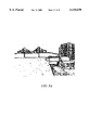
- FIG. 1a is a schematic diagram that illustrates a bounding box that is completely unobstructed by an occluder according to the invention
- FIG. 1b is a schematic diagram that illustrates a bounding box that is partially occluded according to the invention
- FIG. 1c is a schematic diagram that illustrates a bounding box that is completely occluded by an occluder according to the invention
- FIG. 2a is a schematic diagram that illustrates a two dimensional bounding square, and the location of an occluder according to the invention
- FIG. 2b is a schematic diagram that illustrates bounding lines, where a gray area demarks the area in which an object is occluded according to the invention
- FIG. 2c is a schematic diagram that illustrates two occluders in a scene according to the invention.
- FIG. 2d is a schematic diagram that illustrates bounding areas for two different squares according to the invention.
- FIG. 3 is a schematic diagram that illustrate the activationDistance field in the occluder, which specifies how far the camera must be from the occluder for the occluder to be active, according to the invention
- FIG. 4a is a schematic diagram that illustrates a bounding box, and the location of an occluder, shown as a transparent plane according to the invention
- FIG. 4b is a schematic diagram that illustrates a scene that has been transformed into occluder space according to the invention.
- FIG. 4c is a schematic diagram that illustrates bounding planes in world space as calculated to form the occlusion volume according to the invention
- FIG. 5a is a schematic diagram that illustrates an example in which an occluder completely covers an outer accumulated bounding box, such that everything within the bounding box is occluded, according to the invention
- FIG. 5b is a schematic diagram that illustrates an example in which an accumulated bounding box is not fully occluded, such that certain elements within the bounding box are visible, according to the invention
- FIG. 6a is an image that illustrates Quake Start Level, in which the transparent plane highlights the location of an invisible occluder, and in which the occluder is not active and thus the geometry behind the occluder is visible according to the invention;
- FIG. 6b is an image that illustrates an occluder that is active where the geometry behind the occluder is not visible according to the invention
- FIG. 6c is an image that illustrates an image from inside a world is identical whether or not the occluder is visible, and where the occluder shown in FIGS. 6a and 6b is just behind the far wall according to the invention;
- FIG. 7a is an image taken from Virtual Union Square, in which transparent planes show the position of the occluders, where the occluders are spaced such that they form distinct regions according to the invention;
- FIG. 7b is an image in which the original scene presented in FIG. 7a is shown without occluders according to the invention.
- FIG. 7c is an image in which the scene presented in FIG. 7a is rendered with occluders using automatic texture mapping and an activationDistance corresponding to the size of a cell according to the invention
- FIG. 8a is an image in which a rendered scene is shown without an occluder according to the invention.
- FIG. 8b is an image in which an occluder has been added, but automatic mapping of textures is disabled according to the invention.
- FIG. 8c is an image in which a texture is mapped to an occluder, such that an image of the bridge shown in FIG. 8a appear according to the invention
- FIG. 9 is a flow diagram that illustrates the use of occluders as part of an image rendering procedure according to the invention.
- FIG. 10 is a block schematic diagram of an apparatus for providing simple generalized conservative visibility according to the invention.
- the invention provides an occluder primitive and a simple associated algorithm that greatly improves the rendering performance of large scenes. Because this algorithm works on both polygons and objects, the term "elements" is used herein to represent either polygons and/or objects.
- the occluder primitive and associated algorithm are simple to implement in three dimensional viewers and highly generalizable. For example, the presently preferred embodiment of the invention is readily implemented in a VRML 2.0 viewer.
- Occluder nodes which are planes with given width and height in object space that block the rendering of objects behind them in world space, are used to compute a conservative set of visible objects from a current viewpoint.
- Occluder nodes can be incorporated by scene designers and authoring tools to perform many high performance rendering techniques, including culling geometry in densely occluded models, region based scene division, and using images to represent far distant geometry. Using this simple primitive, generalized scene viewers are provided that allow interactive rendering of complex worlds, including multi-user environments, architectural models, three dimensional games, and large engineering models.
- the invention provides an algorithm based on occluders that allows general three dimensional viewers to support complex worlds better, including multi-user environments, games, architectural walkthroughs, and large engineering models.
- the algorithm does not require an extensive preprocessing step, computationally expensive per frame operations, or excessive memory requirements.
- the algorithm performs all of its work before the underlying rendering engine is called. This supports viewers that use third party rendering engines, or performance enhanced low level rendering engines. Occluders do not require objects in the scene to be static, and the algorithm is sufficiently generalizable to many three dimensional applications.
- Objects correspond to VRML 2.0 Shapes, such as Spheres, Cubes, and IndexedFaceSets.
- Occluder nodes can be described as a plane in world space with a given center, width, height, and normal. If an object lies in the positive half space of the occluder node, and the entire object bounding box lies within the area of the occluder in eye space, then the object is considered occluded.
- An object is not visible from the camera position if and only if all the vertices of its bounding box are occluded by a single occluder node in camera space.
- Each object's bounding box can exist in three states relative to an occluder.
- the bounding box 12 can be completely unobstructed by the occluder 12 (FIG. 1a), in which case the object is visible.
- Changing the viewpoint can cause the bounding box 10 to be partially occluded by the occluder 12 (FIG. 1b).
- the preferred embodiment of the invention does not use information about partial occlusion, although algorithms that take advantage of partial occlusion have been developed (see S. Coorg, S. Teller, A Spatially and Temporally Coherent Object Space Visibility Algorithm, Tech. Re. TM-546, Laboratory for Computer Science, MIT, (1996); and S. Coorg, S.
- an occluder node in object space is a plane centered at coordinate 0,0,0 with a given width and height.
- An occluder's normal is in the positive-Z direction in VRML's right handed coordinate system.
- the following VRML 2.0 prototype describes the fields in an occluder node:
- the occluder has a Boolean field which controls whether or not the occluder is active in the scene.
- the Boolean field can be exposed to an external interface to control which occluders are active. By default the occluder is active. Inactive occluders have no affect on the scene.
- the height and width fields specify the dimensions of the occluder plane and are set at 1.0 unit by default.
- the activationDistance field specifies how far the camera must be from the occluder for the occluder to be active. This means that when the camera gets close enough to the occluder, the geometry behind the occluder becomes visible. By default, the activation distance is set at 0.0 units, meaning the occluder is always active.
- the VRML prototype for an occluder is:
- affine transformation can be applied to an occluder. Consequently, occluders can be transformed to any position in world space.
- occluders can be transformed to any position in world space.
- an affine transformation is a transformation of the form:
- An affine transformation maps parallel lines into parallel lines, finite points into finite points, leaves the line at infinity fixed, and preserves the ratio of the distance separating three points that line on a straight line.
- Simple occluder nodes have no visible geometry. They can, however, be placed coplanar with other geometry. For instance, a designer can place an occluder coplanar with a wall. This allows designers to add occluder nodes to scenes after the scene has been completely designed without changing the visual appearance of the scene.
- Occluders also have global scope relative to the scene. Any object at any distance from the occluder is deemed not visible if its bounding box is completely contained within the occluder relative to the camera. Because an occluder is one sided, only objects in the negative half space of the occluder can ever be occluded.
- FIG. 2 presents the two dimensional case.
- the occluder 10 is represented as a one dimensional line, and the object 20 as a two dimensional bounding square (FIG. 2a).
- the bounding lines between the occluder and the object are calculated.
- the intersection of the area on the opposite side of the occluder from the object and the area in between the bounding lines represents the area in which the object is fully occluded (FIG. 2b). If the camera is in this region, the object is not visible to the camera and should not be rendered.
- This simple algorithm can be extended to multiple occluders 10a, 10b (FIG.
- Region A is the intersection of these two areas and denotes the region in which both objects are occluded.
- the activationDistance field in the Occluder specifies how far the camera must be from the occluder for the occluder to be active.
- the two dimensional case for this is shown in FIG. 3.
- the object 20 represented by the bounding square is marked as not visible.
- the occluder becomes inactive and the object is marked visible.
- the bounding planes form the bounding volume in which the object is occluded, which is referred to herein as the occlusion volume.
- the occlusion volume is the bounding volume in which the object is occluded.
- Calculating the bounding volume requires transforming all objects from world space coordinates (FIG. 4a) into the coordinate space relative to the occluder.
- occluder space coordinates the minimum and maximum x and y vertices of the bounding box 10 are located (FIG. 4b). Then, the vertex corresponding to the maximum y value in occluder space and the top edge of the occluder 12 form a plane in world space coordinates.
- the minimum x vertex and the left edge create the left bounding plane.
- the minimum y vertex and the bottom edge create the bottom bounding plane.
- the maximum x vertex and the right edge create the left bounding plane.
- These four planes combined with the occluder itself comprise the bounding walls of the occlusion volume.
- An occlusion volume can be either a pyramid in the case where the bounding planes intersect in the positive half space of the occluder, or an infinite prism if the bounding planes do not intersect.
- the center of the occluder (FIG. 4b) is location 0,0,0.
- the circled vertices represent the extrema of the bounding cube in occluder space. Using these extrema, the bounding planes in world space are calculated to form the occlusion volume shown in FIG. 4c.
- the occlusion volume extends to infinity along the direction of the occluder normal.
- FIG. 4c illustrates an occlusion volume with bounding planes that do not intersect.
- the normals representing the occlusion volume must be stored with the object. This is accomplished by associating a linked list of bounding volume normals with each shape node in the scene graph. To locate occluders quickly, a linked list is created of pointers to occluder nodes in the scene graph. In the event that an object moves, its occlusion volumes must be recalculated. This is not a compute intensive task.
- the algorithm determines whether or not an object is visible, it is only necessary to traverse the scene graph and find each object containing a set of occlusion volumes. Then, the algorithm loops through each of the occlusion volumes. If the camera is inside one of the occlusion volumes (if the camera position is in the positive half space of the occluder, top, left, bottom, and right planes), then the object is not visible and the visibility is set to false, and the algorithm returns to a starting position.
- the algorithm herein first computes each occlusion volume, i.e. the volume in which the camera cannot see the object because it is blocked by an occluder, as a onetime initialization process at run time. For each frame, the algorithm loops over all of these volumes. If the camera is inside an occlusion volume, then the object associated with that occlusion volume is not visible.
- the performance of the algorithm herein described can be optimized by the designer of the world by altering the number of occluder nodes in a scene. For each frame rendered, the algorithm must analyze each object. For each object, the algorithm must analyze each occluder in the scene. Thus, for each frame rendered, if:
- the algorithm must perform five dot products per O(pn) calculations.
- the algorithm performs fewer than five dot products on average.
- the algorithm described above provides exceptional performance and is an excellent solution for conservative visibility in general three dimensional viewers.
- enhancements to this algorithm are described that further improve speed and provide more options to scene designers. These extensions are not as easily generalizable to any three dimensional viewer.
- the first extension described involves automatically generating and mapping a texture of the scene behind the occluder onto the face of the occluder.
- the second extension involves using hierarchical bounding boxes in the scene to take advantage of the spacial locality of objects to quickly determine their visibility.
- Hierarchical rendering techniques that use texture maps to represent far distant geometry instead of rendering them have been used for interactive rendering of large open spaces (see R. W. Xiong, A Stratified Rendering Algorithm for Virtual Walkthroughs of Large Environments, M.S. Thesis, Massachusetts Institute of Technology, (1996)).
- FIG. 5a shows a set of bounding boxes 51-55 enclosed in a parent bounding box 50.
- the gray area represents an occluder 12. It can be seen that if the occluder fully covers the outer bounding box, all of the progeny are marked as not visible and no further processing is performed.
- FIG. 5b shows the same set of bounding boxes, but the camera position has moved such that the occluder does not fully cover the outer bounding box 50. Because the algorithm then extends to the progeny, it can be seen that the progeny that are still correctly marked are not visible. The algorithm thus checks the progeny and properly determines which of those that are not visible and which are visible.
- This technique is especially effective in a scene in which an entire room is contained in one sub-graph of the scene graph. If that room is occluded by an occluder in the scene, all of the objects in the room are also occluded.
- occluders place occluders in the same position as objects that already block much of the scene. For instance, occluders could be placed along the walls of a room so that the geometry behind the walls is not rendered.
- FIG. 6 shows this technique being used to render a VRML version of the first level of the Quake program.
- the occluder is highlighted as a transparent plane to give a sense of where the occluder is and how it culls the scene.
- the occluder itself is not visible. Because occluders are added by the designer, the occluder can be placed coplanar with a set of adjacent polygons. This is unique because it allows the designer to use co-occlusion with the same simple occluder algorithm.
- FIG. 6 shows Quake Start Level (textures and scene data copyright IdSoftware, modified and screen captured with permission).
- the transparent plane highlights the location of the invisible occluder (FIG. 6a).
- the occluder is not active and thus the geometry behind the occluder is visible.
- the occluder is now active and the geometry behind the occluder is no longer visible.
- FIG. 6c the image from inside the world is identical whether or not the occluder is visible.
- the occluder shown in FIGS. 6a and 6b is just behind the far wall. There are also occluders along the interior walls on the left and right, and below the floor.
- one way to use the invention is to place occluders between each room in a multi-user environment.
- the designer can then set the activationDistance such that the room, and each adjacent room is visible, but all other rooms are not visible because the occluders are far enough away that they are actively occluding the farther rooms.
- the relative occluder distances change and again the adjacent rooms are visible, and the rooms farther away are not. If each room is designed to be part of one hierarchical bounding box, culling can be performed quickly.
- FIG. 7 The image in FIG. 7 is taken from Virtual Union Square (copyright Planet 9 Studies, modified and screen captured by permission).
- FIG. 7a the transparent planes show the position of the occluders. The occluders are spaced such that they form distinct regions.
- FIG. 7b the original scene is shown without occluders.
- FIG. 7c the scene has now been rendered with occluders using automatic texture mapping and an activationDistance corresponding to the size of a cell.
- the only perceptible difference is a slight shift in one building in the background, which is now an image, not true geometry as in FIG. 7b. This is due to the fact that the image does not accurately represent perspective distortion, as one would expect.
- This technique is used to avoid the overhead of rendering the bridge shown in FIG. 8a.
- the rectangle in the scene shows the location of the occluder. Placing an occluder in front of the bridge effectively prevents the bridge from being rendered, as seen in FIG. 8b. Enabling the automatic texturing of the occluder, permits display of a static image of the bridge that is visually unnoticeable from a far distance (FIG. 8c). A very close look shows slight inaccuracies in the perspective between FIG. 8a and 8c, which is what one would expect.
- the occluder is no longer active and the geometry appears when the camera gets close enough to the bridge that the image is not a valid representation.
- FIG. 8a is an image from Virtual New La (copyright Planet 9 Studios, modified and screen captured with permission). The rectangle shows the position of the occluder.
- FIG. 8a the rendered scene is shown without an occluder.
- FIG. 8b the occluder has been added, but automatic mapping of textures is disabled.
- FIG. 8c by mapping a texture to the occluder, an image of the bridge appears. The fact that this image is nearly identical to that shown in FIG. 8a illustrates the effectiveness of this technique for far distant geometry.
- FIG. 9 is a flow diagram that illustrates the use of occluders as part of an image rendering procedure according to the invention.
- a three dimensional image is read into system memory (100).
- the system finds the first occluder (110) and finds the first shape (115).
- Bounding planes are calculated and stored (120), as discussed above in connection with FIG. 3.
- the next shape is then found (125) and bounding planes are again calculated and stored (120) until all shapes have been processed.
- the next occluder is then found (130) and the process repeats as above until all shapes have been processed for all occluders.
- the rendering process is begun (140).
- the current camera position is first obtained (145) and then the first shape is obtained (150).
- the shape is checked to determine if it is visible (155), in accordance with the algorithm described above. If the shape is not visible (160), the shape is removed from the current scene list. The next shape is then obtained (165) and the process repeats until each shape has been examined for its visibility in the scene. Thereafter, the current scene list is rendered (170) and the rendering process continues (140).
- FIG. 10 is a block schematic diagram of an apparatus for providing simple generalized conservative visibility according to the invention.
- FIG. 10 shows a system architecture, in which a CPU 66 applies the scene list culling algorithm 60 (described above) to a scene list 62 comprising occluders 1-n, as stored in system memory 65.
- User operation of the system is effected by such devices as a keyboard 63 or a mouse 64, in communication with the CPU via a system bus 72.
- the processed scene list is communicated from the CPU 66 to a display processor 67 via the system bus.
- the display processor operates in connection with a display processor memory 68 to assemble a display frame in a frame buffer 69.
- the frame is then written to a display 71 via a video controller 70.
- the presently preferred embodiment of the invention was tested with a commercial rendering engine and already existing VRML worlds to prove the generality of the algorithm.
- the rendering engine used, RenderWare did not use information about object visibility as efficiently as possible (if 100% of the world is occluded, rendering still takes time, even though there is nothing to render). Accordingly, a better algorithm was implemented which is referred to as the optimized engine. Initial testing shows that one can expect to achieve up to an 8 ⁇ to 10 ⁇ performance increase with a rendering engine optimized to use information about objects that are not visible.
- An algorithm for automatically placing occluders in a scene may be provided in accordance with the invention herein.
- This algorithm may be incorporated by companies creating scene authoring tools.
- Alternative algorithms that can achieve constant space requirements instead of the current requirements of storing four normals per object per occluder may be provided.
- the algorithm may be extended to be able to account for adjacent occluders in the scene and effectively determine which objects are not fully occluded by either one, but are fully occluded by both.
- Another embodiment of the invention allows designers to put portals in large occluders. Because each object is tested individually against its own occlusion volume, the algorithm is highly parallelizable.
Abstract
Description
x'=a.sub.1 x+b.sub.1 y+c.sub.1,y'=a.sub.2 x+b.sub.2 y+c.sub.2 (1)
______________________________________
for each object in scene graph do
object.visible = true
if object.volumes != NULL then
for each occlusion.sub.-- volume in object do
if distance(camera.sub.-- position, occluder) < 0 then
continue
if distance(camera.sub.-- position, top.sub.-- bounding.sub.-- plane) <
then continue
if distance(camera.sub.-- position, left.sub.-- bounding.sub.-- plane) <
0 then
continue
if distance(camera.sub.-- position, bottom.sub.-- bounding.sub.-- plane)
< 0 then
continue
if distance(camera.sub.-- position, right.sub.-- bounding.sub.-- plane) <
0 then
continue
object.visible = false
return
next
endif
next
______________________________________
p=the number of occluder nodes, (2)
n=the number of objects in the scene, (3)
Time required=O(pn). (4)
Memory required=O(pn). (5)
                                  TABLE 1
__________________________________________________________________________
Scene Statistics and Rendering Performance without Occluders
                      Average
                             Average
                      Render Time
                             Render Time
                                   Average
                                          Average
Scene     Polygon
              Vertex
                  Object
                      (Commercial)
                             (Optimized)
                                   FPS    FPS
Name      Count
              Count
                  Count
                      (ms)   (ms)  (Commercial)
                                          (Optimized)
__________________________________________________________________________
Quake Start Level
          13756
              72333
                  2702
                      950    880   1.05   1.1
(FIG. 6)
Virtual Union Square
          12150
              9638
                  132 170    135   5.9    7.5
(FIG. 7)
Virtual New Orleans
          15910
              20426
                  371 130    100   7.7    10.0
(FIG. 8)
__________________________________________________________________________
                                  TABLE 2
__________________________________________________________________________
Rendering Performance for Commercial Three Dimensional
Rendering Engine
                   Average
              Average
                   Time for
                        Average
                             Average
        Number of
              Number of
                   Occlusion
                        Time to
                             Total
Scene   Occluders
              Objects
                   Testing
                        Render
                             Rendering
                                  Average
Name    in Scene
              Occluded
                   (ms) (ms) Time (ms)
                                  FPS (ms)
__________________________________________________________________________
Quake Start
        8     2080 60   350  410  2.4
Level (FIG. 6)
Virtual Union
        12    105  3    130  133  7.5
Square (FIG. 7)
Virtual New
        1     1    15   54   69   14.5
Orleans (FIG. 8)
__________________________________________________________________________
                                  TABLE 3
__________________________________________________________________________
Rendering Performance for Rendering Engine Optimized to Use
Object Visibility Information
                   Average
              Average
                   Time for
                        Average
                             Average
                                  Average
        Number of
              Number of
                   Occlusion
                        Time to
                             Total
                                  Frames
Scene   Occluders
              Objects
                   Testing
                        Render
                             Rendering
                                  per
Name    in Scene
              Occluded
                   (ms) (ms) Time (ms)
                                  Second
__________________________________________________________________________
Quake Start
        8     2080 60   290  350  2.9
Level (FIG. 6)
Virtual Union
        12    105  3    95   98   10.2
Square (FIG. 7)
Virtual New
        1     1    15   50   65   15.4
Orleans (FIG. 8)
__________________________________________________________________________
                                  TABLE 4
__________________________________________________________________________
Rendering Performance Summary for Occluders
          Performance
                    Performance
                             Occluders in
          Increase with
                    Increase with
                             Optimized Engine
          Occluders Occluders
                             vs. No-occluders in
Scene Name
          (Commercial Engine)
                    (Optimized Engine)
                             Commercial Engine
__________________________________________________________________________
Quake Start Level
          230%      251%     270%
(FIG. 6)
Virtual Union Square
          130%      138%     170%
(FIG. 7)
Virtual New Orleans
          188%      153%     200%
(FIG. 8)
__________________________________________________________________________
Claims (48)
______________________________________
for each object in scene graph do
object.visible = true
if object.volumes != NULL then for each occlusion.sub.-- volume in
object do
if distance(camera.sub.-- position, occluder) < 0 then continue
if distance(camera.sub.-- position, top.sub.-- bounding.sub.-- plane) < 0
then
continue
if distance(camera.sub.-- position, left.sub.-- bounding.sub.-- plane) <
0 then
continue
if distance(camera.sub.-- position, bottom.sub.-- bounding.sub.-- plane)
< 0 then
continue
if distance(camera.sub.-- position, right.sub.-- bounding.sub.-- plane) <
0 then
continue
object.visible = false
return
next
endif
next.
______________________________________
Priority Applications (1)
| Application Number | Priority Date | Filing Date | Title |
|---|---|---|---|
| US08/902,433 US6130670A (en) | 1997-02-20 | 1997-07-29 | Method and apparatus for providing simple generalized conservative visibility |
Applications Claiming Priority (2)
| Application Number | Priority Date | Filing Date | Title |
|---|---|---|---|
| US3866897P | 1997-02-20 | 1997-02-20 | |
| US08/902,433 US6130670A (en) | 1997-02-20 | 1997-07-29 | Method and apparatus for providing simple generalized conservative visibility |
Publications (1)
| Publication Number | Publication Date |
|---|---|
| US6130670A true US6130670A (en) | 2000-10-10 |
Family
ID=26715433
Family Applications (1)
| Application Number | Title | Priority Date | Filing Date |
|---|---|---|---|
| US08/902,433 Expired - Lifetime US6130670A (en) | 1997-02-20 | 1997-07-29 | Method and apparatus for providing simple generalized conservative visibility |
Country Status (1)
| Country | Link |
|---|---|
| US (1) | US6130670A (en) |
Cited By (20)
| Publication number | Priority date | Publication date | Assignee | Title |
|---|---|---|---|---|
| US6337700B1 (en) * | 1998-07-23 | 2002-01-08 | International Business Machines Corporation | Control apparatus and method of selecting a graphical object and changing display attributes thereof |
| US6381273B1 (en) * | 1998-10-09 | 2002-04-30 | Matsushita Electric Industrial Co., Ltd. | Method for data type casting and algebraic manipulation in a scene description of audio-visual objects |
| US20030103048A1 (en) * | 2001-11-30 | 2003-06-05 | Caterpillar Inc. | System and method for hidden object removal |
| US6664957B1 (en) * | 1999-03-17 | 2003-12-16 | Fujitsu Limited | Apparatus and method for three-dimensional graphics drawing through occlusion culling |
| US6744434B2 (en) | 2001-11-30 | 2004-06-01 | Caterpillar Inc | Cuts removal system for triangulated CAD Models |
| US20050195186A1 (en) * | 2004-03-02 | 2005-09-08 | Ati Technologies Inc. | Method and apparatus for object based visibility culling |
| US6983283B2 (en) | 2001-10-03 | 2006-01-03 | Sun Microsystems, Inc. | Managing scene graph memory using data staging |
| WO2007042700A1 (en) * | 2005-10-03 | 2007-04-19 | France Telecom | Method and system for computing visibility of a scene in a server client browsing architecture |
| US20070268291A1 (en) * | 2006-05-22 | 2007-11-22 | Sony Computer Entertainment Inc. | Occlusion Culling Method and Rendering Processing Apparatus |
| US20080150939A1 (en) * | 2001-05-18 | 2008-06-26 | Asaf Gottesman | System and method for displaying content in a three-dimensional virtual environment |
| US20100053310A1 (en) * | 2008-08-31 | 2010-03-04 | Maxson Brian D | Transforming 3d video content to match viewer position |
| US20100095236A1 (en) * | 2007-03-15 | 2010-04-15 | Ralph Andrew Silberstein | Methods and apparatus for automated aesthetic transitioning between scene graphs |
| US8035636B1 (en) * | 2005-09-08 | 2011-10-11 | Oracle America, Inc. | Software system for efficient data transport across a distributed system for interactive viewing |
| US20180322692A1 (en) * | 2017-03-30 | 2018-11-08 | Magic Leap, Inc. | Centralized rendering |
| US10127722B2 (en) * | 2015-06-30 | 2018-11-13 | Matterport, Inc. | Mobile capture visualization incorporating three-dimensional and two-dimensional imagery |
| US10139985B2 (en) | 2012-06-22 | 2018-11-27 | Matterport, Inc. | Defining, displaying and interacting with tags in a three-dimensional model |
| US10163261B2 (en) | 2014-03-19 | 2018-12-25 | Matterport, Inc. | Selecting two-dimensional imagery data for display within a three-dimensional model |
| US10304240B2 (en) | 2012-06-22 | 2019-05-28 | Matterport, Inc. | Multi-modal method for interacting with 3D models |
| US20200372703A1 (en) * | 2019-05-23 | 2020-11-26 | Nvidia Corporation | Rendering scenes using a combination of raytracing and rasterization |
| US11017592B2 (en) | 2017-03-30 | 2021-05-25 | Magic Leap, Inc. | Centralized rendering |
Citations (5)
| Publication number | Priority date | Publication date | Assignee | Title |
|---|---|---|---|---|
| US3816726A (en) * | 1972-10-16 | 1974-06-11 | Evans & Sutherland Computer Co | Computer graphics clipping system for polygons |
| US5249264A (en) * | 1988-11-14 | 1993-09-28 | International Business Machines Corporation | Image display method and apparatus |
| US5428716A (en) * | 1991-12-26 | 1995-06-27 | International Business Machines Corporation | Solid-clip methodology and architecture for clipping solid models and displaying cross-sections using depth-buffers |
| US5748867A (en) * | 1992-02-18 | 1998-05-05 | Evans & Sutherland Computer Corp. | Image texturing system having theme cells |
| US5926182A (en) * | 1996-11-19 | 1999-07-20 | International Business Machines Corporation | Efficient rendering utilizing user defined shields and windows |
-
1997
- 1997-07-29 US US08/902,433 patent/US6130670A/en not_active Expired - Lifetime
Patent Citations (5)
| Publication number | Priority date | Publication date | Assignee | Title |
|---|---|---|---|---|
| US3816726A (en) * | 1972-10-16 | 1974-06-11 | Evans & Sutherland Computer Co | Computer graphics clipping system for polygons |
| US5249264A (en) * | 1988-11-14 | 1993-09-28 | International Business Machines Corporation | Image display method and apparatus |
| US5428716A (en) * | 1991-12-26 | 1995-06-27 | International Business Machines Corporation | Solid-clip methodology and architecture for clipping solid models and displaying cross-sections using depth-buffers |
| US5748867A (en) * | 1992-02-18 | 1998-05-05 | Evans & Sutherland Computer Corp. | Image texturing system having theme cells |
| US5926182A (en) * | 1996-11-19 | 1999-07-20 | International Business Machines Corporation | Efficient rendering utilizing user defined shields and windows |
Non-Patent Citations (11)
| Title |
|---|
| Coorg et al., "A Spatially and Temporally Coherent Object Space Visibility Algorithm", Synthetic Imagery Group, MIT Laboratory for Computer Science. |
| Coorg et al., "Real-Time Occlusion Culling for Models with Large Occluders", In Proc. 1997 ACM Symposium on Interactive 3D Graphics, pp. 83-90 and 189. |
| Coorg et al., A Spatially and Temporally Coherent Object Space Visibility Algorithm , Synthetic Imagery Group, MIT Laboratory for Computer Science. * |
| Coorg et al., Real Time Occlusion Culling for Models with Large Occluders , In Proc. 1997 ACM Symposium on Interactive 3D Graphics, pp. 83 90 and 189. * |
| Coorg et al., Temporally Coherent Conservative Visibility* (Extended Abstract), Synthetic Imagery Group, MIT Laboratory for Computer Science. * |
| Luebke et al, "Portals and Mirrors: Simple, Fast Evaluation of Potentially Visible Sets", http://www.cs.unc.edu/luebke/publications/portals.html. |
| Luebke et al, Portals and Mirrors: Simple, Fast Evaluation of Potentially Visible Sets , http://www.cs.unc.edu/luebke/publications/portals.html. * |
| Roehl, "Adding Regions to VRML", http://ece.uwaterloo.ca/-broehl/vrml/regions.html. |
| Roehl, Adding Regions to VRML , http://ece.uwaterloo.ca/ broehl/vrml/regions.html. * |
| Schmalstieg et al, "On System Architectures for Virtual Environments" http://www.cg.tuwien.ac.at/-dieter/publications/bratislava95.html. |
| Schmalstieg et al, On System Architectures for Virtual Environments http://www.cg.tuwien.ac.at/ dieter/publications/bratislava95.html. * |
Cited By (34)
| Publication number | Priority date | Publication date | Assignee | Title |
|---|---|---|---|---|
| US6337700B1 (en) * | 1998-07-23 | 2002-01-08 | International Business Machines Corporation | Control apparatus and method of selecting a graphical object and changing display attributes thereof |
| US6381273B1 (en) * | 1998-10-09 | 2002-04-30 | Matsushita Electric Industrial Co., Ltd. | Method for data type casting and algebraic manipulation in a scene description of audio-visual objects |
| US6664957B1 (en) * | 1999-03-17 | 2003-12-16 | Fujitsu Limited | Apparatus and method for three-dimensional graphics drawing through occlusion culling |
| US20080150939A1 (en) * | 2001-05-18 | 2008-06-26 | Asaf Gottesman | System and method for displaying content in a three-dimensional virtual environment |
| US6983283B2 (en) | 2001-10-03 | 2006-01-03 | Sun Microsystems, Inc. | Managing scene graph memory using data staging |
| US20030103048A1 (en) * | 2001-11-30 | 2003-06-05 | Caterpillar Inc. | System and method for hidden object removal |
| US6744434B2 (en) | 2001-11-30 | 2004-06-01 | Caterpillar Inc | Cuts removal system for triangulated CAD Models |
| US6897863B2 (en) | 2001-11-30 | 2005-05-24 | Caterpillar Inc | System and method for hidden object removal |
| US20050195186A1 (en) * | 2004-03-02 | 2005-09-08 | Ati Technologies Inc. | Method and apparatus for object based visibility culling |
| US8035636B1 (en) * | 2005-09-08 | 2011-10-11 | Oracle America, Inc. | Software system for efficient data transport across a distributed system for interactive viewing |
| WO2007042700A1 (en) * | 2005-10-03 | 2007-04-19 | France Telecom | Method and system for computing visibility of a scene in a server client browsing architecture |
| US20070268291A1 (en) * | 2006-05-22 | 2007-11-22 | Sony Computer Entertainment Inc. | Occlusion Culling Method and Rendering Processing Apparatus |
| US7948487B2 (en) * | 2006-05-22 | 2011-05-24 | Sony Computer Entertainment Inc. | Occlusion culling method and rendering processing apparatus |
| US20100095236A1 (en) * | 2007-03-15 | 2010-04-15 | Ralph Andrew Silberstein | Methods and apparatus for automated aesthetic transitioning between scene graphs |
| US20100053310A1 (en) * | 2008-08-31 | 2010-03-04 | Maxson Brian D | Transforming 3d video content to match viewer position |
| US11062509B2 (en) | 2012-06-22 | 2021-07-13 | Matterport, Inc. | Multi-modal method for interacting with 3D models |
| US10139985B2 (en) | 2012-06-22 | 2018-11-27 | Matterport, Inc. | Defining, displaying and interacting with tags in a three-dimensional model |
| US10304240B2 (en) | 2012-06-22 | 2019-05-28 | Matterport, Inc. | Multi-modal method for interacting with 3D models |
| US10775959B2 (en) | 2012-06-22 | 2020-09-15 | Matterport, Inc. | Defining, displaying and interacting with tags in a three-dimensional model |
| US11551410B2 (en) | 2012-06-22 | 2023-01-10 | Matterport, Inc. | Multi-modal method for interacting with 3D models |
| US11422671B2 (en) | 2012-06-22 | 2022-08-23 | Matterport, Inc. | Defining, displaying and interacting with tags in a three-dimensional model |
| US11600046B2 (en) | 2014-03-19 | 2023-03-07 | Matterport, Inc. | Selecting two-dimensional imagery data for display within a three-dimensional model |
| US10163261B2 (en) | 2014-03-19 | 2018-12-25 | Matterport, Inc. | Selecting two-dimensional imagery data for display within a three-dimensional model |
| US10909758B2 (en) | 2014-03-19 | 2021-02-02 | Matterport, Inc. | Selecting two-dimensional imagery data for display within a three-dimensional model |
| US10127722B2 (en) * | 2015-06-30 | 2018-11-13 | Matterport, Inc. | Mobile capture visualization incorporating three-dimensional and two-dimensional imagery |
| US11017592B2 (en) | 2017-03-30 | 2021-05-25 | Magic Leap, Inc. | Centralized rendering |
| US10977858B2 (en) * | 2017-03-30 | 2021-04-13 | Magic Leap, Inc. | Centralized rendering |
| US11295518B2 (en) | 2017-03-30 | 2022-04-05 | Magic Leap, Inc. | Centralized rendering |
| US11315316B2 (en) | 2017-03-30 | 2022-04-26 | Magic Leap, Inc. | Centralized rendering |
| US20180322692A1 (en) * | 2017-03-30 | 2018-11-08 | Magic Leap, Inc. | Centralized rendering |
| US11699262B2 (en) | 2017-03-30 | 2023-07-11 | Magic Leap, Inc. | Centralized rendering |
| US10853994B1 (en) * | 2019-05-23 | 2020-12-01 | Nvidia Corporation | Rendering scenes using a combination of raytracing and rasterization |
| US11468630B2 (en) | 2019-05-23 | 2022-10-11 | Nvidia Corporation | Rendering scenes using a combination of raytracing and rasterization |
| US20200372703A1 (en) * | 2019-05-23 | 2020-11-26 | Nvidia Corporation | Rendering scenes using a combination of raytracing and rasterization |
Similar Documents
| Publication | Publication Date | Title |
|---|---|---|
| US6130670A (en) | Method and apparatus for providing simple generalized conservative visibility | |
| Shade et al. | Hierarchical image caching for accelerated walkthroughs of complex environments | |
| Aliaga et al. | MMR: An interactive massive model rendering system using geometric and image-based acceleration | |
| Coorg et al. | Temporally coherent conservative visibility | |
| Zhang et al. | Visibility culling using hierarchical occlusion maps | |
| US9852538B2 (en) | System and method of reducing transmission bandwidth required for visibility-event streaming of interactive and non-interactive content | |
| Decoret et al. | Multi‐layered impostors for accelerated rendering | |
| US10109103B2 (en) | Method of determining occluded ingress and egress routes using nav-cell to nav-cell visibility pre-computation | |
| US8350846B2 (en) | Updating ray traced acceleration data structures between frames based on changing perspective | |
| EP1055200B1 (en) | Visible-object determination for interactive visualization | |
| US20160379401A1 (en) | Optimized Stereoscopic Visualization | |
| US8243073B2 (en) | Tree insertion depth adjustment based on view frustum and distance culling | |
| US20020000986A1 (en) | Mitigating the effects of object approximations | |
| WO2002045025A9 (en) | Multiple processor visibility search system and method | |
| JP2002529871A (en) | Shading of 3D computer generated images | |
| Wimmer et al. | Fast walkthroughs with image caches and ray casting | |
| Coorg et al. | A Spacially and Temporally Coherent Object Space Visibility Algorithm | |
| Funkhouser | A visibility algorithm for hybrid geometry-and image-based modeling and rendering | |
| Ebbesmeyer | Textured virtual walls achieving interactive frame rates during walkthroughs of complex indoor environments | |
| Hoff III | Faster 3D game graphics by not drawing what is not seen | |
| Schmalstieg | A survey of advanced interactive 3-d graphics techniques | |
| Hua et al. | The global occlusion map: a new occlusion culling approach | |
| Saona Vázquez et al. | Data structures and algorithms for navigation in highly polygon-populated scenes | |
| Kim et al. | Conservative visibility preprocessing for complex virtual environments | |
| Pires et al. | Dynamic Algorithm Selection: a New Approach to the Real-Time Rendering of Complex Scenes Problem |
Legal Events
| Date | Code | Title | Description |
|---|---|---|---|
| AS | Assignment |
Owner name: NETSCAPE COMMUNICATIONS CORPORATION, CALIFORNIA Free format text: ASSIGNMENT OF ASSIGNORS INTEREST;ASSIGNOR:PORTER, BRANDON;REEL/FRAME:008980/0750 Effective date: 19970725 |
|
| STCF | Information on status: patent grant |
Free format text: PATENTED CASE |
|
| FPAY | Fee payment |
Year of fee payment: 4 |
|
| FPAY | Fee payment |
Year of fee payment: 8 |
|
| AS | Assignment |
Owner name: BANK OF AMERICAN, N.A. AS COLLATERAL AGENT,TEXAS Free format text: SECURITY AGREEMENT;ASSIGNORS:AOL INC.;AOL ADVERTISING INC.;BEBO, INC.;AND OTHERS;REEL/FRAME:023649/0061 Effective date: 20091209 Owner name: BANK OF AMERICAN, N.A. AS COLLATERAL AGENT, TEXAS Free format text: SECURITY AGREEMENT;ASSIGNORS:AOL INC.;AOL ADVERTISING INC.;BEBO, INC.;AND OTHERS;REEL/FRAME:023649/0061 Effective date: 20091209 |
|
| AS | Assignment |
Owner name: LIGHTNINGCAST LLC, NEW YORK Free format text: TERMINATION AND RELEASE OF SECURITY INTEREST IN PATENT RIGHTS;ASSIGNOR:BANK OF AMERICA, N A;REEL/FRAME:025323/0416 Effective date: 20100930 Owner name: MAPQUEST, INC, COLORADO Free format text: TERMINATION AND RELEASE OF SECURITY INTEREST IN PATENT RIGHTS;ASSIGNOR:BANK OF AMERICA, N A;REEL/FRAME:025323/0416 Effective date: 20100930 Owner name: NETSCAPE COMMUNICATIONS CORPORATION, VIRGINIA Free format text: TERMINATION AND RELEASE OF SECURITY INTEREST IN PATENT RIGHTS;ASSIGNOR:BANK OF AMERICA, N A;REEL/FRAME:025323/0416 Effective date: 20100930 Owner name: SPHERE SOURCE, INC, VIRGINIA Free format text: TERMINATION AND RELEASE OF SECURITY INTEREST IN PATENT RIGHTS;ASSIGNOR:BANK OF AMERICA, N A;REEL/FRAME:025323/0416 Effective date: 20100930 Owner name: TACODA LLC, NEW YORK Free format text: TERMINATION AND RELEASE OF SECURITY INTEREST IN PATENT RIGHTS;ASSIGNOR:BANK OF AMERICA, N A;REEL/FRAME:025323/0416 Effective date: 20100930 Owner name: QUIGO TECHNOLOGIES LLC, NEW YORK Free format text: TERMINATION AND RELEASE OF SECURITY INTEREST IN PATENT RIGHTS;ASSIGNOR:BANK OF AMERICA, N A;REEL/FRAME:025323/0416 Effective date: 20100930 Owner name: YEDDA, INC, VIRGINIA Free format text: TERMINATION AND RELEASE OF SECURITY INTEREST IN PATENT RIGHTS;ASSIGNOR:BANK OF AMERICA, N A;REEL/FRAME:025323/0416 Effective date: 20100930 Owner name: GOING INC, MASSACHUSETTS Free format text: TERMINATION AND RELEASE OF SECURITY INTEREST IN PATENT RIGHTS;ASSIGNOR:BANK OF AMERICA, N A;REEL/FRAME:025323/0416 Effective date: 20100930 Owner name: TRUVEO, INC, CALIFORNIA Free format text: TERMINATION AND RELEASE OF SECURITY INTEREST IN PATENT RIGHTS;ASSIGNOR:BANK OF AMERICA, N A;REEL/FRAME:025323/0416 Effective date: 20100930 Owner name: AOL INC, VIRGINIA Free format text: TERMINATION AND RELEASE OF SECURITY INTEREST IN PATENT RIGHTS;ASSIGNOR:BANK OF AMERICA, N A;REEL/FRAME:025323/0416 Effective date: 20100930 Owner name: AOL ADVERTISING INC, NEW YORK Free format text: TERMINATION AND RELEASE OF SECURITY INTEREST IN PATENT RIGHTS;ASSIGNOR:BANK OF AMERICA, N A;REEL/FRAME:025323/0416 Effective date: 20100930 |
|
| FPAY | Fee payment |
Year of fee payment: 12 |
|
| AS | Assignment |
Owner name: NEW AURORA CORPORATION, CALIFORNIA Free format text: CHANGE OF NAME;ASSIGNOR:NETSCAPE COMMUNICATIONS CORPORATION;REEL/FRAME:028450/0340 Effective date: 20120315 |
|
| AS | Assignment |
Owner name: FACEBOOK, INC., CALIFORNIA Free format text: ASSIGNMENT OF ASSIGNORS INTEREST;ASSIGNOR:NEW AURORA CORPORATION;REEL/FRAME:033847/0441 Effective date: 20140929 |
|
| AS | Assignment |
Owner name: META PLATFORMS, INC., CALIFORNIA Free format text: CHANGE OF NAME;ASSIGNOR:FACEBOOK, INC.;REEL/FRAME:058961/0436 Effective date: 20211028 |