US6125832A - Engine fuel supply apparatus - Google Patents
Engine fuel supply apparatus Download PDFInfo
- Publication number
- US6125832A US6125832A US09/220,800 US22080098A US6125832A US 6125832 A US6125832 A US 6125832A US 22080098 A US22080098 A US 22080098A US 6125832 A US6125832 A US 6125832A
- Authority
- US
- United States
- Prior art keywords
- fuel pressure
- fuel
- engine
- variable
- accident
- Prior art date
- Legal status (The legal status is an assumption and is not a legal conclusion. Google has not performed a legal analysis and makes no representation as to the accuracy of the status listed.)
- Expired - Lifetime
Links
Images


Classifications
-
- F—MECHANICAL ENGINEERING; LIGHTING; HEATING; WEAPONS; BLASTING
- F02—COMBUSTION ENGINES; HOT-GAS OR COMBUSTION-PRODUCT ENGINE PLANTS
- F02D—CONTROLLING COMBUSTION ENGINES
- F02D41/00—Electrical control of supply of combustible mixture or its constituents
- F02D41/30—Controlling fuel injection
- F02D41/38—Controlling fuel injection of the high pressure type
- F02D41/3809—Common rail control systems
- F02D41/3836—Controlling the fuel pressure
- F02D41/3863—Controlling the fuel pressure by controlling the flow out of the common rail, e.g. using pressure relief valves
-
- F—MECHANICAL ENGINEERING; LIGHTING; HEATING; WEAPONS; BLASTING
- F02—COMBUSTION ENGINES; HOT-GAS OR COMBUSTION-PRODUCT ENGINE PLANTS
- F02D—CONTROLLING COMBUSTION ENGINES
- F02D11/00—Arrangements for, or adaptations to, non-automatic engine control initiation means, e.g. operator initiated
- F02D11/06—Arrangements for, or adaptations to, non-automatic engine control initiation means, e.g. operator initiated characterised by non-mechanical control linkages, e.g. fluid control linkages or by control linkages with power drive or assistance
- F02D11/10—Arrangements for, or adaptations to, non-automatic engine control initiation means, e.g. operator initiated characterised by non-mechanical control linkages, e.g. fluid control linkages or by control linkages with power drive or assistance of the electric type
- F02D11/105—Arrangements for, or adaptations to, non-automatic engine control initiation means, e.g. operator initiated characterised by non-mechanical control linkages, e.g. fluid control linkages or by control linkages with power drive or assistance of the electric type characterised by the function converting demand to actuation, e.g. a map indicating relations between an accelerator pedal position and throttle valve opening or target engine torque
-
- F—MECHANICAL ENGINEERING; LIGHTING; HEATING; WEAPONS; BLASTING
- F02—COMBUSTION ENGINES; HOT-GAS OR COMBUSTION-PRODUCT ENGINE PLANTS
- F02D—CONTROLLING COMBUSTION ENGINES
- F02D41/00—Electrical control of supply of combustible mixture or its constituents
- F02D41/22—Safety or indicating devices for abnormal conditions
- F02D41/221—Safety or indicating devices for abnormal conditions relating to the failure of actuators or electrically driven elements
-
- F—MECHANICAL ENGINEERING; LIGHTING; HEATING; WEAPONS; BLASTING
- F02—COMBUSTION ENGINES; HOT-GAS OR COMBUSTION-PRODUCT ENGINE PLANTS
- F02D—CONTROLLING COMBUSTION ENGINES
- F02D11/00—Arrangements for, or adaptations to, non-automatic engine control initiation means, e.g. operator initiated
- F02D11/06—Arrangements for, or adaptations to, non-automatic engine control initiation means, e.g. operator initiated characterised by non-mechanical control linkages, e.g. fluid control linkages or by control linkages with power drive or assistance
- F02D11/10—Arrangements for, or adaptations to, non-automatic engine control initiation means, e.g. operator initiated characterised by non-mechanical control linkages, e.g. fluid control linkages or by control linkages with power drive or assistance of the electric type
- F02D2011/101—Arrangements for, or adaptations to, non-automatic engine control initiation means, e.g. operator initiated characterised by non-mechanical control linkages, e.g. fluid control linkages or by control linkages with power drive or assistance of the electric type characterised by the means for actuating the throttles
- F02D2011/102—Arrangements for, or adaptations to, non-automatic engine control initiation means, e.g. operator initiated characterised by non-mechanical control linkages, e.g. fluid control linkages or by control linkages with power drive or assistance of the electric type characterised by the means for actuating the throttles at least one throttle being moved only by an electric actuator
-
- F—MECHANICAL ENGINEERING; LIGHTING; HEATING; WEAPONS; BLASTING
- F02—COMBUSTION ENGINES; HOT-GAS OR COMBUSTION-PRODUCT ENGINE PLANTS
- F02D—CONTROLLING COMBUSTION ENGINES
- F02D41/00—Electrical control of supply of combustible mixture or its constituents
- F02D41/22—Safety or indicating devices for abnormal conditions
- F02D2041/224—Diagnosis of the fuel system
-
- F—MECHANICAL ENGINEERING; LIGHTING; HEATING; WEAPONS; BLASTING
- F02—COMBUSTION ENGINES; HOT-GAS OR COMBUSTION-PRODUCT ENGINE PLANTS
- F02D—CONTROLLING COMBUSTION ENGINES
- F02D41/00—Electrical control of supply of combustible mixture or its constituents
- F02D41/22—Safety or indicating devices for abnormal conditions
- F02D2041/228—Warning displays
-
- F—MECHANICAL ENGINEERING; LIGHTING; HEATING; WEAPONS; BLASTING
- F02—COMBUSTION ENGINES; HOT-GAS OR COMBUSTION-PRODUCT ENGINE PLANTS
- F02D—CONTROLLING COMBUSTION ENGINES
- F02D41/00—Electrical control of supply of combustible mixture or its constituents
- F02D41/30—Controlling fuel injection
- F02D41/38—Controlling fuel injection of the high pressure type
- F02D2041/389—Controlling fuel injection of the high pressure type for injecting directly into the cylinder
-
- F—MECHANICAL ENGINEERING; LIGHTING; HEATING; WEAPONS; BLASTING
- F02—COMBUSTION ENGINES; HOT-GAS OR COMBUSTION-PRODUCT ENGINE PLANTS
- F02D—CONTROLLING COMBUSTION ENGINES
- F02D2200/00—Input parameters for engine control
- F02D2200/50—Input parameters for engine control said parameters being related to the vehicle or its components
- F02D2200/503—Battery correction, i.e. corrections as a function of the state of the battery, its output or its type
-
- F—MECHANICAL ENGINEERING; LIGHTING; HEATING; WEAPONS; BLASTING
- F02—COMBUSTION ENGINES; HOT-GAS OR COMBUSTION-PRODUCT ENGINE PLANTS
- F02D—CONTROLLING COMBUSTION ENGINES
- F02D2250/00—Engine control related to specific problems or objectives
- F02D2250/31—Control of the fuel pressure
-
- F—MECHANICAL ENGINEERING; LIGHTING; HEATING; WEAPONS; BLASTING
- F02—COMBUSTION ENGINES; HOT-GAS OR COMBUSTION-PRODUCT ENGINE PLANTS
- F02D—CONTROLLING COMBUSTION ENGINES
- F02D41/00—Electrical control of supply of combustible mixture or its constituents
- F02D41/02—Circuit arrangements for generating control signals
- F02D41/18—Circuit arrangements for generating control signals by measuring intake air flow
- F02D41/187—Circuit arrangements for generating control signals by measuring intake air flow using a hot wire flow sensor
Definitions
- the present invention relates to a fuel supply apparatus of an engine and, more particularly, to an engine fuel supply apparatus provided with a fuel supply system for pressurizing and delivering fuel to be injected by an injector of a direct injection engine.
- JP A 9-119335 discloses an engine fuel supply control apparatus which is characterized by comprising a high pressure fuel supply system for pressurizing and delivering fuel to be injected by an injector into a direct injection gasoline engine, an engine revelational speed sensor, an alarm, a fuel pressure sensor provided in the high pressure fuel supply system and sensing fuel pressure and a controller for energizing the alarm when the fuel pressure is above an upper limit value or below a lower limit value which are set corresponding to the engine revelational speed, and further it discloses an engine fuel supply control apparatus which is characterized in that an electromagnetic valve is provided in the high pressure fuel supply system and the controller controls the electromagnetic valve so as to close when the fuel pressure is below the lower limit value.
- An object of the invention is to provide a fuel supply apparatus of an engine which is provided with an accident diagnosis apparatus of a fuel pressure control systems which is able to detect such an accident as reaches the above-mentioned accident region and to minimize the probability of erroneous judgement.
- One feature of the present invention is that an accident in the fuel pressure control systems is judged by detecting breakage of a relation between a fuel pressure value and driving duty of a variable fuel pressure regulator.
- Another feature of the present invention is that a time for which the pressure of fuel reaches an accident region is set under the condition that feedback control of fuel pressure is effected, and accident judgement of the fuel control systems is effected by obtaining occurrence of change in the pressure of fuel change for a predetermined time period or longer within the set time.
- a fuel supply apparatus of an engine comprises a low pressure pump and a high pressure pump each for pressurizing and delivering fuel to be injected by injectors of the engine of direct injection type, a fuel pressure sensor for detecting fuel pressure, a variable fuel pressure regulator for controlling the fuel pressure, an operational state detecting means for detecting an operational state of the engine, a fuel pressure setting means for setting a target fuel pressure according to the operational state and a variable fuel pressure regulator driving means for driving the variable fuel pressure regulator to attain the target fuel pressure, wherein the fuel supply apparatus, at least, comprises an accident judging means for judging an accident by that a relation between the fuel pressure value used for fuel feedback control by the variable fuel pressure regulator driving means and driving duty by the variable fuel pressure regulator driving means is beyond an upper or lower limit value for a predetermined period of time.
- a fuel supply apparatus of an engine comprises a low pressure pump and a high pressure pump each for pressurizing and delivering fuel to be injected by an injector of the engine of direct injection type, a fuel pressure sensor for detecting fuel pressure, a variable fuel pressure regulator for controlling the fuel pressure, an operational state detecting means for detecting an operational state of the engine, a fuel pressure setting means for setting a target fuel pressure according to the operational state and a variable fuel pressure regulator driving means for driving said variable fuel pressure regulator to attain the target fuel pressure, wherein the fuel supply apparatus, at least, comprises an accident judging means for judging a fuel control system by the conditions that the variable fuel pressure regulator driving means is effecting feedback control of the fuel pressure, that the pressure of fuel changes and that the change continues for a predetermined time of period within a set time range.
- the change in fuel pressure is judged by whether or not the fuel pressure by the fuel pressure sensor goes beyond the target fuel pressure by a predetermined value.
- the change in fuel pressure is judged by a change width of fuel pressure which is a fuel pressure change rate.
- the change in fuel pressure is judged by whether or not an integrated fuel pressure value obtained by integration of fuel pressure values goes beyond a predetermined value.
- the change in fuel pressure is judged by obtaining a relation between the target fuel pressure and driving duty of the variable fuel pressure regulator driving means.
- the change in fuel pressure is judged by setting the fuel pressure value and by the set judgment fuel pressure value.
- FIG. 1 is a schematic diagram of the whole engine system of an embodiment of the present invention
- FIG. 2. is a block diagram of an engine fuel supply control apparatus
- FIG. 3 is a diagram showing a relation between fuel pressure and driving duty of a variable fuel pressure regulator
- FIG. 4 is a schematic diagram of an engine fuel supply apparatus provided with a fuel control systems
- FIG. 5 is illustration showing embodiments
- FIG. 6 is a flow chart
- FIG. 7 is a flow chart
- FIG. 8 is a flow chart
- FIG. 9 is a flow chart
- FIG. 10 is a flow chart
- FIG. 11 is a flow chart
- FIG. 12 is a diagram showing relations between fuel pressure and driving duty of a variable fuel pressure regulator, showing another embodiment of the present invention.
- FIG. 13 is a flow chart
- FIG. 14 is a flow chart for fail-safe control.
- FIG. 1 shows an example of an engine system to which the present invention is applied.
- air to be sucked in by an engine 1 is taken at an inlet portion 4 of an air cleaner 3, passes through a throttle device 7 in which a throttle valve 6 is mounted for controlling a suction air quantity, and then enters a collector 8.
- the throttle valve 6 is connected to a motor 10 and operated by driving the motor 10.
- a suction air quantity is controlled by operation of the throttle valve 6.
- the suction air which reached the collector 8 is distributed to intake air pipes 19 which are connected to cylinders 2 of the engine, respectively, and then led to the cylinders 2.
- fuel such as gasoline is sucked from a fuel tank 11 by a fuel pump 12 and raised in pressure, and then supplied to a fuel line 21 in which fuel injection valves (injectors) 13, a variable fuel pressure regulator 14 and a fuel pressure sensor 22 downstream of the fuel injector 13 are arranged.
- the fuel system includes the fuel tank 11, pump 12, fuel regulator 14, fuel pressure sensor 22, etc. Signals from the fuel pressure sensor 22 are input into the control unit 15.
- the fuel is adjusted to a predetermined pressure by the above-mentioned variable fuel pressure regulator 14, and injected from the injectors 13 which have fuel injection ports opened to the cylinders 2, respectively.
- an air flow meter 5 outputs signals representative of intake air quantities and the signals are input into a control unit 15.
- the throttle device 7 has a throttle sensor 18 mounted thereon and output of the throttle sensor 18 are also input into the control unit 15.
- crank angle sensor 16 is driven to rotate by a cam shaft 27 and outputs signals representative of rotational position of the crankshaft. The signals are also input into the control unit 15.
- An A/F (air fuel ratio) sensor 20 is provided on an exhaust pipe 28, detects air fuel ratios in a real operation from the compositions of exhaust gas and outputs signals thereof. The signals are input into the control unit 15.
- An acceleration sensor 9 is integrated into the throttle device 7 as one body and connected to an accelerator 49.
- the acceleration sensor 9 detects an amount of operation of the accelerator 49 by a driver and outputs signals thereof.
- the signals are input into the control unit 15.
- the control unit 15 has a processing means 26, takes in, as input signals, signals from various sensors detecting engine operational states such as the above-mentioned crank angle signals, accelerator opening signals, etc., and executes predetermined calculation to output various signals as the calculation results. Predetermined control signals are output from the control unit 15 to the above-mentioned fuel injectors 13, an ignition coil 17 and the motor 10 for throttle valve operation to execute fuel supply control, ignition timing control and suction air flow quantity control.
- a motor driver rely 31 Between an electric source (battery) 30 and the control unit 15, a motor driver rely 31, a control unit rely 32 and an ignition switch relay 33 are provided. 35 denotes various alarm lights.
- FIG. 2 shows an engine fuel supply control apparatus which can be applied to the fuel supply system of FIG. 1, FIG. 4, or the like.
- a processor (CPU) 100 (shown by reference number 26 in FIG. 1) inside the control unit 15 is connected to a bus 101 to which an input processing circuit 102 and an output processing circuit 103 are connected. Signals are input into the input processing circuit 102 from fuel pressure sensor 107 (shown by 22 in FIG. 1 and 45 in FIG. 4), air flow sensor 108 (shown by 5 in FIG. 1), crank angle sensor 109 (shown by 16 in FIG. 1), throttle sensor 110 (shown by 18 in FIG. 1), acceleration sensor 111 (shown by 18 in FIG. 1), water temperature sensor 112, O 2 sensor 113, ignition switch 114 (shown by 33 in FIG. 1), starter switch 115 and battery voltage 116.
- fuel pressure sensor 107 shown by 22 in FIG. 1 and 45 in FIG. 4
- air flow sensor 108 shown by 5 in FIG. 1
- crank angle sensor 109 shown by 16 in FIG. 1
- throttle sensor 110 shown by 18 in FIG. 1
- acceleration sensor 111 shown by 18 in FIG. 1
- water temperature sensor 112 shown
- Processed signals from the input processing circuit 102 are input into the bus 101 and an interrupt controller 104. A necessary time is measured by a timer 105.
- Output signals from the output circuit 103 are input into variable pressure regulator 117 (shown by 14 in FIG. 1; 40 in FIG. 4), injectors 118 to 121 (shown by 13 in FIG. 1; 46 in FIG. 4), fuel pump 122 (shown by 12 in FIG. 1; 48, 44 in FIG. 4), igniter 123 and alarm 124 (shown by 35 in FIG. 1).
- Signals recorded in a ROM 131 are input into the bus 101, and signals from the bus 101 are input to a RAM 132 and a backup RAM 106 to be recorded.
- the CPU 100 includes an accident judgement means 135 described later.
- FIG. 3 shows a relation between fuel pressure (MPa) and driving duty (%) of the variable fuel pressure regulator (14, 44).
- FIG. 4 shows another example of the fuel supply system which is suitable for direct injection engines, for example.
- Fuel from a fuel tank 50 is delivered to a high pressure pump 44 by a low pressure pump 48 to be raised in pressure and then delivered to an injector 46 to be injected.
- the low pressure pump 48 is driven by a motor 49.
- Check valves 42, 43 are mounted on piping connecting an input side and an output side of the high pressure pump 44.
- a fuel pressure sensor 45 is provided on piping connecting the high pressure pump 44 and the injector 46
- a variable fuel pressure regulator 40 and a check valve 41 are provided on piping connecting the output side of the high pressure pump 44 and the fuel tank 50.
- a low pressure regulator 47 is provided on piping connecting the high pressure pump 44 and the fuel tank 50.
- FIG. 5 shows various solving means.
- a target fuel pressure is set for the fuel supply system.
- the target fuel pressure is 7 MPa, for example, as shown by a target fuel pressure line 61.
- a fuel pressure feedback dead zone in which the feedback control is not effected irrespective of under the fuel pressure feedback control, is set.
- the fuel pressure feedback dead zone is defined by fuel pressure F/B dead zone lines 63, 64 which are formed by adding ⁇ 1 MPa to the target fuel pressure line 61.
- an accident judgment dead zone is set outside the fuel pressure feedback dead zone and defined by accident judgement dead zone lines 65, 66.
- variable fuel pressure regulator 14, 40 is subjected to fuel pressure feedback control, aiming at the target fuel pressure 61 as shown by the fuel pressure sensor output 60.
- fuel pressure control system accident judgment is effected by detecting that fuel pressure decreases below the accident judgment dead zone lower limit line 65. That is, an accident is judged to occur when the fuel pressure goes beyond the accident judgement dead zone lower limit line 65.
- Accident judgement in a case of an upper limit is also done in a similar manner to the case of the lower limit.
- Accident judgement of the fuel pressure control system including the fuel pressure sensor 22 is effected by detecting that the fuel pressure is below the accident judgement dead zone lower limit line 65 and detecting that time counted from a time count start line 68 passing a cross point 67 of the fuel pressure sensor output line 71 and the accident judgement dead zone lower limit line 65, as shown by a time count start line 69 has passed for a predetermined time or more within the accident reaching time and a shortest time which is allowable to be set for accident diagnosis without erroneous judgement.
- FIG. 6 and FIG. 7 show flow charts of fuel pressure feedback control and fuel injection during normal operation.
- fuel injection control is effected in which a fuel pressure reading step 171, a fuel pressure correction coefficient calculation step 172 and a fuel injection quantity calculation step 173 are executed.
- the above-mentioned judgement control is executed under the above-mentioned fuel pressure feedback control.
- the accident judgement means judges whether or not the fuel pressure sensor output line reaches the accident level and a predetermined time or more is passed, a notice is sent to the alarm when the judgement is diagnosed to be an accident and such an action as notices the danger to person on the vehicle is taken.
- this embodiment is constructed by taking a fuel pressure inclination 72 of the line 71.
- a fuel pressure change width (fuel pressure change rate) in a predetermined time is detected, thereby to effect fuel pressure control system accident judgement. That is, ⁇ AVEPF which is a fuel pressure drop per a time ⁇ t is calculated, the calculated value is used for accident judgement. Judgement whether or not the calculated value reaches an accident level region 70 is done in the same manner as in the embodiment 1, so that it is not repeated here.
- FIG. 8 shows a flow chart in this case.
- the operation is composed of the following steps.
- A>HENKA a predetermined fuel pressure change speed
- this embodiment judges an accident by using a product ⁇ t ⁇ (fuel pressure difference between a target fuel pressure and a real fuel pressure) of line. That is, when the fuel pressure value is below the target fuel pressure by a predetermined value or more, difference in fuel pressure value is integrated with respect to time, and a fuel control system accident is judged by detecting that the integrated value (time ⁇ fuel pressure difference) 73 becomes more than a predetermined value. The judgement of whether or not it reaches an accident level region 70 is effected in the same manner as in the embodiment 1, so that it is not repeated here.
- FIG. 9 shows a flow chart in this case.
- SEKI a predetermined value
- this embodiment judges an accident by a time reaching a danger fuel pressure line 74 from PF ⁇ F/B dead zone.
- a flow chart in this case is shown in FIG. 10.
- the operation is composed of a step 1101 of judging whether or not the operation is during fuel pressure feedback control, a step 1102 of judging whether NTPFUEL has been passed after the target fuel pressure TPFUEL becomes constant, a step 1103 of viewing whether a fuel pressure drop AVEPF is less than a fuel pressure feedback dead zone lower limit value, a step 1104 of measuring, when less, a time HANTEI2 required until the fuel pressure drop AVEPF becomes equal to or less than a predetermined value, that is, until AVEPF ⁇ TEIKA2 is established, a step 1105 of viewing whether the time HANTEI2 is less than a predetermined value HENKA2, and a fuel pressure system abnormality judgement step 1106 in which the fuel pressure system is judged to be abnormal when HANTEI 2 ⁇ HENKA 2.
- this embodiment is to judge an accident by a time of PF ⁇ a predetermined value (danger fuel pressure).
- an accident is judged when the detected fuel pressure is lower than a judgement fuel pressure for a predetermined time within a time required for reaching an accident level region 70 from set judgement fuel pressure.
- a margin for raising fuel pressure higher by fuel pressure F/B is secured for a danger fuel pressure line 74, and a margin for providing a judgement delay time (fixed) is secured.
- about 50 ms is set as the judgement delay time, for example.
- a flow chart in this case is shown in FIG. 11.
- the embodiment 6 is to judge abnormality in the control system from a relation between fuel pressure and duty. That is, an accident in the fuel pressure control system is judged by detecting breakage of the relation between the fuel pressure value and driving duty of the variable fuel pressure regulator.
- FIG. 12 shows a relation between fuel pressure (MPa) and driving duty (%) of the variable fuel pressure regulator.
- An upper side limit value line FPMAX 76 is provided at the upper side of a normal relation value line 75 between fuel pressure and driving duty of the variable fuel pressure regulator, and a lower side limit value line FPMIN 77 is set at the lower side of the normal relation line 75.
- An accident is judged by entrance of the fuel pressure into an accident region when the relations are broken and the fuel pressure goes beyond any of the limit value lines.
- This fuel pressure control system accident judgement is effected by judging continuation of breakage of the relation between fuel pressure and driving duty of the variable fuel pressure regulator for a predetermined time or more, as in the embodiment 1.
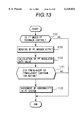
- FIG. 13 shows a flow chart in this case.
- the operation is composed of a step 1121 of judging whether or not the operation is during fuel pressure feedback control, a step 1122 of reading output of the fuel pressure sensor, a step 1123 of calculation of duty of the fuel pressure regulator, a step 1124 of viewing continuation of FPMIN>AVEPF or FPMAX ⁇ AVEPF for NGTIME (predetermined time) and a step 1125 of judging abnormality of the fuel pressure system by the result.
- FIG. 14 is a flow chart showing measures to be taken when the fuel pressure control system was judged to be abnormal.
- step 1141 of fuel pressure control system abnormality judgement the operation is switched to fuel pressure correction open control at step 1142, the variable fuel pressure regulator is switched to variable fuel pressure regulator duty open control at step 1143, and then fail-safe control is effected at step 1144.
- air fuel ratio learning is cleared, that is, an on-board control result of air fuel ratio is initialized, and renewal is inhibited. Further, lean operation is exhibited, the alarm raises an alarm, for example, an alarm light is lighted on.
- accident judgement of the fuel pressure control system can be effected before reaching an accident level, as mentioned above, additionally, the judgement is effected under the condition of accident detection of a predetermined time within a time of period from a time at which the fuel pressure sensor goes out of the dead zone to a time at which the pressure sensor reach the accident level, so that accident judgement of the fuel pressure control system can be effected with very less erroneous judgement.
Landscapes
- Engineering & Computer Science (AREA)
- Chemical & Material Sciences (AREA)
- Combustion & Propulsion (AREA)
- Mechanical Engineering (AREA)
- General Engineering & Computer Science (AREA)
- Electrical Control Of Air Or Fuel Supplied To Internal-Combustion Engine (AREA)
- Fuel-Injection Apparatus (AREA)
- Combined Controls Of Internal Combustion Engines (AREA)
Abstract
Description
Claims (10)
Applications Claiming Priority (2)
| Application Number | Priority Date | Filing Date | Title |
|---|---|---|---|
| JP9-357694 | 1997-12-25 | ||
| JP35769497A JP3709065B2 (en) | 1997-12-25 | 1997-12-25 | Engine fuel supply device |
Publications (1)
| Publication Number | Publication Date |
|---|---|
| US6125832A true US6125832A (en) | 2000-10-03 |
Family
ID=18455434
Family Applications (1)
| Application Number | Title | Priority Date | Filing Date |
|---|---|---|---|
| US09/220,800 Expired - Lifetime US6125832A (en) | 1997-12-25 | 1998-12-28 | Engine fuel supply apparatus |
Country Status (3)
| Country | Link |
|---|---|
| US (1) | US6125832A (en) |
| JP (1) | JP3709065B2 (en) |
| DE (1) | DE19859913B4 (en) |
Cited By (9)
| Publication number | Priority date | Publication date | Assignee | Title |
|---|---|---|---|---|
| US20040237937A1 (en) * | 2001-09-12 | 2004-12-02 | Klaus Joos | Method, computer programme, control and/or regulation device for operation of an internal combustion engine and fuel system for an internal combustion engine |
| US20050263146A1 (en) * | 2004-05-28 | 2005-12-01 | Mitsubishi Denki Kabushiki Kaisha | Fuel pressure control device for internal combustion engine |
| US20080035122A1 (en) * | 2006-08-09 | 2008-02-14 | Joseph Thomas | Fuel Delivery Control for Internal Combustion Engine |
| US20100010726A1 (en) * | 2008-07-11 | 2010-01-14 | Denso Corporation | Controller for internal combustion engine |
| US20120048242A1 (en) * | 2010-08-24 | 2012-03-01 | Ford Global Technologies, Llc | Fuel system for a multi-fuel engine |
| US20120291754A1 (en) * | 2011-05-19 | 2012-11-22 | Mitsubishi Electric Corporation | Fuel pump control apparatus of engine |
| US20150159577A1 (en) * | 2013-12-09 | 2015-06-11 | Aisan Kogyo Kabushiki Kaisha | Fuel supply system |
| US20160153371A1 (en) * | 2016-02-09 | 2016-06-02 | Caterpillar Inc. | Gas regulator for a multi-fuel engine and method of operating same |
| US20180128188A1 (en) * | 2015-05-26 | 2018-05-10 | Denso Corporation | High-pressure pump control device for internal combustion engine |
Families Citing this family (8)
| Publication number | Priority date | Publication date | Assignee | Title |
|---|---|---|---|---|
| DE19937962A1 (en) * | 1999-08-11 | 2001-02-15 | Bosch Gmbh Robert | IC engine common-rail fuel injection system control method monitors valve inserted between high pressure and low pressure regions for indicating fault |
| DE10126617B4 (en) | 2001-05-31 | 2005-05-25 | Siemens Ag | fuel supply |
| EP2123890A1 (en) * | 2008-05-21 | 2009-11-25 | GM Global Technology Operations, Inc. | A method and system for controlling operating pressure in a common-rail fuel injection system, particularly for a diesel engine |
| JP5126102B2 (en) * | 2009-02-10 | 2013-01-23 | トヨタ自動車株式会社 | Fuel supply device for internal combustion engine |
| JP5525760B2 (en) * | 2009-06-01 | 2014-06-18 | 日立オートモティブシステムズ株式会社 | High pressure fuel supply device for internal combustion engine |
| JP4952773B2 (en) * | 2009-11-04 | 2012-06-13 | トヨタ自動車株式会社 | Abnormality diagnosis device for fuel pressure sensor |
| JP5278290B2 (en) * | 2009-11-27 | 2013-09-04 | 株式会社デンソー | Failure diagnosis device for fuel injection system |
| DE102010031220A1 (en) * | 2010-07-12 | 2012-01-12 | Robert Bosch Gmbh | Method and apparatus for operating a fuel injection system |
Citations (4)
| Publication number | Priority date | Publication date | Assignee | Title |
|---|---|---|---|---|
| US5181499A (en) * | 1991-03-08 | 1993-01-26 | Toyota Jidosha Kabushiki Kaisha | Apparatus for diagnosing abnormality in fuel injection system and fuel injection control system having the apparatus |
| US5609140A (en) * | 1994-12-23 | 1997-03-11 | Robert Bosch Gmbh | Fuel supply system for an internal combustion engine |
| JPH09119335A (en) * | 1995-10-27 | 1997-05-06 | Isuzu Motors Ltd | Engine fuel supply control device |
| US5947098A (en) * | 1996-11-01 | 1999-09-07 | Hitachi, Ltd. | Engine control apparatus |
Family Cites Families (4)
| Publication number | Priority date | Publication date | Assignee | Title |
|---|---|---|---|---|
| DE19520300A1 (en) * | 1995-06-02 | 1996-12-05 | Bosch Gmbh Robert | Device for detecting a leak in a fuel supply system |
| DE19521791A1 (en) * | 1995-06-15 | 1996-12-19 | Daimler Benz Ag | Method for detecting malfunctions in a fuel injection system of an internal combustion engine |
| DE19622757B4 (en) * | 1995-11-09 | 2007-05-10 | Robert Bosch Gmbh | Method and device for detecting a leak in a fuel supply system of a high-pressure injection internal combustion engine |
| DE19634982C2 (en) * | 1996-08-29 | 2002-10-10 | Siemens Ag | Method for monitoring a fuel pressure |
-
1997
- 1997-12-25 JP JP35769497A patent/JP3709065B2/en not_active Expired - Fee Related
-
1998
- 1998-12-23 DE DE19859913A patent/DE19859913B4/en not_active Expired - Fee Related
- 1998-12-28 US US09/220,800 patent/US6125832A/en not_active Expired - Lifetime
Patent Citations (4)
| Publication number | Priority date | Publication date | Assignee | Title |
|---|---|---|---|---|
| US5181499A (en) * | 1991-03-08 | 1993-01-26 | Toyota Jidosha Kabushiki Kaisha | Apparatus for diagnosing abnormality in fuel injection system and fuel injection control system having the apparatus |
| US5609140A (en) * | 1994-12-23 | 1997-03-11 | Robert Bosch Gmbh | Fuel supply system for an internal combustion engine |
| JPH09119335A (en) * | 1995-10-27 | 1997-05-06 | Isuzu Motors Ltd | Engine fuel supply control device |
| US5947098A (en) * | 1996-11-01 | 1999-09-07 | Hitachi, Ltd. | Engine control apparatus |
Cited By (18)
| Publication number | Priority date | Publication date | Assignee | Title |
|---|---|---|---|---|
| US20040237937A1 (en) * | 2001-09-12 | 2004-12-02 | Klaus Joos | Method, computer programme, control and/or regulation device for operation of an internal combustion engine and fuel system for an internal combustion engine |
| US7171952B2 (en) | 2001-09-12 | 2007-02-06 | Robert Bosch Gmbh | Method, computer program, control and/or regulation device for operation of an internal combustion engine and fuel system for an internal combustion engine |
| US20050263146A1 (en) * | 2004-05-28 | 2005-12-01 | Mitsubishi Denki Kabushiki Kaisha | Fuel pressure control device for internal combustion engine |
| US7025050B2 (en) * | 2004-05-28 | 2006-04-11 | Mitsubishi Denki Kabushiki Kaisha | Fuel pressure control device for internal combination engine |
| US20080035122A1 (en) * | 2006-08-09 | 2008-02-14 | Joseph Thomas | Fuel Delivery Control for Internal Combustion Engine |
| US7765991B2 (en) | 2006-08-09 | 2010-08-03 | Ford Global Technologies, Llc | Fuel delivery control for internal combustion engine |
| US20100010726A1 (en) * | 2008-07-11 | 2010-01-14 | Denso Corporation | Controller for internal combustion engine |
| US7909020B2 (en) | 2008-07-11 | 2011-03-22 | Denso Corporation | Controller for internal combustion engine |
| US20120048242A1 (en) * | 2010-08-24 | 2012-03-01 | Ford Global Technologies, Llc | Fuel system for a multi-fuel engine |
| US8590510B2 (en) * | 2010-08-24 | 2013-11-26 | Ford Global Technologies, Llc | Fuel system for a multi-fuel engine |
| US9273654B2 (en) | 2010-08-24 | 2016-03-01 | Ford Global Technologies, Llc | Fuel system for a multi-fuel engine |
| US20120291754A1 (en) * | 2011-05-19 | 2012-11-22 | Mitsubishi Electric Corporation | Fuel pump control apparatus of engine |
| US9284907B2 (en) * | 2011-05-19 | 2016-03-15 | Mitsubishi Electric Corporation | Fuel pump control apparatus of engine |
| US20150159577A1 (en) * | 2013-12-09 | 2015-06-11 | Aisan Kogyo Kabushiki Kaisha | Fuel supply system |
| US9546616B2 (en) * | 2013-12-09 | 2017-01-17 | Aisan Kogyo Kabushiki Kaisha | Fuel supply system |
| US20180128188A1 (en) * | 2015-05-26 | 2018-05-10 | Denso Corporation | High-pressure pump control device for internal combustion engine |
| US10273885B2 (en) * | 2015-05-26 | 2019-04-30 | Denso Corporation | High-pressure pump control device for internal-combustion engine |
| US20160153371A1 (en) * | 2016-02-09 | 2016-06-02 | Caterpillar Inc. | Gas regulator for a multi-fuel engine and method of operating same |
Also Published As
| Publication number | Publication date |
|---|---|
| DE19859913B4 (en) | 2006-11-23 |
| JPH11190240A (en) | 1999-07-13 |
| DE19859913A1 (en) | 1999-07-08 |
| JP3709065B2 (en) | 2005-10-19 |
Similar Documents
| Publication | Publication Date | Title |
|---|---|---|
| US6125832A (en) | Engine fuel supply apparatus | |
| EP1205657B1 (en) | Method of diagnosing leakage in an internal combustion engine common-rail injection system | |
| US7489997B2 (en) | Diagnostic apparatus for internal combustion engine | |
| JP3884577B2 (en) | Control device for internal combustion engine | |
| EP0769612B1 (en) | Apparatus for detecting intake pressure abnormalities in an engine | |
| US6192866B1 (en) | Diagnosis for detecting freezing condition in intake pressure sensor | |
| JPH0799123B2 (en) | EGR system abnormality detection device | |
| US5567873A (en) | Misfire-determining controller for internal combustion engine | |
| US5735121A (en) | Air pump abnormality-detecting system for internal combustion engines | |
| US5531069A (en) | Catalyst deterioration-determining device of an internal combustion engine | |
| US20040112126A1 (en) | Diagnosis apparatus and method of fuel pump for internal combustion engine | |
| JP3871168B2 (en) | Engine fuel supply diagnostic apparatus, diagnostic method and fuel supply apparatus | |
| JPH10184479A (en) | Failure diagnosis device for fuel level detection means | |
| GB2339031A (en) | Determining proper functioning of an EGR system in an automotive engine | |
| JP2007085176A (en) | Diagnosis of fuel injection valve failure by cylinder | |
| JPS58101244A (en) | Abnormality detecting method and treating method of suction tube pressure signal | |
| JP3972604B2 (en) | In-cylinder direct injection internal combustion engine fuel system diagnostic device | |
| JP3864525B2 (en) | Engine fuel supply diagnostic apparatus and method | |
| EP2742217B1 (en) | Internal combustion engine control apparatus and internal combustion engine control method | |
| JP3754212B2 (en) | Warning light failure diagnosis device and method for internal combustion engine, and control method at failure | |
| JP3227912B2 (en) | Air-fuel ratio sensor deterioration determination control device | |
| US7313912B2 (en) | Secondary air supply system for internal combustion engine | |
| JP2601383B2 (en) | Self-diagnosis device in secondary air supply device of internal combustion engine | |
| JPH0532574B2 (en) | ||
| JP3663870B2 (en) | In-cylinder injection internal combustion engine control device |
Legal Events
| Date | Code | Title | Description |
|---|---|---|---|
| AS | Assignment |
Owner name: HITACHI CAR ENGINEERING CO., LTD., JAPAN Free format text: ASSIGNMENT OF ASSIGNORS INTEREST;ASSIGNORS:TOYOHARA, MASAHIRO;ATAGO, TAKESHI;HORI, TOSHIO;REEL/FRAME:009687/0296 Effective date: 19981204 Owner name: HITACHI, LTD., JAPAN Free format text: ASSIGNMENT OF ASSIGNORS INTEREST;ASSIGNORS:TOYOHARA, MASAHIRO;ATAGO, TAKESHI;HORI, TOSHIO;REEL/FRAME:009687/0296 Effective date: 19981204 |
|
| STCF | Information on status: patent grant |
Free format text: PATENTED CASE |
|
| FEPP | Fee payment procedure |
Free format text: PAYOR NUMBER ASSIGNED (ORIGINAL EVENT CODE: ASPN); ENTITY STATUS OF PATENT OWNER: LARGE ENTITY |
|
| FPAY | Fee payment |
Year of fee payment: 4 |
|
| FPAY | Fee payment |
Year of fee payment: 8 |
|
| FEPP | Fee payment procedure |
Free format text: PAYER NUMBER DE-ASSIGNED (ORIGINAL EVENT CODE: RMPN); ENTITY STATUS OF PATENT OWNER: LARGE ENTITY |
|
| FEPP | Fee payment procedure |
Free format text: PAYOR NUMBER ASSIGNED (ORIGINAL EVENT CODE: ASPN); ENTITY STATUS OF PATENT OWNER: LARGE ENTITY |
|
| FPAY | Fee payment |
Year of fee payment: 12 |