US6122977A - Impeller torque measuring device - Google Patents
Impeller torque measuring device Download PDFInfo
- Publication number
- US6122977A US6122977A US09/021,936 US2193698A US6122977A US 6122977 A US6122977 A US 6122977A US 2193698 A US2193698 A US 2193698A US 6122977 A US6122977 A US 6122977A
- Authority
- US
- United States
- Prior art keywords
- shaft
- torque
- motor
- transducer
- impeller
- Prior art date
- Legal status (The legal status is an assumption and is not a legal conclusion. Google has not performed a legal analysis and makes no representation as to the accuracy of the status listed.)
- Expired - Lifetime
Links
- 239000012530 fluid Substances 0.000 claims abstract description 6
- 239000007787 solid Substances 0.000 claims 5
- 239000011236 particulate material Substances 0.000 claims 4
- 239000013590 bulk material Substances 0.000 abstract description 2
- 239000000463 material Substances 0.000 description 3
- 239000002245 particle Substances 0.000 description 2
- 238000007789 sealing Methods 0.000 description 2
- 230000001133 acceleration Effects 0.000 description 1
- 238000006243 chemical reaction Methods 0.000 description 1
- 230000008878 coupling Effects 0.000 description 1
- 238000010168 coupling process Methods 0.000 description 1
- 238000005859 coupling reaction Methods 0.000 description 1
- 238000006073 displacement reaction Methods 0.000 description 1
- 238000011156 evaluation Methods 0.000 description 1
- 238000005259 measurement Methods 0.000 description 1
Images


Classifications
-
- G—PHYSICS
- G01—MEASURING; TESTING
- G01F—MEASURING VOLUME, VOLUME FLOW, MASS FLOW OR LIQUID LEVEL; METERING BY VOLUME
- G01F1/00—Measuring the volume flow or mass flow of fluid or fluent solid material wherein the fluid passes through a meter in a continuous flow
- G01F1/76—Devices for measuring mass flow of a fluid or a fluent solid material
- G01F1/78—Direct mass flowmeters
- G01F1/80—Direct mass flowmeters operating by measuring pressure, force, momentum, or frequency of a fluid flow to which a rotational movement has been imparted
- G01F1/84—Coriolis or gyroscopic mass flowmeters
- G01F1/845—Coriolis or gyroscopic mass flowmeters arrangements of measuring means, e.g., of measuring conduits
- G01F1/8454—Coriolis or gyroscopic mass flowmeters arrangements of measuring means, e.g., of measuring conduits rotating or rotatingly suspended measuring conduits
-
- G—PHYSICS
- G01—MEASURING; TESTING
- G01F—MEASURING VOLUME, VOLUME FLOW, MASS FLOW OR LIQUID LEVEL; METERING BY VOLUME
- G01F1/00—Measuring the volume flow or mass flow of fluid or fluent solid material wherein the fluid passes through a meter in a continuous flow
- G01F1/76—Devices for measuring mass flow of a fluid or a fluent solid material
- G01F1/78—Direct mass flowmeters
- G01F1/80—Direct mass flowmeters operating by measuring pressure, force, momentum, or frequency of a fluid flow to which a rotational movement has been imparted
Definitions
- the present invention relates to an apparatus for measuring a mass flow, in particular bulk material or a fluid, and the invention especially relates to an impeller torque measuring device used in a measuring device in which the mass flow rate is measured by using the Coriolis measuring principle.
- the particles to be measured are subjected to tangential acceleration in a whirling impeller, and the torque exerted on the vanes of the impeller in reaction to the Coriolis force of accelerated particles is being measured as an indication of the mass flow rate.
- the object of our above European patent application was to avoid measurement errors, due to uneven distribution of the material to be measured.
- the object of the present invention is to provide a device for accurately measuring the torque exerted by the material on the impeller vanes.
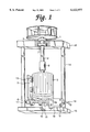
- FIG. 1 shows a schematic perspective view of part of a mass flow measuring device including an impeller with its drive shaft, drive motor and torque measuring device according to a first embodiment of the invention
- FIG. 2 shows a view corresponding to FIG. 1 of a second embodiment of the invention
- FIG. 3 shows a perspective view of the torque transducer used in the device according to FIG. 1.
- the part of the device shown in FIG. 1 is intended to be a part of a complete device for measuring a mass flow of the kind described in our copending European patent application No. 96850202.1, but in this Fig. is only shown the impeller 1 and its drive and torque measuring devices.
- the other parts relating to the measuring device can have the same, but also alternative, designs as those shown in our previous application.
- the impeller 1 is mounted for rotation on a vertical shaft 2, driven by an electric motor 3, wherein the shaft 2 and the motor 3 are located under the impeller 1.
- the impeller 1 is mounted on the upper end of the shaft 2 and the motor 3 on the other end.
- Under the motor 3 a torque transducer 4a is located.
- the shaft 2 is journalled in a thrust bearing 5, supported by a bearing cage 16 which in its turn by means of two columns 14 is connected to a base frame 15, supporting the complete measuring device.
- a radial bearing 7 is journalling the shaft 2 in the radial direction in the bearing cage 16, and is thus preventing the shaft 2 and the motor 3 from radial displacement.
- the shaft 2 is by means of a coupling 8 connected to the motor shaft of the motor 3.
- the base frame 15, the two columns 14 and the bearing cage 16 together form a stand for the measuring device.
- a transfer part 6 rigid in the horizontal plane is connected on the motor body.
- the transfer part 6 is preferably made integral with the torque transducer 4a, and the transfer part 6 and the torque transducer 4a are interconnected by a torque measuring section 10, comprising a strain gauge 11 for measuring the torque exerted by the motor 3 on the fastening plate 9 and the transfer part 6.
- the torque transducer 4a is by a connection cable 19 connected to an electronic device, not shown, e.g. a micro computer for evaluation of the torque signal and for controlling the measuring device.
- the body of the torque transducer 4a is attached to an angle bar 18 by means of attachment bolts 12, and the angle bar 18 is attached to the base frame 15.
- the torque measuring device shown in FIG. 1 is made with a weak fixation in vertical direction, meaning that the torque transducer 4a can not to carry thrust loads from the motor 3 and the impeller 1.
- the transfer part 6 can only carry loads in the horizontal plane, and has no ability to carry loads in the vertical plane.
- FIG. 2 is shown a torque measuring device essentially corresponding to the one shown in FIG. 1, but differing in that the torque transducer 4b is made to also be able to carry thrust loads from the motor 3 and the impeller 1.
- the impeller 1 is in this case not supported on the bearing cage 16, as there is no thrust bearing for supporting the weight of the impeller and the electric motor 3.
- the transfer part 6, also in this case made integral with the torque transducer 4b, is here made of a material having about the same stiffness in horizontal and vertical directions.
- FIG. 3 shows in detail the torque transducer 4a.
- the transfer part 6 In one end of the torque transducer 4a the transfer part 6 is located, which ends by a threaded stud 23, which by means of a threaded nut 17 can be secured to the fastening plate 9 for fastening the torque transducer to the motor 3.
- the transfer part 6 can be perforated by holes 24, for making the transfer part weaker in vertical direction.
- a connection plane 21 is located, in which threaded connection holes 22 are made for attaching the torque transducer 4a the angle bar 18 by means of the attachment bolts 12 screwed into the threaded connection holes 22.
- connection wire 19 is connected to the torque transducer 4a, and entering into the torque transducer 4a through a sealing sleeve 20.
- the torque measuring section 10, including the strain gauge 11 is covered by a pair of sealing bellows 25, to protect the strain gauge 11 from external influence.
- the shaft and the motor can also be mounted in the stand so that they are both axially and radially journalled in the motor end of the shaft, not shown in the drawings.
- the torque exerted on the motor is transferred to the torque transducer by means of a mechanical torque transferring device, such as a flexible torque shaft or a parallelogram.
Landscapes
- Physics & Mathematics (AREA)
- Fluid Mechanics (AREA)
- General Physics & Mathematics (AREA)
- Force Measurement Appropriate To Specific Purposes (AREA)
- Measuring Volume Flow (AREA)
Abstract
Description
Claims (10)
Applications Claiming Priority (2)
| Application Number | Priority Date | Filing Date | Title |
|---|---|---|---|
| EP97850020 | 1997-02-11 | ||
| EP97850020A EP0857952B1 (en) | 1997-02-11 | 1997-02-11 | Impeller torque measuring device |
Publications (1)
| Publication Number | Publication Date |
|---|---|
| US6122977A true US6122977A (en) | 2000-09-26 |
Family
ID=8230949
Family Applications (1)
| Application Number | Title | Priority Date | Filing Date |
|---|---|---|---|
| US09/021,936 Expired - Lifetime US6122977A (en) | 1997-02-11 | 1998-02-11 | Impeller torque measuring device |
Country Status (4)
| Country | Link |
|---|---|
| US (1) | US6122977A (en) |
| EP (1) | EP0857952B1 (en) |
| DE (1) | DE69737587T2 (en) |
| ES (1) | ES2285725T3 (en) |
Cited By (4)
| Publication number | Priority date | Publication date | Assignee | Title |
|---|---|---|---|---|
| US20060042401A1 (en) * | 2002-11-13 | 2006-03-02 | Jens Kahle | Measuring device for determining the mass rate of flow of a mass flow |
| US20080223624A1 (en) * | 2005-04-22 | 2008-09-18 | Schenck Process Gmbh | Bulk Material Storage Container |
| CN102829908A (en) * | 2012-08-27 | 2012-12-19 | 哈尔滨工业大学 | Method for measuring comprehensive interference torque of three-axis air-floating platform |
| WO2020060876A1 (en) * | 2018-09-19 | 2020-03-26 | Baker Hughes, A Ge Company, Llc | Torque-thrust chamber for horizontal pump test systems |
Families Citing this family (3)
| Publication number | Priority date | Publication date | Assignee | Title |
|---|---|---|---|---|
| DE19905951A1 (en) * | 1999-02-12 | 2000-08-17 | Schenck Process Gmbh | Device for measuring a mass flow |
| DE10336941B9 (en) * | 2003-08-07 | 2005-03-24 | Törner, Ludger | Device for measuring a mass flow according to the Coriolis measuring principle |
| DE102017217849A1 (en) * | 2017-02-01 | 2018-08-02 | GeMa Anlagentechnik GmbH & Co. KG | Elevator torque scale for detecting moving flow rates as well as methods for conveying goods |
Citations (5)
| Publication number | Priority date | Publication date | Assignee | Title |
|---|---|---|---|---|
| US2771773A (en) * | 1952-05-10 | 1956-11-27 | Wallace & Tiernan Inc | Measurement of mass rate of flow of fluent material |
| US2771772A (en) * | 1953-04-13 | 1956-11-27 | Wallace & Tieman Inc | Apparatus for measuring the mass rate of flow |
| EP0196440A1 (en) * | 1985-03-06 | 1986-10-08 | Klöckner Cra Patent Gmbh | Device for measuring mass flow |
| EP0474121A2 (en) * | 1990-09-04 | 1992-03-11 | Applikations- Und Technikzentrum Für Energieverfahrens-, Umwelt-, Und Strömungstechnik | Mass flow measuring device |
| EP0590187A1 (en) * | 1992-09-30 | 1994-04-06 | Carl Schenck Ag | Device for mass flow measurement |
Family Cites Families (1)
| Publication number | Priority date | Publication date | Assignee | Title |
|---|---|---|---|---|
| DE4134318A1 (en) * | 1991-10-17 | 1993-04-22 | Pfister Gmbh | DEVICE FOR MEASURING A MASS FLOW ACCORDING TO THE CORIOLIS PRINCIPLE |
-
1997
- 1997-02-11 ES ES97850020T patent/ES2285725T3/en not_active Expired - Lifetime
- 1997-02-11 DE DE69737587T patent/DE69737587T2/en not_active Expired - Lifetime
- 1997-02-11 EP EP97850020A patent/EP0857952B1/en not_active Expired - Lifetime
-
1998
- 1998-02-11 US US09/021,936 patent/US6122977A/en not_active Expired - Lifetime
Patent Citations (7)
| Publication number | Priority date | Publication date | Assignee | Title |
|---|---|---|---|---|
| US2771773A (en) * | 1952-05-10 | 1956-11-27 | Wallace & Tiernan Inc | Measurement of mass rate of flow of fluent material |
| US2771772A (en) * | 1953-04-13 | 1956-11-27 | Wallace & Tieman Inc | Apparatus for measuring the mass rate of flow |
| EP0196440A1 (en) * | 1985-03-06 | 1986-10-08 | Klöckner Cra Patent Gmbh | Device for measuring mass flow |
| US4700578A (en) * | 1985-03-06 | 1987-10-20 | Klockner Cra Technologie Gmbh | Apparatus for measuring a bulk stream |
| EP0474121A2 (en) * | 1990-09-04 | 1992-03-11 | Applikations- Und Technikzentrum Für Energieverfahrens-, Umwelt-, Und Strömungstechnik | Mass flow measuring device |
| US5191802A (en) * | 1990-09-04 | 1993-03-09 | Applikations und Technikzentrum fur Energieverfahrens, Umwelt und Stromungstechnik | Device for measuring mass flow |
| EP0590187A1 (en) * | 1992-09-30 | 1994-04-06 | Carl Schenck Ag | Device for mass flow measurement |
Cited By (8)
| Publication number | Priority date | Publication date | Assignee | Title |
|---|---|---|---|---|
| US20060042401A1 (en) * | 2002-11-13 | 2006-03-02 | Jens Kahle | Measuring device for determining the mass rate of flow of a mass flow |
| US7168328B2 (en) * | 2002-11-13 | 2007-01-30 | Schenck Process Gmbh | Measuring device for determining the mass rate of flow of a mass flow |
| US20080223624A1 (en) * | 2005-04-22 | 2008-09-18 | Schenck Process Gmbh | Bulk Material Storage Container |
| CN102829908A (en) * | 2012-08-27 | 2012-12-19 | 哈尔滨工业大学 | Method for measuring comprehensive interference torque of three-axis air-floating platform |
| WO2020060876A1 (en) * | 2018-09-19 | 2020-03-26 | Baker Hughes, A Ge Company, Llc | Torque-thrust chamber for horizontal pump test systems |
| GB2591944A (en) * | 2018-09-19 | 2021-08-11 | Baker Hughes Holdings Llc | Torque-thrust chamber for horizontal pump test systems |
| GB2591944B (en) * | 2018-09-19 | 2022-10-26 | Baker Hughes Holdings Llc | Torque-thrust chamber for horizontal pump test systems |
| US11493049B2 (en) | 2018-09-19 | 2022-11-08 | Baker Hughes Holdings Llc | Torque-thrust chamber for horizontal pump test systems |
Also Published As
| Publication number | Publication date |
|---|---|
| EP0857952B1 (en) | 2007-04-11 |
| DE69737587D1 (en) | 2007-05-24 |
| DE69737587T2 (en) | 2007-12-13 |
| EP0857952A1 (en) | 1998-08-12 |
| ES2285725T3 (en) | 2007-11-16 |
Similar Documents
| Publication | Publication Date | Title |
|---|---|---|
| US5353647A (en) | Apparatus for measuring Coriolis forces for ascertaining a mass flow, especially a bulk material flow | |
| US5450761A (en) | Torque meter | |
| US6122977A (en) | Impeller torque measuring device | |
| CA2107794A1 (en) | Axially compact torque transducer | |
| CN109596255A (en) | Measure device, wind-driven generator operation method and the wind-driven generator of wind-driven generator torque | |
| CN102706496B (en) | For measuring the device of the uneven power produced | |
| JP4344096B2 (en) | A device for measuring the force generated by rotor imbalance | |
| US4445372A (en) | Balancing machine for bodies of rotation | |
| US5445036A (en) | Torque sensor | |
| JP4539945B2 (en) | Torque measuring device for a device measuring material flow | |
| CN107560859B (en) | Test device for back-to-back testing of turbomachines | |
| EP0845662B1 (en) | Apparatus for measuring the mass rate of flow | |
| KR100782206B1 (en) | Device for measuring loads caused by rotor imbalance | |
| CN109357808B (en) | Test platform for testing excitation force of underwater impeller | |
| CN109506823B (en) | Radial force measuring device of fan blade in rotation state | |
| JP3904600B2 (en) | Support system with wire suspension fixed in radial direction | |
| CN106769849A (en) | The experimental rig of coated substrate interface tension strength test under a kind of shear stress | |
| CA1320846C (en) | Chip level indicator with differential transformer | |
| US3742758A (en) | Torque reaction table | |
| US2896450A (en) | Mass flowmeter | |
| CN215003811U (en) | An absolute pressure level gauge for water services | |
| RU2337336C2 (en) | Test bench for control and diagnostics | |
| SU1638575A1 (en) | Device for measuring efforts at rotary working member | |
| CN110132560A (en) | A kind of shafting vibration integrated monitor auxiliary device | |
| CN116858323A (en) | Method and structure for counteracting friction force in coriolis scale |
Legal Events
| Date | Code | Title | Description |
|---|---|---|---|
| AS | Assignment |
Owner name: S.E.G. MEKANIK AB, SWEDEN Free format text: ASSIGNMENT OF ASSIGNORS INTEREST;ASSIGNORS:SODERHOLM, ARNE;SODERHOLM, OLLE;REEL/FRAME:008984/0481 Effective date: 19980205 |
|
| STCF | Information on status: patent grant |
Free format text: PATENTED CASE |
|
| FEPP | Fee payment procedure |
Free format text: PAYOR NUMBER ASSIGNED (ORIGINAL EVENT CODE: ASPN); ENTITY STATUS OF PATENT OWNER: SMALL ENTITY Free format text: PAYER NUMBER DE-ASSIGNED (ORIGINAL EVENT CODE: RMPN); ENTITY STATUS OF PATENT OWNER: SMALL ENTITY |
|
| FPAY | Fee payment |
Year of fee payment: 4 |
|
| FPAY | Fee payment |
Year of fee payment: 8 |
|
| FPAY | Fee payment |
Year of fee payment: 12 |