US6122446A - Blur correction camera - Google Patents
Blur correction camera Download PDFInfo
- Publication number
- US6122446A US6122446A US09/299,433 US29943399A US6122446A US 6122446 A US6122446 A US 6122446A US 29943399 A US29943399 A US 29943399A US 6122446 A US6122446 A US 6122446A
- Authority
- US
- United States
- Prior art keywords
- blur
- arithmetic
- image
- movement amount
- image movement
- Prior art date
- Legal status (The legal status is an assumption and is not a legal conclusion. Google has not performed a legal analysis and makes no representation as to the accuracy of the status listed.)
- Expired - Lifetime
Links
Images


Classifications
-
- G—PHYSICS
- G03—PHOTOGRAPHY; CINEMATOGRAPHY; ANALOGOUS TECHNIQUES USING WAVES OTHER THAN OPTICAL WAVES; ELECTROGRAPHY; HOLOGRAPHY
- G03B—APPARATUS OR ARRANGEMENTS FOR TAKING PHOTOGRAPHS OR FOR PROJECTING OR VIEWING THEM; APPARATUS OR ARRANGEMENTS EMPLOYING ANALOGOUS TECHNIQUES USING WAVES OTHER THAN OPTICAL WAVES; ACCESSORIES THEREFOR
- G03B17/00—Details of cameras or camera bodies; Accessories therefor
-
- G—PHYSICS
- G02—OPTICS
- G02B—OPTICAL ELEMENTS, SYSTEMS OR APPARATUS
- G02B27/00—Optical systems or apparatus not provided for by any of the groups G02B1/00 - G02B26/00, G02B30/00
- G02B27/64—Imaging systems using optical elements for stabilisation of the lateral and angular position of the image
- G02B27/646—Imaging systems using optical elements for stabilisation of the lateral and angular position of the image compensating for small deviations, e.g. due to vibration or shake
-
- G—PHYSICS
- G03—PHOTOGRAPHY; CINEMATOGRAPHY; ANALOGOUS TECHNIQUES USING WAVES OTHER THAN OPTICAL WAVES; ELECTROGRAPHY; HOLOGRAPHY
- G03B—APPARATUS OR ARRANGEMENTS FOR TAKING PHOTOGRAPHS OR FOR PROJECTING OR VIEWING THEM; APPARATUS OR ARRANGEMENTS EMPLOYING ANALOGOUS TECHNIQUES USING WAVES OTHER THAN OPTICAL WAVES; ACCESSORIES THEREFOR
- G03B2217/00—Details of cameras or camera bodies; Accessories therefor
- G03B2217/005—Blur detection
Definitions
- the present invention relates to a blur correction camera having a function of sensing a camera shake of a photographer and correcting a blur due to the camera shake.
- Jpn. Pat. Appln. KOKAI Publication No. 9-304803 discloses a technique of reducing a blur display amount during the blur correction to about one-third a blur display amount not during the blur correction when a camera shake is sensed and its corresponding blur state is displayed in real time. According to this technique, a user can feel a camera performing a blur correcting operation even in a lens shutter camera or a wide-angle shot in which basically the user did not really feel a blur correcting operation in a finder optical system (prior art 1).
- a blur display amount is uniformly set to about one-third during the blur correction; however, the actual blur amount of an image formed on an image forming plane does not always correspond to the blur display amount.
- the blur display amount becomes larger or smaller than one-third of amount, depending upon the conditions (frequency and amplitude) of a camera shake and the states of a blur correction mechanism. The amount is therefore incorrect.
- the present invention has been developed in order to resolve the above problems and its object is to provide a blur correction camera capable of displaying an amount of image movement (blur) on an image forming plane more exactly based on the actual conditions of a camera shake and the operation states of a blur correcting member.
- a blur correction camera comprising a sensing member for sensing a camera shake, and arithmetic means for calculating a difference between a movement amount of an image on a film plane and a movement amount of a blur-corrected image on the film plane in response to an output of the sensing member to obtain an actual blur amount.
- a blur correction camera comprising sensing means for sensing a camera shake
- blur correcting means for correcting an amount of image movement due to the camera shake, first arithmetic means for calculating an image movement amount on a film plane in response to an output of the sensing means, second arithmetic means for calculating an image movement amount on the film plane in response to an output of the sensing means, when the image movement amount is corrected by the blur correcting means, and third arithmetic means for calculating a difference between an arithmetic result of the first arithmetic means and an arithmetic result of the second arithmetic means.
- a blur correction camera comprising sensing means for sensing a camera shake, blur correcting means for correcting an image blur due to the camera shake, by driving part of a shooting optical system, first arithmetic means for calculating an image movement amount on a film plane in response to an output of the sensing means when the image movement amount is not corrected, and outputting the image movement amount as a first arithmetic result, second arithmetic means for calculating an image movement amount on the film plane in response to the first arithmetic result when the image movement amount is corrected by the blur correcting means, and outputting the image movement amount as a second arithmetic result, third arithmetic means for calculating a difference between the first arithmetic result and the second arithmetic result and outputting the difference as a third arithmetic result, and display means for displaying the third arithmetic result as an actual blur amount for a predetermined period of time after completion of exposure.
- FIG. 1 is a conceptual diagram of a blur correction camera according to a first embodiment of the present invention
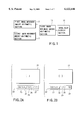
- FIG. 2A is a view showing an example of finder display of a image blur display section 13 of the blur correction camera according to the first embodiment
- FIG. 2B is a view of another example of finder display of the image blur display section 13;
- FIG. 3 is a block diagram showing a constitution of the blur correction camera of FIG. 1 more specifically;
- FIG. 4 is a flowchart showing a sequence of blur correcting operations for controlling a blur correcting operation, calculating an image movement amount and displaying an image blur in the blur correction camera of FIG. 1, the calculating and displaying operations being the features of the present invention
- FIG. 5 is a flowchart showing a sequence of blur correcting operations during the exposure which is executed by the blur correction camera according to the first embodiment
- FIG. 6 is a conceptual diagram of a blur correction camera according to a second embodiment of the present invention.
- FIG. 7 is a block diagram showing a constitution of the blur correction camera of FIG. 6 more specifically;
- FIG. 8 is a flowchart showing a sequence of blur correcting operations for controlling a blur correcting operation, calculating an image movement amount and displaying an image blur in the blur correction camera of FIG. 6, the calculating and displaying operations being the features of the present invention.
- FIG. 9 is a flowchart showing a sequence of blur correcting operations during the exposure which is executed by the blur correction camera according to the second embodiment.
- FIG. 1 is a conceptual diagram of a blur correction camera according to a first embodiment of the present invention.
- an output of a first image movement amount arithmetic section 2 serving as a first arithmetic means and that of a second image movement amount arithmetic section 9 serving as a second arithmetic means are connected to their respective inputs of a third image movement amount arithmetic section 12 serving as a third arithmetic means.
- An output of the section 12 is connected to an input of an image blur display section 13 serving as a display means.
- the first image movement amount arithmetic section 2 calculates an amount of image movement to be caused commonly based on the current camera shake conditions and focal length and exposure time information.
- the second image movement amount arithmetic section 9 calculates a degree of image movement based on information on an operation state (position) of a member to be driven for the blur correcting operation, such as a lens and a film.
- Arithmetic results of the first and second image movement amount arithmetic sections 2 and 9 are sent to the third image movement amount arithmetic section 12.
- the section 12 determines a difference between the arithmetic results of the two sections 2 and 9. The reason for this calculation is that the difference corresponds to the actual image movement amount remaining on an image forming plane.
- An arithmetic result of the third image movement amount arithmetic section 12 is transmitted to the image blur display section 13.
- the section 13 displays prescribed information on an actual image movement amount remaining on the image forming plane.
- the actual image movement amount remaining on the image forming plane can be displayed. Accordingly, a photographer sees the display and knows the actual state of an image.
- FIGS. 2A and 2B show examples of finder display of the image blur display section 13 described above.
- reference numeral 21 indicates a finder frame
- 22 shows a shooting information display section for displaying shooting information
- 23 represents an exposure time and aperture display section for displaying exposure time and an aperture
- 24 denotes a stroboscope charging display section for displaying a charging state of a stroboscope
- 25 indicates an AF display section for displaying an automatic focusing state
- 26 denotes a blur correction mechanism operation display section for displaying an operation of a blur correction mechanism.
- reference numeral 27 denotes a first image blur display section corresponding to the above image blur display section 13 and including well-known LEDs and LCDs.
- This display section displays the actual image blur state on three levels. For example, when an image blur is very large, all three LEDs turn on. When it is very small, only a left one of them turns on.
- reference numeral 28 represents a second image blur display section corresponding to the above image blur display section 13.
- This display section displays an absolute value (unit: ⁇ m) of the actual image movement amount remaining on an image forming plane. Needless to say, the larger the absolute value, the larger the actual image movement amount.
- FIG. 3 shows a constitution of the blur correction camera of FIG. 1 more specifically.
- FIGS. 1 and 3 denote the same constituting elements.
- an output of a camera shake sensing section 1 serving as a sensing means is connected to an input of the first image movement amount arithmetic section 2.
- An output of a focal length sensing section 7 and that of an exposure time setting section 8 are also connected to their respective inputs of the section 2.
- the output of the section 2 is connected to an input of a first image movement amount storage section 10 and that of a correcting member driving section 4 via a correction driving signal determination section 3.
- the section 4 is connected to a blur correcting member 5.
- a correction position sensing section 6 is arranged in the vicinity of the member 5. An output of the correction position sensing section 6 is fed back to an input of the correction driving signal determination section 3 and connected to an input of the second image movement arithmetic section 9.
- the output of the exposure time setting section 8 is also connected to the input of the section 9, and an output of the section 9 is connected to an input of a second image movement amount storing section 11.
- the outputs of the first and second image movement amount storage sections 10 and 11 are connected to the inputs of the third image movement amount arithmetic section 12, and the output of the section 12 is connected to an input of the image blur display section 13.
- the camera shake sensing section 1 senses a shake of a camera and, for example, a well-known constant angular velocity sensor (vibrating gyroscope) can be applied to the section 1.
- Camera shake information sensed by the camera shake sensing section 1 is sent to its subsequent first image movement amount arithmetic section 2.
- the section 2 is supplied with both shooting focal length information from the focal length sensing section 7 and exposure time information from the exposure time setting section 8, and calculates an amount of image movement to be caused normally based on these information and the foregoing camera shake information.
- the image movement amount information obtained by the first image movement amount arithmetic section 2 is sent to its subsequent correction driving signal determination section 3.
- the section 3 determines a driving signal for driving the blur correcting member 5 to actually carry out a blur correcting operation.
- the driving signal is determined by adding correction position information of a correction device (which will be described later) to the image movement amount information obtained by the first image movement amount arithmetic section 2.
- the driving signal determined by the correction driving signal determination section 3 is transmitted to the correcting member driving section 4.
- This section 4 is used to actually drive the blur correcting member 5, and a well-known actuator such as a DC motor and a voice coil can be applied to the section 4.
- the correcting member driving section 4 drives the blur correcting member 5 to actually correct an image blur.
- the member 5 part (lens) of the shooting optical system, a film serving as an image forming plane, etc., can be applied.
- An operation position of the blur correcting member 5 is sensed by the correction position sensing section 6.
- the section 6 is constituted of a well-known PI (photo-interrupter), a PR (photo-reflector) and the like.
- the sensing section 6 senses operation states of a series of gears and a reduction mechanism (neither of which is illustrated) which are interposed between the correcting member driving section 4 and blur correcting member 5.
- the information sensed by the section 6 is sent to the foregoing correction driving signal determination section 3 and used as a feedback signal for control of blur correction.
- the feedback signal is also sent to the second image movement amount arithmetic section 9.
- the section 9 obtains an amount of image movement caused only by the driving operation of the blur correcting member 5 based on both the operation position information of the member 5 from the correction position sensing section 6 and the exposure time information from the exposure time setting section 8.
- the image movement amounts obtained by the first and second image movement amount arithmetic sections 2 and 9 are temporarily stored in the first and second image movement amount storage sections 10 and 11, respectively, and read out of the third image movement amount arithmetic section 12.
- the section 12 determines a difference between arithmetic results of the two sections 2 and 9. The reason why the difference is determined has been described above.
- the actual image movement amount remaining on the image forming plane can be obtained from a difference between the results calculated by the first and second image movement amount arithmetic sections 2 and 9.
- An arithmetic result of the third image movement amount arithmetic section 12 is supplied to the image blur display section 13. Based on the result, the section 13 displays information about the actual image movement amount remaining on the image forming plane in such a manner as shown in FIGS. 2A and 2B.
- FIG. 3 illustrates one camera shake sensing section 1, one correcting member driving section 4 and one correction position sensing section 6; however, usually, the number of sections 1, that of sections 4, and that of sections 6 are each two in order that they can be adapted to two directions of a yaw direction (horizontal direction of the shooting plane) and a pitch direction (vertical direction thereof) of a camera body.
- the first, second and third image movement amount arithmetic sections 2, 9 and 12 each calculate an image movement amount in both the yaw and pitch directions, and finally the image blur display section 13 obtains a vector sum of the image movement amounts in the yaw and pitch directions to display an image blur.
- the flowchart of FIG. 4 is directed to a sequence of blur correcting operations for controlling a blur correcting operation, calculating an image movement amount and displaying an image blur.
- the calculating and displaying operations are the features of the present invention. This sequence is repeated when a blur correcting operation is performed by the camera.
- a periodic control timer for executing blur correction control in a fixed period starts (step S1).
- the timer makes the control stable, and time of about 1 mS can be set for the timer. It is needless to say that the present invention is not limited to this time.
- step S2 sampling of information on a camera shake sensed by the camera shake sensing section 1 is performed (step S2). Specifically, an output of the section 1 is A/D-converted and supplied into a blur correction control section (microcomputer), which is not shown.
- a blur correction control section microcomputer
- An amount of image movement caused by the camera shake is calculated from the camera shake information, the shooting focal length information and the set exposure time information which have already been obtained. This calculation is performed by the first image movement amount arithmetic section 2. In advance of the calculation, a filtering operation for removing unnecessary signal components and an integrating operation for converting velocity information on the sensed camera shake into displacement information (step S3).
- the image movement amount calculated in step S3 is stored in the first image movement amount storage section 10 (step S4).
- step S5 the current positional information of the blur correcting member 5 is confirmed on the basis of information output from the correction position sensing section 6 (step S5).
- step S8 the position of the member 5 is detected in step S8, which will be described later.
- the correction driving signal determination section 3 generates (determines) data for driving the blur correcting member 5 based on the image movement amount calculated in step S3 and the position of the blur correcting member 5 confirmed in step S5 (step S6). Subsequently, the correcting member driving section 4 drives the blur correcting member 5 based on the data determined in step S6 (step S7).
- the correction position sensing section 6 senses information on an operation position of the blur correcting member 5. This information is used for calculating an image movement amount in step S9 and also used as positional information for control of the blur correction in step S5 (used for executing this loop next time) (step S8).
- the second image movement amount arithmetic section 9 calculates an image movement amount corresponding to the set exposure time and obtained only by driving the blur correcting member 5, on the basis of the information of the member 5 sensed in step S8 (step S9).
- the calculated image movement amount is stored in the second image movement amount storage section 11 (step S10).
- the third image movement arithmetic section 12 determines a difference between the first and second image movement amounts stored in steps S4 and S10 (step S11). This difference corresponds to the present image movement amount remaining on the image forming plane, in spite of the blur correcting operation.
- the image blur display section 13 displays the image movement (blur) amount (step S12). This display pattern is the same as that described with reference to FIGS. 2A and 2B.
- step S1 It is then determined whether the periodic control timer started in step S1 has overflowed or whether a predetermined period of time has elapsed. If the timer has not overflowed, an operation of step S13 is repeated until it overflows. If the timer has overflowed, the flow returns to step S1.
- the flow is repeated during the blur correction.
- step S13 the flow is repeated from step S1.
- the above loop takes a short time (e.g., 1 mS) and the image blur display in step S12 can be changed frequently. Since, however, the frequent change in display is a nuisance, the display can be changed once every several tens to several hundreds of milliseconds (mS).
- step S21 First it is determined whether an instruction to start exposure is given or not (step S21). If there is no instruction, step S21 is repeated. If there is an instruction, the flow advances to the next step to start a blur correcting operation (step S22).
- step S23 an exposure operation is started (step S23) to continuously perform the blur correcting operation (step S24).
- step S24 basically the same operation as described above with reference to FIG. 4 is carried out, except for the display of an image movement amount using the image blur display section 13 in step S12 shown in FIG. 4.
- step S25 It is then determined whether a predetermined period of time has elapsed or not (step S25). If the time has not elapsed, the flow returns to step S24 to continuously perform the above blur correcting operation. If it has elapsed, the exposure is completed (step S26).
- step S27 the blur correcting operation is completed (step S27), and a value obtained by subtracting an amount of image movement caused by an operation of the blur correcting member during the exposure from that of image movement caused only by a camera shake during the exposure, or the actual image movement amount remaining on the image forming plane during the exposure is displayed (step S28).
- step S28 a value obtained by subtracting an amount of image movement caused by an operation of the blur correcting member during the exposure from that of image movement caused only by a camera shake during the exposure, or the actual image movement amount remaining on the image forming plane during the exposure.
- FIG. 6 is a conceptual diagram of the blur correction camera of the second embodiment of the present invention.
- the image blur display section 13 displays predetermined information on the actual image movement amount remaining on the image forming plane, based on information about arithmetic results.
- the second embodiment is featured in that the display section 13 is replaced with a notification section 100.
- the notification section 100 includes a display section and an alarm section (sound section). Assume that the notification section 100 is formed of a display section including a plurality of LEDs. The larger the actual blur amount, the more the LEDs turning on. If an alarm section is adopted in the notification section 100, an image blur is notified by, e.g., voice. The actual blur amount is displayed after exposure is completed. The plurality of LEDs are provided in a finder.
- the notification section 100 has the same feature as described above.
- step S14 differs from FIG. 4 corresponding to the first embodiment.
- the image blur display section 13 displays an image movement (blur) amount in reply to the arithmetic results of an image blur (step S12 in FIG. 4). Contrastingly, in step S14 of FIG. 8, an image movement amount is notified.
- This notification includes an alarm (sound) notification as well as the above display notification.
- step S29 differs from FIG. 5 corresponding to the first embodiment.
- a value obtained by subtracting an amount of image movement caused by an operation of the blur correcting member during the exposure from that of image movement caused only by a camera shake during the exposure, or the actual image movement amount remaining on the image forming plane during the exposure is displayed (step S28 in FIG. 5). This corresponds to the above-described step S12 in FIG. 4.
- a value obtained by subtracting an amount of image movement caused by an operation of the blur correcting member during the exposure from that of image movement caused only by a camera shake during the exposure, or the actual image movement amount remaining on the image forming plane during the exposure is notified (step S29 in FIG. 9).
- This notification includes a sound alarm and corresponds to the foregoing step S14 in FIG. 8.
- a value obtained by subtracting an amount of image movement caused by a blur correcting operation itself from that of image movement caused only by a camera shake is set as formed (remaining) image movement amount information, and this information is used for blur display. It is thus possible for a photographer to know the actual image movement (blur) amount on the image forming plane even in a blur correctable system. In view of this, the photographer can easily determine whether the current shooting is successful or whether the shooting should be performed again.
- the present invention since the actual image movement amount during the exposure is displayed after completion of the exposure, a user sees this display and knows how a just-taken picture is blurred.
- the present invention is not limited to the above embodiments. Various changes and modifications can be made without departing from the scope of the subject matter of the present invention.
- the present invention can be applied to not only an apparatus for correcting a blur by driving part of a lens but also a blur correction apparatus in which film driving prevents an image from moving due to a camera shake.
- a user cannot basically confirm a degree of blur correction through a finder image; therefore, the display of an image blur state in the present invention is considered to be very useful.
- a more exact image movement (blur) amount on the image forming plane can be displayed based on the actual states of a camera shake and a blur correcting member.
Abstract
Description
Claims (23)
Applications Claiming Priority (2)
| Application Number | Priority Date | Filing Date | Title |
|---|---|---|---|
| JP10-125911 | 1998-05-08 | ||
| JP10125911A JPH11326978A (en) | 1998-05-08 | 1998-05-08 | Blur correcting camera |
Publications (1)
| Publication Number | Publication Date |
|---|---|
| US6122446A true US6122446A (en) | 2000-09-19 |
Family
ID=14921976
Family Applications (1)
| Application Number | Title | Priority Date | Filing Date |
|---|---|---|---|
| US09/299,433 Expired - Lifetime US6122446A (en) | 1998-05-08 | 1999-04-26 | Blur correction camera |
Country Status (2)
| Country | Link |
|---|---|
| US (1) | US6122446A (en) |
| JP (1) | JPH11326978A (en) |
Cited By (12)
| Publication number | Priority date | Publication date | Assignee | Title |
|---|---|---|---|---|
| US20030079078A1 (en) * | 2001-10-19 | 2003-04-24 | Xerox Corporation | Confirmation of secure data file erasure |
| US20040056963A1 (en) * | 2002-09-24 | 2004-03-25 | Yoshikazu Ishikawa | Vibration correction for image sensing apparatus |
| US20040263635A1 (en) * | 2003-06-30 | 2004-12-30 | Kabushiki Kaisha Toshiba | Digital camera with a function of displaying the degree of hand tremble |
| US20050264654A1 (en) * | 2000-02-04 | 2005-12-01 | Kazuhiko Eto | Image sensing apparatus, control method of image sensing apparatus, and computer program product |
| US20050270409A1 (en) * | 2004-06-03 | 2005-12-08 | Canon Kabushiki Kaisha | Image pickup apparatus, image pickup method, program for implementing the method, and storage medium storing the program |
| US20060056831A1 (en) * | 2004-09-13 | 2006-03-16 | Konica Minolta Photo Imaging, Inc. | Digital camera |
| US20070115364A1 (en) * | 2005-11-11 | 2007-05-24 | Sony Corporation | Image processing apparatus and method, and program used therewith |
| US20140125834A1 (en) * | 2003-09-03 | 2014-05-08 | Canon Kabushiki Kaisha | Display apparatus, image processing apparatus, and image processing system |
| US8964045B2 (en) | 2012-01-31 | 2015-02-24 | Microsoft Corporation | Image blur detection |
| CN109983758A (en) * | 2016-12-02 | 2019-07-05 | 索尼半导体解决方案公司 | Image-forming component, imaging method and electronic equipment |
| US11134198B2 (en) * | 2019-03-05 | 2021-09-28 | Panasonic Intellectual Property Management Co., Ltd. | Imaging apparatus |
| US20230007155A1 (en) * | 2018-12-28 | 2023-01-05 | Canon Kabushiki Kaisha | Notifying apparatus, image capturing apparatus, notifying method, image capturing method, and storage medium |
Citations (5)
| Publication number | Priority date | Publication date | Assignee | Title |
|---|---|---|---|---|
| JPH09304803A (en) * | 1996-05-15 | 1997-11-28 | Canon Inc | Optical equipment |
| US5790490A (en) * | 1996-05-10 | 1998-08-04 | Olympus Optical Co., Ltd. | Anti-shake camera |
| US5842054A (en) * | 1996-09-20 | 1998-11-24 | Sony Corporation | Shake discrimination and image stabilizer |
| US5937214A (en) * | 1996-11-29 | 1999-08-10 | Minolta Co., Ltd. | Camera capable of correcting a shake |
| US6035130A (en) * | 1998-01-09 | 2000-03-07 | Olympus Optical Co., Ltd. | Camera with condition indication facility |
-
1998
- 1998-05-08 JP JP10125911A patent/JPH11326978A/en active Pending
-
1999
- 1999-04-26 US US09/299,433 patent/US6122446A/en not_active Expired - Lifetime
Patent Citations (5)
| Publication number | Priority date | Publication date | Assignee | Title |
|---|---|---|---|---|
| US5790490A (en) * | 1996-05-10 | 1998-08-04 | Olympus Optical Co., Ltd. | Anti-shake camera |
| JPH09304803A (en) * | 1996-05-15 | 1997-11-28 | Canon Inc | Optical equipment |
| US5842054A (en) * | 1996-09-20 | 1998-11-24 | Sony Corporation | Shake discrimination and image stabilizer |
| US5937214A (en) * | 1996-11-29 | 1999-08-10 | Minolta Co., Ltd. | Camera capable of correcting a shake |
| US6035130A (en) * | 1998-01-09 | 2000-03-07 | Olympus Optical Co., Ltd. | Camera with condition indication facility |
Cited By (20)
| Publication number | Priority date | Publication date | Assignee | Title |
|---|---|---|---|---|
| US20050264654A1 (en) * | 2000-02-04 | 2005-12-01 | Kazuhiko Eto | Image sensing apparatus, control method of image sensing apparatus, and computer program product |
| US7460155B2 (en) * | 2000-02-04 | 2008-12-02 | Canon Kabushiki Kaisha | Image sensing apparatus having an antivibration unit, control method of the image sensing apparatus, and computer program product |
| US20030079078A1 (en) * | 2001-10-19 | 2003-04-24 | Xerox Corporation | Confirmation of secure data file erasure |
| US7349118B2 (en) * | 2001-10-19 | 2008-03-25 | Xerox Corp. | Confirmation of secure data file erasure |
| US20040056963A1 (en) * | 2002-09-24 | 2004-03-25 | Yoshikazu Ishikawa | Vibration correction for image sensing apparatus |
| US7209165B2 (en) * | 2002-09-24 | 2007-04-24 | Canon Kabushiki Kaisha | Vibration correction for image sensing apparatus |
| US20040263635A1 (en) * | 2003-06-30 | 2004-12-30 | Kabushiki Kaisha Toshiba | Digital camera with a function of displaying the degree of hand tremble |
| US20140125834A1 (en) * | 2003-09-03 | 2014-05-08 | Canon Kabushiki Kaisha | Display apparatus, image processing apparatus, and image processing system |
| US9131122B2 (en) * | 2003-09-03 | 2015-09-08 | Canon Kabushiki Kaisha | Apparatus, method, system, and storage medium causing a display to display a graph indicating a degree of change of part of a captured image |
| US20050270409A1 (en) * | 2004-06-03 | 2005-12-08 | Canon Kabushiki Kaisha | Image pickup apparatus, image pickup method, program for implementing the method, and storage medium storing the program |
| US7545433B2 (en) * | 2004-06-03 | 2009-06-09 | Canon Kabushiki Kaisha | Image pickup apparatus, image pickup method, program for implementing the method, and storage medium storing the program |
| US20060056831A1 (en) * | 2004-09-13 | 2006-03-16 | Konica Minolta Photo Imaging, Inc. | Digital camera |
| US7636106B2 (en) * | 2005-11-11 | 2009-12-22 | Sony Corporation | Image processing apparatus and method, and program used therewith |
| US20070115364A1 (en) * | 2005-11-11 | 2007-05-24 | Sony Corporation | Image processing apparatus and method, and program used therewith |
| US8964045B2 (en) | 2012-01-31 | 2015-02-24 | Microsoft Corporation | Image blur detection |
| CN109983758A (en) * | 2016-12-02 | 2019-07-05 | 索尼半导体解决方案公司 | Image-forming component, imaging method and electronic equipment |
| US11095816B2 (en) * | 2016-12-02 | 2021-08-17 | Sony Semiconductor Solutions Corporation | Image pickup element, image pickup method, and electronic device for image stabilization |
| US20230007155A1 (en) * | 2018-12-28 | 2023-01-05 | Canon Kabushiki Kaisha | Notifying apparatus, image capturing apparatus, notifying method, image capturing method, and storage medium |
| US11818466B2 (en) * | 2018-12-28 | 2023-11-14 | Canon Kabushiki Kaisha | Notifying apparatus, image capturing apparatus, notifying method, image capturing method, and storage medium |
| US11134198B2 (en) * | 2019-03-05 | 2021-09-28 | Panasonic Intellectual Property Management Co., Ltd. | Imaging apparatus |
Also Published As
| Publication number | Publication date |
|---|---|
| JPH11326978A (en) | 1999-11-26 |
Similar Documents
| Publication | Publication Date | Title |
|---|---|---|
| JP2961761B2 (en) | Optical device | |
| US5337098A (en) | Camera-shake preventing device | |
| JP4981325B2 (en) | Camera system | |
| US5585875A (en) | Camera having anti-vibration function | |
| US6122446A (en) | Blur correction camera | |
| JPH07199257A (en) | Controller for preventing image blurring | |
| JPH07301836A (en) | Camera shake detecting device and camera shake preventing device using the same | |
| JP3376012B2 (en) | camera | |
| JPH0915670A (en) | Blurring correction optical device | |
| US6088533A (en) | Transmission apparatus for image blur prevention | |
| US6735383B2 (en) | Vibration correction apparatus, lens apparatus, and optical apparatus | |
| JPH04277728A (en) | Vibration-proof device for camera | |
| US6035133A (en) | Image blur prevention device | |
| JP3389617B2 (en) | Camera shake correction device | |
| JP3195483B2 (en) | Camera image stabilizer | |
| US6122448A (en) | Image blur prevention apparatus | |
| JPH06130446A (en) | Trimming camera | |
| US5752094A (en) | Autozoon apparatus for camera | |
| JP3096828B2 (en) | camera | |
| JP3360123B2 (en) | Image stabilization photographing device | |
| JP3235031B2 (en) | Camera shake display | |
| JP3531642B2 (en) | Interchangeable lens with image stabilization function | |
| JP3445334B2 (en) | Camera with shake correction | |
| JP2018194770A (en) | Camera system, interchangeable and camera | |
| JP3198339B2 (en) | Camera with image stabilization function |
Legal Events
| Date | Code | Title | Description |
|---|---|---|---|
| AS | Assignment |
Owner name: OLYMPUS OPTICAL CO., LTD., JAPAN Free format text: ASSIGNMENT OF ASSIGNORS INTEREST;ASSIGNOR:SATOH, TATSUYA;REEL/FRAME:009918/0034 Effective date: 19990406 |
|
| STCF | Information on status: patent grant |
Free format text: PATENTED CASE |
|
| FEPP | Fee payment procedure |
Free format text: PAYER NUMBER DE-ASSIGNED (ORIGINAL EVENT CODE: RMPN); ENTITY STATUS OF PATENT OWNER: LARGE ENTITY Free format text: PAYOR NUMBER ASSIGNED (ORIGINAL EVENT CODE: ASPN); ENTITY STATUS OF PATENT OWNER: LARGE ENTITY |
|
| FPAY | Fee payment |
Year of fee payment: 4 |
|
| FPAY | Fee payment |
Year of fee payment: 8 |
|
| FPAY | Fee payment |
Year of fee payment: 12 |
|
| AS | Assignment |
Owner name: OLYMPUS CORPORATION, JAPAN Free format text: CHANGE OF ADDRESS;ASSIGNOR:OLYMPUS CORPORATION;REEL/FRAME:039344/0502 Effective date: 20160401 |