US6118617A - Magnetic disk drive - Google Patents

Magnetic disk drive Download PDF

Info

Publication number
US6118617A
US6118617A US08/785,384 US78538497A US6118617A US 6118617 A US6118617 A US 6118617A US 78538497 A US78538497 A US 78538497A US 6118617 A US6118617 A US 6118617A
Authority
US
United States
Prior art keywords
magnetic disk
side wall
film
liquid lubricant
thickness
Prior art date
Legal status (The legal status is an assumption and is not a legal conclusion. Google has not performed a legal analysis and makes no representation as to the accuracy of the status listed.)
Expired - Lifetime
Application number
US08/785,384
Inventor
Masahiro Yanagisawa
Current Assignee (The listed assignees may be inaccurate. Google has not performed a legal analysis and makes no representation or warranty as to the accuracy of the list.)
TDK Corp
Takeuchi Industrial Co Ltd
Original Assignee
Takeuchi Industrial Co Ltd
Priority date (The priority date is an assumption and is not a legal conclusion. Google has not performed a legal analysis and makes no representation as to the accuracy of the date listed.)
Filing date
Publication date
Application filed by Takeuchi Industrial Co Ltd filed Critical Takeuchi Industrial Co Ltd
Assigned to NEC CORPORATION reassignment NEC CORPORATION ASSIGNMENT OF ASSIGNORS INTEREST (SEE DOCUMENT FOR DETAILS). Assignors: YANAGISAWA, MASAHIRO
Application granted granted Critical
Publication of US6118617A publication Critical patent/US6118617A/en
Assigned to TDK CORPORATION reassignment TDK CORPORATION ASSIGNMENT OF ASSIGNORS INTEREST (SEE DOCUMENT FOR DETAILS). Assignors: NEC CORPORATION
Anticipated expiration legal-status Critical
Expired - Lifetime legal-status Critical Current

Links

Images

Classifications

    • G—PHYSICS
    • G11—INFORMATION STORAGE
    • G11B—INFORMATION STORAGE BASED ON RELATIVE MOVEMENT BETWEEN RECORD CARRIER AND TRANSDUCER
    • G11B33/00—Constructional parts, details or accessories not provided for in the other groups of this subclass
    • G11B33/14—Reducing influence of physical parameters, e.g. temperature change, moisture, dust
    • G11B33/148—Reducing friction, adhesion, drag
    • G—PHYSICS
    • G11—INFORMATION STORAGE
    • G11B—INFORMATION STORAGE BASED ON RELATIVE MOVEMENT BETWEEN RECORD CARRIER AND TRANSDUCER
    • G11B5/00—Recording by magnetisation or demagnetisation of a record carrier; Reproducing by magnetic means; Record carriers therefor
    • G11B5/48—Disposition or mounting of heads or head supports relative to record carriers ; arrangements of heads, e.g. for scanning the record carrier to increase the relative speed
    • G11B5/58—Disposition or mounting of heads or head supports relative to record carriers ; arrangements of heads, e.g. for scanning the record carrier to increase the relative speed with provision for moving the head for the purpose of maintaining alignment of the head relative to the record carrier during transducing operation, e.g. to compensate for surface irregularities of the latter or for track following
    • G11B5/60—Fluid-dynamic spacing of heads from record-carriers
    • G11B5/6005—Specially adapted for spacing from a rotating disc using a fluid cushion

Definitions

  • the present invention relates to a magnetic disk drive and, more particularly, to a magnetic disk drive of the type using a magnetic disk covered with a film of liquid lubricant for obviating wear ascribable to the friction and contact of the disk with a magnetic head.
  • a magnetic disk mounted on a magnetic disk drive as a recording medium has customarily been covered with a film of perfluoropolyether (PFPE) or similar liquid lubricant.
  • PFPE perfluoropolyether
  • the film of liquid lubricant protects the disk from wear ascribable to friction and contact of the disk with a magnetic head. It is a common practice to mount a stack of magnetic disks on a magnetic disk drive, as taught in, e.g., Japanese Patent Laid-Open Publication No. 61-9818. Such magnetic disks are mounted on a single spindle at a small spacing in order to increase the capacity of the disk drive.
  • the problem with the magnetic disks of the kind described is that the liquid lubricant is scattered around due to centrifugal force while the disks spin, reducing the thickness of the films.
  • the decrease in the thickness of the films is accelerated by the shearing forces of air streams flowing on the surfaces of the disks.
  • the decrease in the thickness of the films directly translates into the decrease in the lubricating effect expected to obviate the wear.
  • the disks wear due to friction acting between them and magnetic heads and the contact of the former with the latter. This causes information stored in the disks to be lost.
  • the inner surface of a side wall facing the circumferential edge of the disk and the circumferential edge are spaced from each other by 0.10 mm or less.
  • a magnetic disk drive using a magnetic disk covered with a film of liquid lubricant for obviating wear ascribable to friction and contact of the disk with a magnetic head disk drive includes a side wall facing the circumferential edge of the disk, and a wall facing the surface of the disk.
  • the inner surface of the side wall and the circumferential edge of the disk are spaced from each other by 0.10 mm or less.
  • the surface of the disk and the inner surface of the wall are spaced from each other by 3.00 mm or less.
  • FIG. 1 is a vertical section showing a magnetic disk drive embodying the present invention
  • FIG. 2 is a horizontal section of the illustrative embodiment
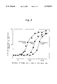
  • FIG. 3 is a graph showing a relating between the rate of decrease in the thickness of a liquid lubricant film and the distance between the outer edge of a magnetic disk and a side wall.
  • a magnetic disk drive embodying the present invention is shown and loaded with two magnetic disks 11 by way of example.
  • Each disk 11 has its surfaces covered with a film of PFPE or similar liquid lubricant 20.
  • the disks 11 are parallel to each other and spaced by a preselected distance 12.
  • the disk drive includes a casing 15 accommodating the disks 11.
  • a motor 21 is mounted on the outer periphery of the casing 15 in order to rotate a shaft or spindle 22 disposed in the casing 15.
  • Magnetic heads 16 each faces the opposite major surfaces of one of the disks 11 so as to read data thereoutof.
  • a head actuator 17 is constructed integrally with the heads 16.
  • the casing 15 is made up of a top wall or lid 24, a bottom wall or lid 25, and a side wall 26 connecting the top wall 24 and side wall 25.
  • the top wall 24 faces one or upper disk 11 at a preselected distance 23 while the bottom wall 25 faces the other or lower disk 11 at the preselected distance 23.
  • the circumferential edge of each disk 11 faces the inner surface of the side wall 26 at a preselected distance 19 over substantially one half or outer half 27 thereof.
  • the PFPE film 20 covering the surfaces of the each disk 11 is 3 nm thick.
  • the disks 11 and the heads 16 mounted on the head actuator 17 constitute the disk drive.
  • the distance 23 between the upper disk 11 and the inner surface of the top wall 24 or between the lower disk 11 and the inner surface of the bottom wall 25 was selected to be 1.00 mm, 2.00 mm or 3.00 mm.
  • the distance 12 between the disks 11 was selected to be 1.00 mm, 2.00 mm or 3.00 mm.
  • the distance 19 between the circumferential edge 27 of each disk 11 and the inner periphery of the side wall 26 was sequentially varied from 0.05 mm to 20.00 mm. Under these conditions, the motor 21 was energized to cause the spindle 22, i.e., disks 11 to spin in a direction 28 (counterclockwise in FIG. 2) at a rate of 5,400 rpm.
  • the thickness of the lubricant films 20 was measured.
  • a stream of air 18 flows counterclockwise, as viewed in FIG. 2, via the gap 19 between the edge 27 of each disk 11 and the inner surface of the side wall 26.
  • FIG. 3 plots the results of the above experiments. As FIG. 3 indicates, as the distance 19 between the edge 27 of each disk 11 and the side wall 26 decreases, the rate of decrease in the thickness of the lubricant film 20 decreases. The distance 19 allowing only the thickness of the lubricant 20 to decrease without being effected by the air stream 18 was found to be 1.00 mm, 0.50 mm or 0.10 mm when the distances 12 and 23 were 1.00 mm, 2.00 mm or 3.00 mm.
  • each disk 11 has a radius r, and that a stream of air 13 causes a shearing force ⁇ 0 to act on the lubricant film 20 in the radial direction at a part of the surface of the disk 11 corresponding to the radius r.
  • the shearing force ⁇ 0 is expressed as:
  • ⁇ denotes the angular velocity of the disk 11
  • ⁇ denotes the kinematic viscosity of air
  • ⁇ denotes the density of air.
  • the shearing force ⁇ causes the lubricant 20 to be scattered around.
  • the shearing force ⁇ 0 is also zero and minimizes the scattering of the lubricant 20.
  • the previously stated air stream 18 occurs in the direction of rotation of the disks 11.
  • the velocity distribution of air stream depends on the Reynolds' number R. Let the distance 12 between the disks 11 and the distance 19 and 23 be represented by d each. Then, the distance is expressed as:
  • the present invention provides a magnetic disk drive capable of minimizing the decrease in the thickness of a liquid lubricant film covering a magnetic disk and ascribable to the rotation of the disk.
  • the circumferential edge of the disk and the side wall of a casing are spaced from each other by 0.01 mm or less.
  • the distance between the surface of the disk and a wall facing it, e.g., between the surfaces of adjacent disks or between the surface of each disk and the inner surface of a top wall or that of a bottom wall forming the casing is selected to be 3.00 mm or less.

Landscapes

  • Magnetic Record Carriers (AREA)

Abstract

A magnetic disk drive using a magnetic disk covered with a film of liquid lubricant for obviating wear ascribable to the friction and contact of the magnetic disk with a magnetic head is disclosed. The circumferential edge of the disk and the side wall of a casing are spaced from each other by 0.01 mm or less. In addition, the distance between the surface of the disk and a wall facing it, e.g., between the surfaces of adjacent disks or between the surface of each disk and the inner surface of a top wall or that of a bottom wall forming the casing is selected to be 3.00 mm or less.

Description

BACKGROUND OF THE INVENTION
The present invention relates to a magnetic disk drive and, more particularly, to a magnetic disk drive of the type using a magnetic disk covered with a film of liquid lubricant for obviating wear ascribable to the friction and contact of the disk with a magnetic head.
A magnetic disk mounted on a magnetic disk drive as a recording medium has customarily been covered with a film of perfluoropolyether (PFPE) or similar liquid lubricant. The film of liquid lubricant protects the disk from wear ascribable to friction and contact of the disk with a magnetic head. It is a common practice to mount a stack of magnetic disks on a magnetic disk drive, as taught in, e.g., Japanese Patent Laid-Open Publication No. 61-9818. Such magnetic disks are mounted on a single spindle at a small spacing in order to increase the capacity of the disk drive.
The problem with the magnetic disks of the kind described is that the liquid lubricant is scattered around due to centrifugal force while the disks spin, reducing the thickness of the films. The decrease in the thickness of the films is accelerated by the shearing forces of air streams flowing on the surfaces of the disks. The decrease in the thickness of the films directly translates into the decrease in the lubricating effect expected to obviate the wear. As a result, the disks wear due to friction acting between them and magnetic heads and the contact of the former with the latter. This causes information stored in the disks to be lost.
SUMMARY OF THE INVENTION
It is therefore an object of the present invention to provide a magnetic disk drive capable of reducing air streams to flow on the surfaces of magnetic disks and causative of the scattering of a liquid lubricant, and having a highly reliable and high-density recording configuration.
In accordance with the present invention, in a magnetic disk drive using a magnetic disk covered with a film of liquid lubricant for obviating wear ascribable to friction and contact of the disk with a magnetic head, the inner surface of a side wall facing the circumferential edge of the disk and the circumferential edge are spaced from each other by 0.10 mm or less.
Also, in accordance with the present invention, a magnetic disk drive using a magnetic disk covered with a film of liquid lubricant for obviating wear ascribable to friction and contact of the disk with a magnetic head, disk drive includes a side wall facing the circumferential edge of the disk, and a wall facing the surface of the disk. The inner surface of the side wall and the circumferential edge of the disk are spaced from each other by 0.10 mm or less. The surface of the disk and the inner surface of the wall are spaced from each other by 3.00 mm or less.
BRIEF DESCRIPTION OF THE DRAWINGS
The above and other objects, features and advantages of the present invention will become apparent from the following detailed description taken with the accompanying drawings in which:
FIG. 1 is a vertical section showing a magnetic disk drive embodying the present invention;
FIG. 2 is a horizontal section of the illustrative embodiment; and
FIG. 3 is a graph showing a relating between the rate of decrease in the thickness of a liquid lubricant film and the distance between the outer edge of a magnetic disk and a side wall.
DESCRIPTION OF THE PREFERRED EMBODIMENT
Referring to FIGS. 1 and 2, a magnetic disk drive embodying the present invention is shown and loaded with two magnetic disks 11 by way of example. Each disk 11 has its surfaces covered with a film of PFPE or similar liquid lubricant 20. The disks 11 are parallel to each other and spaced by a preselected distance 12. The disk drive includes a casing 15 accommodating the disks 11. A motor 21 is mounted on the outer periphery of the casing 15 in order to rotate a shaft or spindle 22 disposed in the casing 15. Magnetic heads 16 each faces the opposite major surfaces of one of the disks 11 so as to read data thereoutof. A head actuator 17 is constructed integrally with the heads 16.
The casing 15 is made up of a top wall or lid 24, a bottom wall or lid 25, and a side wall 26 connecting the top wall 24 and side wall 25. The top wall 24 faces one or upper disk 11 at a preselected distance 23 while the bottom wall 25 faces the other or lower disk 11 at the preselected distance 23. As shown in FIG. 2, the circumferential edge of each disk 11 faces the inner surface of the side wall 26 at a preselected distance 19 over substantially one half or outer half 27 thereof.
In the illustrative embodiment, the PFPE film 20 covering the surfaces of the each disk 11 is 3 nm thick. The disks 11 and the heads 16 mounted on the head actuator 17 constitute the disk drive.
For experiments, the distance 23 between the upper disk 11 and the inner surface of the top wall 24 or between the lower disk 11 and the inner surface of the bottom wall 25 was selected to be 1.00 mm, 2.00 mm or 3.00 mm. Also, the distance 12 between the disks 11 was selected to be 1.00 mm, 2.00 mm or 3.00 mm. Further, the distance 19 between the circumferential edge 27 of each disk 11 and the inner periphery of the side wall 26 was sequentially varied from 0.05 mm to 20.00 mm. Under these conditions, the motor 21 was energized to cause the spindle 22, i.e., disks 11 to spin in a direction 28 (counterclockwise in FIG. 2) at a rate of 5,400 rpm. On the elapse of 2,000 hours, the thickness of the lubricant films 20 was measured. In this case, a stream of air 18 flows counterclockwise, as viewed in FIG. 2, via the gap 19 between the edge 27 of each disk 11 and the inner surface of the side wall 26.
FIG. 3 plots the results of the above experiments. As FIG. 3 indicates, as the distance 19 between the edge 27 of each disk 11 and the side wall 26 decreases, the rate of decrease in the thickness of the lubricant film 20 decreases. The distance 19 allowing only the thickness of the lubricant 20 to decrease without being effected by the air stream 18 was found to be 1.00 mm, 0.50 mm or 0.10 mm when the distances 12 and 23 were 1.00 mm, 2.00 mm or 3.00 mm.
Assume that each disk 11 has a radius r, and that a stream of air 13 causes a shearing force τ0 to act on the lubricant film 20 in the radial direction at a part of the surface of the disk 11 corresponding to the radius r. Then, the shearing force τ0 is expressed as:
τ0=(ω.sup.3/2 ρν.sup.1/2 r)/2             Eq. (1)
where ω denotes the angular velocity of the disk 11, ν denotes the kinematic viscosity of air, and ρ denotes the density of air. Assume that a stream of air 14 flowing between the inner surface of the top wall 24 and that of the bottom wall 25 has a velocity V. Then, a shearing force τ ascribable to a stream of air is the gradient of the velocity V relative to a distance Z in the direction of rotation (distance between the disks 11). Therefore, assuming that the lubricant film 20 has a viscosity η, then the shearing force τ at a position represented by Z=0 (i.e. on the surface of the lubricant 20) corresponds to the shearing force To and is produced by:
τ=ηδν/δZ                            Eq. (2)
When the velocity V of the air stream 14 is positive (flowing toward the circumferential edge of the disk 11), the shearing force τ causes the lubricant 20 to be scattered around. When the velocity V is zero, the shearing force τ0 is also zero and minimizes the scattering of the lubricant 20.
Air flows radially outward in the gap between each disk 11 and the wall facing it, e.g., between the disk 11 and the inner surface of the top wall 24 or that of the bottom wall 25 or at the edge 27 and surface of the disk 11. On the other hand, air flows radially inward at the intermediate between the disks 11 or at the inner surface of the top wall 24 or that of the bottom wall 25. Further, the previously stated air stream 18 occurs in the direction of rotation of the disks 11.
The velocity distribution of air stream depends on the Reynolds' number R. Let the distance 12 between the disks 11 and the distance 19 and 23 be represented by d each. Then, the distance is expressed as:
R=ωd.sup.2 /ν                                     Eq. (3)
Assuming that the angular velocity ω and kinematic viscosity ν are constant, then the velocity V sequentially approaches zero as the Reynolds' number R, i.e., distance d decreases, as shown in FIG. 3. This effect is multiplied as the distances 12 and 23 decrease.
In summary, it will be seen that the present invention provides a magnetic disk drive capable of minimizing the decrease in the thickness of a liquid lubricant film covering a magnetic disk and ascribable to the rotation of the disk. For this purpose, in the disk drive, the circumferential edge of the disk and the side wall of a casing are spaced from each other by 0.01 mm or less. In addition, the distance between the surface of the disk and a wall facing it, e.g., between the surfaces of adjacent disks or between the surface of each disk and the inner surface of a top wall or that of a bottom wall forming the casing is selected to be 3.00 mm or less.
Various modifications will become possible for those skilled in the art after receiving the teachings of the present disclosure without departing from the scope thereof.

Claims (10)

What is claimed is:
1. In a magnetic disk drive using a magnetic disk covered with a film of liquid lubricant for obviating wear ascribable to friction and contact of said magnetic disk with a magnetic head, an inner surface of a side wall facing a circumferential edge of said magnetic disk and said circumferential edge are spaced from each other by 0.10 mm or less wherein said film of liquid decreases in thickness as a function of the spacing between said side wall and said circumferential edge of said magnetic disk defined by a sharply increasing threshold value when a ratio of a decrease of thickness of the lubricant at which the air flow can be neglected is at least 1.8%.
2. A magnetic disk drive as claimed in claim 1 wherein said film of liquid lubricant decreases in thickness responsive to a flow of the liquid lubricant with negligible shearing ascribed to air flow and as a function of the space between said edge of said magnetic disk and the side wall.
3. A magnetic disk drive as claimed in claim 1 wherein a surface of said disk is separated from other neighboring surfaces by a distance of no more than 3 mm, said film of liquid lubricant decreases in thickness as a function of the space between said edge of said magnetic disk and the side wall with a characteristic, wherein the decrease is about:
1.00 mm when the space is 1.00 mm;
0.50 mm when the space is 2.00 mm;
0.10 mm when the space is 3.00 mm.
4. A magnetic disk drive using a magnetic disk covered with a film of liquid lubricant for obviating wear ascribable to friction and contact of said magnetic disk with a magnetic disk, said magnetic disk drive comrpsing:
a side wall facing a circumferential edge of said magnetic disk; and
a wall facing a surface of said magnetic disk;
wherein an inner surface of said side wall and said circumferential edge of said magnetic disk are spaced from each other by 0.10 mm or less, wherein said surface of said magnetic disk and an inner surface of said wall are spaced from each other by 3.00 mm or less, and wherein said film of liquid lubricant decreases in thickness as a function of the spacing between said side wall and said circumferential edge of said magnetic disk defined by a sharply increasing threshold value when a ratio of a decrease of thickness of the lubricant at which the air flow can be neglected is at least 1.8%.
5. A magnetic disk drive as claimed in claim 4, wherein said magnetic disk is mounted on a casing including said side wall and said wall and is spaced from adjacent magnetic disks by a preselected distance.
6. A magnetic disk drive as claimed in claim 5 wherein said film of liquid lubricant decreases in thickness responsive to a flow of the liquid lubricant with negligible shearing ascribed to air flow and as a function of the space between said edge of said magnetic disk and the side wall.
7. A magnetic disk drive as claimed in claim 5 wherein a surface of said disk is separated from other neighboring surfaces by a distance of no more than 3 mm, said film of liquid lubricant decreases in thickness as a function of the space between said edge of said magnetic disk and the side wall with a characteristic, wherein the decrease is about:
1.00 mm when the space is 1.00 mm;
0.50 mm when the space is 2.00 mm;
0.10 mm when the space is 3.00 mm.
8. In a magnetic disk drive using a magnetic disk covered with a film of liquid lubricant for obviating wear ascribable to friction and contact of said magnetic disk with a magnetic head, an inner surface of a side wall facing a circumferential edge of said magnetic disk and said circumferential edge are spaced from each other by 0.10 mm or less; wherein said disk is rotated at a speed which can scatter said liquid lubricant responsive to shearing forces τo generated by said rotation, wherein said film of liquid lubricant has a thickness decreasing in thickness as a function of a distance between said outer edge of the magnetic disk and the side wall, and minimizing said scattering by limiting said shearing forces expressed as τ0=(ω3/2 ρν1/2 r)/2 where: τo=shearing force; ω=angular velocity; ν=kinematic viscosity of air; ρ=density of air; said shear force to being limited by reducing a Reynolds number described as R=ωd2/ν by reducing d which is the distance between a circumference of the disk and said side wall to no more than 1 mm defined by a threshold value sharply increasing when a ratio of decrease of the lubricant exceeds 1.8%.
9. A magnetic disk drive comprising a magnetic disk covered with a film of liquid lubricant for obviating wear ascribable to friction and contact of said magnetic disk with a magnetic head, said magnetic disk drive comprising:
a side wall facing a circumferential edge of said magnetic disk;
a wall facing a surface of said magnetic disk;
wherein an inner surface of said side wall and said circumferential edge of said magnetic disk are spaced from each other by 0.10 mm or less, and wherein said surface of said magnetic disk and an inner surface of said wall are spaced from each other by 3.00 mm or less;
wherein said magnetic disk is mounted on a casing including said side wall and said wall and is spaced from adjacent magnetic disks by a preselected distance; and
wherein said disk is rotated at a speed which can scatter said liquid lubricant responsive to shearing forces τ generated by said rotation,
wherein said film of liquid lubricant has a thickness decreasing in thickness as a function of a distance between said outer edge of the magnetic disk and the side wall, and minimizing said scattering by limiting said shearing forces τo expressed as τ0=(ω3/2 ρν1/2 r)/2 where: τo=shearing force; ω=angular velocity; ν=kinematic viscosity of air; ρ=density of air; said shear force τo being limited by reducing a Reynolds number described as R=ωd2/ν by reducing d which is the distance between a circumference of the disk and said side wall to no more than 1 mm defined by a threshold value sharply increasing when a ratio of decrease of the lubricant exceeds 1.8%.
10. A magnetic disk drive using a magnetic disk covered with a film of liquid lubricant for obviating wear ascribable to friction and a contact of said magnetic disk with a magnetic head, said magnetic disk drive comprising:
a side wall facing a circumferential edge of said magnetic disk; and
a wall facing a surface of said magnetic disk;
wherein an inner surface of said side wall and said circumferential edge of said magnetic disk are spaced from each other by a first distance and wherein said surface of said magnetic disk and an inner surface of said wall are spaced from each other a second distance, and wherein said film of liquid lubricant decreases in thickness as a function of the first distance between said circumferential edge of said magnetic disk and said side wall defined by a threshold value sharply increasing when a ratio of decrease of thickness of the lubricant at which the air flow can be neglected is at least 1.8%.
US08/785,384 1996-01-26 1997-01-21 Magnetic disk drive Expired - Lifetime US6118617A (en)

Applications Claiming Priority (2)

Application Number Priority Date Filing Date Title
JP8-011467 1996-01-26
JP8011467A JP2760374B2 (en) 1996-01-26 1996-01-26 Magnetic disk drive

Publications (1)

Publication Number Publication Date
US6118617A true US6118617A (en) 2000-09-12

Family

ID=11778891

Family Applications (1)

Application Number Title Priority Date Filing Date
US08/785,384 Expired - Lifetime US6118617A (en) 1996-01-26 1997-01-21 Magnetic disk drive

Country Status (2)

Country Link
US (1) US6118617A (en)
JP (1) JP2760374B2 (en)

Cited By (1)

* Cited by examiner, † Cited by third party
Publication number Priority date Publication date Assignee Title
EP1523005A3 (en) * 2003-10-09 2006-11-29 Hitachi Global Storage Technologies B. V. Disk drive

Families Citing this family (1)

* Cited by examiner, † Cited by third party
Publication number Priority date Publication date Assignee Title
JP3732001B2 (en) 1998-02-13 2006-01-05 株式会社日立グローバルストレージテクノロジーズ Magnetic disk unit

Citations (4)

* Cited by examiner, † Cited by third party
Publication number Priority date Publication date Assignee Title
JPS619818A (en) * 1984-06-25 1986-01-17 Toshiba Corp Magnetic disk device
JPH02281496A (en) * 1989-04-21 1990-11-19 Nec Corp Magnetic disk device
US5381284A (en) * 1992-05-18 1995-01-10 International Business Machines Corporation Spacer ring reservoir for magnetic recording disk lubricant
US5631787A (en) * 1994-06-27 1997-05-20 Quantum Corporation Power reduction shroud for a hard disk drive

Patent Citations (4)

* Cited by examiner, † Cited by third party
Publication number Priority date Publication date Assignee Title
JPS619818A (en) * 1984-06-25 1986-01-17 Toshiba Corp Magnetic disk device
JPH02281496A (en) * 1989-04-21 1990-11-19 Nec Corp Magnetic disk device
US5381284A (en) * 1992-05-18 1995-01-10 International Business Machines Corporation Spacer ring reservoir for magnetic recording disk lubricant
US5631787A (en) * 1994-06-27 1997-05-20 Quantum Corporation Power reduction shroud for a hard disk drive

Cited By (1)

* Cited by examiner, † Cited by third party
Publication number Priority date Publication date Assignee Title
EP1523005A3 (en) * 2003-10-09 2006-11-29 Hitachi Global Storage Technologies B. V. Disk drive

Also Published As

Publication number Publication date
JPH09204767A (en) 1997-08-05
JP2760374B2 (en) 1998-05-28

Similar Documents

Publication Publication Date Title
US5533811A (en) Hydrodynamic bearing having inverted surface tension seals
US5189574A (en) Flexible information storing disk apparatus having laminar air flow
EP1336969B1 (en) Hard disk drive having air pumping groove
JP2867911B2 (en) Magnetic disk drive
US7281852B2 (en) Spool bearing with asymmetric sealing
US7102851B2 (en) Hydrodynamic bearing and disk recording/reproducing apparatus
JPS5936361A (en) rotating head assembly
US5485327A (en) Magnetic memory device having a perfluro-polyether film coated on an inner surface of its housing for entrapping dust
US6379047B1 (en) Fluid bearing apparatus
JPS6058548B2 (en) magnetic disk device
US5488521A (en) Information recording apparatus with a non-newtonian liquid bearing
JPH03150778A (en) Disk device
US7008110B2 (en) Hydrodynamic pivot bearing
US5997179A (en) Multifluid application in hydrodynamic fluid bearing to reduce evaporation and control stiffness and other bearing performance
JP2760374B2 (en) Magnetic disk drive
US5793567A (en) Spindle motor for disk drive
JPS60136980A (en) magnetic disk device
US6822825B2 (en) Stiffness compensation for a thermally compensated fluid dynamic bearing
US7002768B2 (en) Disk drive having reduced variation of disk surface lubricant layer thickness
US6466406B1 (en) Data-storage cartridge having one or more surface recesses for improved internal air circulation
JPH05266467A (en) Liquid lubricant application method for magnetic disk
JPH0281311A (en) Rotary head assembly of magnetic recording and reproducing device
JPH0529962B2 (en)
JPS59193570A (en) rotating head assembly
JPH07305719A (en) motor

Legal Events

Date Code Title Description
AS Assignment

Owner name: NEC CORPORATION, JAPAN

Free format text: ASSIGNMENT OF ASSIGNORS INTEREST;ASSIGNOR:YANAGISAWA, MASAHIRO;REEL/FRAME:008403/0722

Effective date: 19970117

FEPP Fee payment procedure

Free format text: PAYOR NUMBER ASSIGNED (ORIGINAL EVENT CODE: ASPN); ENTITY STATUS OF PATENT OWNER: LARGE ENTITY

FEPP Fee payment procedure

Free format text: PAYER NUMBER DE-ASSIGNED (ORIGINAL EVENT CODE: RMPN); ENTITY STATUS OF PATENT OWNER: LARGE ENTITY

Free format text: PAYOR NUMBER ASSIGNED (ORIGINAL EVENT CODE: ASPN); ENTITY STATUS OF PATENT OWNER: LARGE ENTITY

STCF Information on status: patent grant

Free format text: PATENTED CASE

AS Assignment

Owner name: TDK CORPORATION, JAPAN

Free format text: ASSIGNMENT OF ASSIGNORS INTEREST;ASSIGNOR:NEC CORPORATION;REEL/FRAME:014653/0526

Effective date: 20021227

FPAY Fee payment

Year of fee payment: 4

FPAY Fee payment

Year of fee payment: 8

FPAY Fee payment

Year of fee payment: 12