US6117586A - Cap assembly of battery - Google Patents
Cap assembly of battery Download PDFInfo
- Publication number
- US6117586A US6117586A US09/165,308 US16530898A US6117586A US 6117586 A US6117586 A US 6117586A US 16530898 A US16530898 A US 16530898A US 6117586 A US6117586 A US 6117586A
- Authority
- US
- United States
- Prior art keywords
- battery
- positive
- cap plate
- rivet
- cap
- Prior art date
- Legal status (The legal status is an assumption and is not a legal conclusion. Google has not performed a legal analysis and makes no representation as to the accuracy of the status listed.)
- Expired - Lifetime
Links
Images


Classifications
-
- H—ELECTRICITY
- H01—ELECTRIC ELEMENTS
- H01M—PROCESSES OR MEANS, e.g. BATTERIES, FOR THE DIRECT CONVERSION OF CHEMICAL ENERGY INTO ELECTRICAL ENERGY
- H01M50/00—Constructional details or processes of manufacture of the non-active parts of electrochemical cells other than fuel cells, e.g. hybrid cells
- H01M50/50—Current conducting connections for cells or batteries
- H01M50/572—Means for preventing undesired use or discharge
- H01M50/574—Devices or arrangements for the interruption of current
- H01M50/578—Devices or arrangements for the interruption of current in response to pressure
-
- H—ELECTRICITY
- H01—ELECTRIC ELEMENTS
- H01M—PROCESSES OR MEANS, e.g. BATTERIES, FOR THE DIRECT CONVERSION OF CHEMICAL ENERGY INTO ELECTRICAL ENERGY
- H01M50/00—Constructional details or processes of manufacture of the non-active parts of electrochemical cells other than fuel cells, e.g. hybrid cells
- H01M50/30—Arrangements for facilitating escape of gases
- H01M50/342—Non-re-sealable arrangements
- H01M50/3425—Non-re-sealable arrangements in the form of rupturable membranes or weakened parts, e.g. pierced with the aid of a sharp member
-
- H—ELECTRICITY
- H01—ELECTRIC ELEMENTS
- H01M—PROCESSES OR MEANS, e.g. BATTERIES, FOR THE DIRECT CONVERSION OF CHEMICAL ENERGY INTO ELECTRICAL ENERGY
- H01M10/00—Secondary cells; Manufacture thereof
- H01M10/05—Accumulators with non-aqueous electrolyte
- H01M10/052—Li-accumulators
- H01M10/0525—Rocking-chair batteries, i.e. batteries with lithium insertion or intercalation in both electrodes; Lithium-ion batteries
-
- H—ELECTRICITY
- H01—ELECTRIC ELEMENTS
- H01M—PROCESSES OR MEANS, e.g. BATTERIES, FOR THE DIRECT CONVERSION OF CHEMICAL ENERGY INTO ELECTRICAL ENERGY
- H01M50/00—Constructional details or processes of manufacture of the non-active parts of electrochemical cells other than fuel cells, e.g. hybrid cells
- H01M50/10—Primary casings; Jackets or wrappings
- H01M50/147—Lids or covers
- H01M50/148—Lids or covers characterised by their shape
- H01M50/15—Lids or covers characterised by their shape for prismatic or rectangular cells
-
- H—ELECTRICITY
- H01—ELECTRIC ELEMENTS
- H01M—PROCESSES OR MEANS, e.g. BATTERIES, FOR THE DIRECT CONVERSION OF CHEMICAL ENERGY INTO ELECTRICAL ENERGY
- H01M50/00—Constructional details or processes of manufacture of the non-active parts of electrochemical cells other than fuel cells, e.g. hybrid cells
- H01M50/50—Current conducting connections for cells or batteries
- H01M50/531—Electrode connections inside a battery casing
-
- H—ELECTRICITY
- H01—ELECTRIC ELEMENTS
- H01M—PROCESSES OR MEANS, e.g. BATTERIES, FOR THE DIRECT CONVERSION OF CHEMICAL ENERGY INTO ELECTRICAL ENERGY
- H01M50/00—Constructional details or processes of manufacture of the non-active parts of electrochemical cells other than fuel cells, e.g. hybrid cells
- H01M50/50—Current conducting connections for cells or batteries
- H01M50/543—Terminals
-
- H—ELECTRICITY
- H01—ELECTRIC ELEMENTS
- H01M—PROCESSES OR MEANS, e.g. BATTERIES, FOR THE DIRECT CONVERSION OF CHEMICAL ENERGY INTO ELECTRICAL ENERGY
- H01M50/00—Constructional details or processes of manufacture of the non-active parts of electrochemical cells other than fuel cells, e.g. hybrid cells
- H01M50/50—Current conducting connections for cells or batteries
- H01M50/572—Means for preventing undesired use or discharge
- H01M50/584—Means for preventing undesired use or discharge for preventing incorrect connections inside or outside the batteries
- H01M50/59—Means for preventing undesired use or discharge for preventing incorrect connections inside or outside the batteries characterised by the protection means
- H01M50/591—Covers
-
- H—ELECTRICITY
- H01—ELECTRIC ELEMENTS
- H01M—PROCESSES OR MEANS, e.g. BATTERIES, FOR THE DIRECT CONVERSION OF CHEMICAL ENERGY INTO ELECTRICAL ENERGY
- H01M2200/00—Safety devices for primary or secondary batteries
-
- H—ELECTRICITY
- H01—ELECTRIC ELEMENTS
- H01M—PROCESSES OR MEANS, e.g. BATTERIES, FOR THE DIRECT CONVERSION OF CHEMICAL ENERGY INTO ELECTRICAL ENERGY
- H01M2200/00—Safety devices for primary or secondary batteries
- H01M2200/20—Pressure-sensitive devices
-
- Y—GENERAL TAGGING OF NEW TECHNOLOGICAL DEVELOPMENTS; GENERAL TAGGING OF CROSS-SECTIONAL TECHNOLOGIES SPANNING OVER SEVERAL SECTIONS OF THE IPC; TECHNICAL SUBJECTS COVERED BY FORMER USPC CROSS-REFERENCE ART COLLECTIONS [XRACs] AND DIGESTS
- Y02—TECHNOLOGIES OR APPLICATIONS FOR MITIGATION OR ADAPTATION AGAINST CLIMATE CHANGE
- Y02E—REDUCTION OF GREENHOUSE GAS [GHG] EMISSIONS, RELATED TO ENERGY GENERATION, TRANSMISSION OR DISTRIBUTION
- Y02E60/00—Enabling technologies; Technologies with a potential or indirect contribution to GHG emissions mitigation
- Y02E60/10—Energy storage using batteries
Definitions
- the present invention relates to a battery, and more particularly, to a cap assembly of a battery having an improved structure which can be electrically disconnected from other parts when a safety member is ruptured due to the accidental internal pressure increase of the battery.
- a lithium secondary (i.e. rechargeable) battery has about 3 times the energy density per unit weight of conventional batteries such as a lead acid battery, a Ni-Cd battery, and a Ni-H battery, and can be fast charged.
- lithium cobalt oxide (LiCoO 2 ), lithium nickel oxide (LiNiO 2 ), lithium manganese oxide (LiMn 2 O 4 ) or the like is used as an active material of a positive electrode, and lithium, lithium alloys, a carbon material or the like is used as an active material of a negative electrode.
- organic electrolyte or solid polymer electrolyte is used as an electrolyte.
- the shape of a secondary battery is cylindrical or rectangular, and the rectangular shape is advantageous to making the portable appliances light and small.
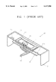
- a conventional lithium secondary battery of a rectangular shape comprises a battery case 17 for accommodating an electrode core (not shown) which is alternately laminated with positive electrode plates and negative electrode plates having separators therebetween, and a cap assembly 10 attached to the upper portion of the battery case 17.
- the cap assembly 10 includes a cap plate 12 for covering the upper portion of the battery case 17, a positive terminal 11 installed on the cap plate 12, and a rivet member 15 inserted through holes formed in the positive terminal 11 and the cap plate 12, for joining the positive terminal 11 to the cap plate 12.
- a first insulating member 13 is interposed between the positive terminal 11 and the cap plate 12, and the cap plate 12 and the rivet member 15 are insulated from each other by a second insulating member 14.
- a positive tap 16 which is connected to the positive electrode plates (not shown) is welded to the rivet member 15.
- the battery case 17 is connected to a negative tap (not shown).
- An electrolyte injection hole 12a for injecting an electrolyte into the battery case 17 is formed at one side of the cap plate 12, and a rupturing portion 12b is formed at the other side of the cap plate 12, to rupture when the internal pressure of the battery is abnormally high.
- the rupturing portion 12a of the cap plate 12 ruptures, and gas within the battery is exhausted. At this time, since the battery is still electrically connected, and has no electrical safety means, the portable appliance in which the battery is used may suffer a subsequent accident such as an electrical shock.
- a cap assembly of a battery comprising: a cap plate for covering the upper portion of a battery case; a positive terminal installed on the cap plate, insulated from the cap plate; a rivet member having a rivet protrusion, through which a vent hole is formed, inserted through holes formed in the cap plate and the positive terminal for riveting them together, the rivet member electrically connected to the positive terminal; a safety member installed at the lower end of rivet member, blocking the vent hole; and a positive tap fixing member attached to the lower end of the safety member and joined to a positive tap of an electrode assembly in the battery case, wherein the safety member is ruptured and separated from the positive tap fixing member by an internal pressure increase of the battery case.
- the safety member and the positive tap fixing member are joined to each other by welding.
- the safety member is preferably formed in the shape of a hemisphere.
- FIG. 1 is a cut away perspective view illustrating a cap assembly of a conventional lithium battery of a rectangular shape
- FIG. 2 is a exploded perspective view illustrating a cap assembly of a battery according to the present invention.
- FIG. 3 is a sectional view illustrating an assembled cap assembly of FIG. 2.
- FIG. 2 shows a secondary battery which employs a cap assembly according to the present invention.
- a battery case 23 accommodates an electrode core 22 which is laminated of alternating negative electrode plates 32 and positive electrode plates 33, having separators 31 therebetween.
- the positive electrode plates 33 and the negative electrode plates 32 are connected to a positive tap 22a and a negative tap 22c, respectively.
- the negative tap 22c is connected to the battery case 23.
- An insulating plate 24 is positioned on the electrode core 22, and the positive tap 22a projects through a hole formed in the insulating plate and is attached to a positive tap fixing member 48.
- a battery cap assembly 40 according to the present invention is installed on the battery case 23.
- the cap assembly 40 includes a cap plate 43 for covering the upper portion of the battery case 23, and a positive terminal 41 installed on the cap plate 43.
- a first insulating member 42 is interposed between the positive terminal 41 and the cap plate 43.
- a gasket 44 having an insulating function is attached to the lower surface of the cap plate 43.
- An electrolyte injection hole 43a is formed at the cap plate 43 for injecting an electrolyte containing a lithium salt into the battery case 23.
- the cap plate 43, the first insulating member 42, the positive terminal 41 and the gasket 44 are riveted together by a rivet member 46.
- a rivet protrusion 46b of the rivet member 46 is inserted through holes formed in the cap plate 43, the first insulating member 42, the positive terminal 41 and the gasket 44, for riveting them.
- a vent hole 46a is formed in the rivet protrusion 46b through the rivet member 46, and the vent hole 46a communicates with the inside of the battery case 23 when the battery has been assembled.
- the rivet member 46 is insulated from the cap plate 43 by a second insulating member 45 interposed therebetween.
- auxiliary metal members 49 may be attached to the sides of the second insulating member 45. That is, the auxiliary metal members 49 can be attached to the second insulating member 45 by a projection 49a formed on the auxiliary metal members 49 which fits into a slot 45a formed in the second insulating member 45.
- the auxiliary metal members 49 serve to securely fix the positive tap fixing member 48.
- a safety member 47 is installed at the lower end of rivet member 46 for blocking the vent hole 46a. It is preferable that the circumferential surface of the safety member 47 is welded to the lower end of the rivet member 46 at welding points W2 and W4.
- the safety member 47 is preferably formed in the shape of a hemisphere.
- the lowest point of the safety member 47 is welded to the positive tap fixing member 48 at a welding point W3.
- the positive tap fixing member 48 is welded to the auxiliary metal member 49 at welding points W1 and W5.
- a current flows from the electrode core 22 to the positive terminal 41 via the positive tap 22a, the positive tap fixing member 48, the safety member 47, and the rivet member 46, in sequence.
- the safety member 47 When the internal pressure of the battery rises, the safety member 47 is deformed by the high pressure, and is separated from the positive tap fixing member 48. Accordingly, the battery current can not flow. Then, the safety member 47 continues to deform toward the vent hole 46a of the rivet member 46 and finally ruptures. As a result, the inside of the battery case 23 communicates with the vent hole 46a, and the gas in the battery can be exhausted through the vent hole 46a. Therefore, the internal pressure is released.
- the cap assembly when a high internal pressure ruptures the safety member, the gas in the battery is exhausted, and simultaneously the current flow is blocked. Consequently, the battery is safer.
Landscapes
- Chemical & Material Sciences (AREA)
- Chemical Kinetics & Catalysis (AREA)
- Electrochemistry (AREA)
- General Chemical & Material Sciences (AREA)
- Engineering & Computer Science (AREA)
- Materials Engineering (AREA)
- Manufacturing & Machinery (AREA)
- Connection Of Batteries Or Terminals (AREA)
- Gas Exhaust Devices For Batteries (AREA)
- Secondary Cells (AREA)
Abstract
Description
Claims (5)
Applications Claiming Priority (2)
| Application Number | Priority Date | Filing Date | Title |
|---|---|---|---|
| KR97-52029 | 1997-10-10 | ||
| KR1019970052029A KR19990031352A (en) | 1997-10-10 | 1997-10-10 | Battery safety device |
Publications (1)
| Publication Number | Publication Date |
|---|---|
| US6117586A true US6117586A (en) | 2000-09-12 |
Family
ID=19522506
Family Applications (1)
| Application Number | Title | Priority Date | Filing Date |
|---|---|---|---|
| US09/165,308 Expired - Lifetime US6117586A (en) | 1997-10-10 | 1998-10-02 | Cap assembly of battery |
Country Status (7)
| Country | Link |
|---|---|
| US (1) | US6117586A (en) |
| JP (1) | JP4009019B2 (en) |
| KR (1) | KR19990031352A (en) |
| CN (1) | CN1127770C (en) |
| CA (1) | CA2249202C (en) |
| DE (1) | DE19846263C2 (en) |
| GB (1) | GB2330234B (en) |
Cited By (15)
| Publication number | Priority date | Publication date | Assignee | Title |
|---|---|---|---|---|
| US6284403B1 (en) * | 1997-12-18 | 2001-09-04 | Matsushita Electric Industrial Co., Ltd. | Closure assembly for sealed batteries |
| US6455193B1 (en) * | 1999-03-17 | 2002-09-24 | Sanyo Elelctric Co., Inc. | Sealed battery in which an electrolyte-injection hole is favorably sealed |
| US20020150813A1 (en) * | 1997-11-24 | 2002-10-17 | Un-Sick Park | Secondary battery |
| US20030059678A1 (en) * | 2001-09-24 | 2003-03-27 | Jung-Il Nam | Cap assembly and rectangular type secondary battery having the cap assembly |
| US20060057459A1 (en) * | 2004-09-09 | 2006-03-16 | Kwon Teak H | Can type secondary battery |
| WO2007097518A1 (en) * | 2006-02-23 | 2007-08-30 | Sk Energy Co., Ltd. | Safety apparatus using high power battery |
| US20090004559A1 (en) * | 2007-06-07 | 2009-01-01 | Gardner William H | Cap assembly for a high current capacity energy delivery device |
| US20090111016A1 (en) * | 2005-06-17 | 2009-04-30 | Junfeng Zhao | Cover Plate Assembly for Lithium Ion Battery, Battery Case and Battery Using the Same |
| US20140193703A1 (en) * | 2013-01-08 | 2014-07-10 | Robert Bosch Gmbh | Rechargeable battery |
| US9246153B2 (en) * | 2014-06-30 | 2016-01-26 | Samsung Sdi Co., Ltd. | Secondary battery |
| US9761860B2 (en) | 2014-01-30 | 2017-09-12 | Toyota Jidosha Kabushiki Kaisha | Secondary battery and method for producing secondary battery |
| US9761859B2 (en) | 2013-10-08 | 2017-09-12 | Samsung Sdi Co., Ltd. | Secondary battery |
| US10381630B2 (en) * | 2014-12-26 | 2019-08-13 | Gs Yuasa International Ltd. | Energy storage device |
| US20210234219A1 (en) * | 2019-04-09 | 2021-07-29 | Contemporary Amperex Technology Co., Limited | Top Cover Assembly of Secondary Battery and Secondary Battery |
| IT202200001847A1 (en) * | 2022-02-03 | 2023-08-03 | Gd Spa | Battery for energy storage |
Families Citing this family (12)
| Publication number | Priority date | Publication date | Assignee | Title |
|---|---|---|---|---|
| JP3756096B2 (en) * | 2001-10-02 | 2006-03-15 | Necトーキン栃木株式会社 | Sealed battery |
| KR100884793B1 (en) * | 2002-01-05 | 2009-02-23 | 삼성에스디아이 주식회사 | Safety valve and square type secondary battery provided with the same |
| KR100719728B1 (en) * | 2005-12-29 | 2007-05-17 | 삼성에스디아이 주식회사 | Cap Assembly and Secondary Battery Using the Same |
| JP5044933B2 (en) * | 2006-01-17 | 2012-10-10 | パナソニック株式会社 | battery |
| JP5147206B2 (en) * | 2006-08-11 | 2013-02-20 | 三洋電機株式会社 | Nonaqueous electrolyte secondary battery |
| JP5378366B2 (en) * | 2007-06-07 | 2013-12-25 | エー123 システムズ, インコーポレイテッド | Cap assembly for high current capacity energy supply equipment |
| US8236441B2 (en) * | 2007-07-24 | 2012-08-07 | A123 Systems, Inc. | Battery cell design and methods of its construction |
| US9236596B2 (en) * | 2011-06-30 | 2016-01-12 | Samsung Sdi Co., Ltd. | Rechargeable battery |
| JP5867376B2 (en) * | 2012-12-07 | 2016-02-24 | トヨタ自動車株式会社 | Sealed battery |
| JP6008200B2 (en) * | 2013-05-02 | 2016-10-19 | トヨタ自動車株式会社 | Secondary battery |
| KR102371193B1 (en) | 2015-08-10 | 2022-03-07 | 삼성에스디아이 주식회사 | Secondary Battery |
| JP6962168B2 (en) * | 2017-12-12 | 2021-11-05 | 三洋電機株式会社 | Square secondary battery and its manufacturing method |
Citations (11)
| Publication number | Priority date | Publication date | Assignee | Title |
|---|---|---|---|---|
| US3615868A (en) * | 1970-02-20 | 1971-10-26 | Illinois Tool Works | Battery cap assembly |
| US3915752A (en) * | 1974-05-08 | 1975-10-28 | Illinois Tool Works | Battery cap with flame barrier vent filter |
| US3992226A (en) * | 1975-07-25 | 1976-11-16 | Ultra-Mold Corporation | Anti-explosion cap for storage batteries |
| US4098963A (en) * | 1977-02-09 | 1978-07-04 | The Richardson Company | Vented battery cap |
| US4186247A (en) * | 1977-02-09 | 1980-01-29 | The Richardson Company | Vented battery cap |
| US4562127A (en) * | 1984-03-29 | 1985-12-31 | Domingo Mangone | Battery cap with electrolyte level indicator |
| US4978592A (en) * | 1988-09-20 | 1990-12-18 | Dattilo Donald P | Universal electrolyte level indicator for wet cell batteries |
| EP0689255A2 (en) * | 1994-05-23 | 1995-12-27 | Fuji Photo Film Co., Ltd. | Non-aqueous secondary cell |
| WO1996001504A1 (en) * | 1994-07-06 | 1996-01-18 | Elmer Hughett | Small battery cell |
| US5532075A (en) * | 1994-07-06 | 1996-07-02 | Alexander Manufacturing Corporation | Small battery cell |
| US5609972A (en) * | 1996-03-04 | 1997-03-11 | Polystor Corporation | Cell cap assembly having frangible tab disconnect mechanism |
Family Cites Families (1)
| Publication number | Priority date | Publication date | Assignee | Title |
|---|---|---|---|---|
| KR19990027311A (en) * | 1997-09-29 | 1999-04-15 | 손욱 | 켑 assembly of square battery |
-
1997
- 1997-10-10 KR KR1019970052029A patent/KR19990031352A/en not_active Ceased
-
1998
- 1998-09-18 JP JP26517698A patent/JP4009019B2/en not_active Expired - Lifetime
- 1998-09-28 GB GB9821057A patent/GB2330234B/en not_active Expired - Lifetime
- 1998-10-02 US US09/165,308 patent/US6117586A/en not_active Expired - Lifetime
- 1998-10-05 CA CA002249202A patent/CA2249202C/en not_active Expired - Fee Related
- 1998-10-07 DE DE19846263A patent/DE19846263C2/en not_active Expired - Fee Related
- 1998-10-10 CN CN98124137A patent/CN1127770C/en not_active Expired - Fee Related
Patent Citations (12)
| Publication number | Priority date | Publication date | Assignee | Title |
|---|---|---|---|---|
| US3615868A (en) * | 1970-02-20 | 1971-10-26 | Illinois Tool Works | Battery cap assembly |
| US3915752A (en) * | 1974-05-08 | 1975-10-28 | Illinois Tool Works | Battery cap with flame barrier vent filter |
| US3992226A (en) * | 1975-07-25 | 1976-11-16 | Ultra-Mold Corporation | Anti-explosion cap for storage batteries |
| US4098963A (en) * | 1977-02-09 | 1978-07-04 | The Richardson Company | Vented battery cap |
| US4186247A (en) * | 1977-02-09 | 1980-01-29 | The Richardson Company | Vented battery cap |
| US4562127A (en) * | 1984-03-29 | 1985-12-31 | Domingo Mangone | Battery cap with electrolyte level indicator |
| US4978592A (en) * | 1988-09-20 | 1990-12-18 | Dattilo Donald P | Universal electrolyte level indicator for wet cell batteries |
| EP0689255A2 (en) * | 1994-05-23 | 1995-12-27 | Fuji Photo Film Co., Ltd. | Non-aqueous secondary cell |
| WO1996001504A1 (en) * | 1994-07-06 | 1996-01-18 | Elmer Hughett | Small battery cell |
| US5532075A (en) * | 1994-07-06 | 1996-07-02 | Alexander Manufacturing Corporation | Small battery cell |
| US5588970A (en) * | 1994-07-06 | 1996-12-31 | Hughett; Elmer | Method for vacuum filling and sealing of a battery cell |
| US5609972A (en) * | 1996-03-04 | 1997-03-11 | Polystor Corporation | Cell cap assembly having frangible tab disconnect mechanism |
Cited By (23)
| Publication number | Priority date | Publication date | Assignee | Title |
|---|---|---|---|---|
| US20020150813A1 (en) * | 1997-11-24 | 2002-10-17 | Un-Sick Park | Secondary battery |
| US6284403B1 (en) * | 1997-12-18 | 2001-09-04 | Matsushita Electric Industrial Co., Ltd. | Closure assembly for sealed batteries |
| US6455193B1 (en) * | 1999-03-17 | 2002-09-24 | Sanyo Elelctric Co., Inc. | Sealed battery in which an electrolyte-injection hole is favorably sealed |
| US20030059678A1 (en) * | 2001-09-24 | 2003-03-27 | Jung-Il Nam | Cap assembly and rectangular type secondary battery having the cap assembly |
| US9040193B2 (en) * | 2001-09-24 | 2015-05-26 | Samsung Sdi Co., Ltd. | Cap assembly and rectangular type secondary battery having the cap assembly |
| US7939194B2 (en) * | 2004-09-09 | 2011-05-10 | Samsung Sdi Co., Ltd. | Can type secondary battery |
| US20060057459A1 (en) * | 2004-09-09 | 2006-03-16 | Kwon Teak H | Can type secondary battery |
| US20090111016A1 (en) * | 2005-06-17 | 2009-04-30 | Junfeng Zhao | Cover Plate Assembly for Lithium Ion Battery, Battery Case and Battery Using the Same |
| WO2007097518A1 (en) * | 2006-02-23 | 2007-08-30 | Sk Energy Co., Ltd. | Safety apparatus using high power battery |
| US20100233536A1 (en) * | 2006-02-23 | 2010-09-16 | Sk Energy Co., Ltd. | Safety apparatus using high power battery |
| CN101385162B (en) * | 2006-02-23 | 2010-11-10 | Sk能源株式会社 | Safety device for high-power battery |
| US8119280B2 (en) | 2007-06-07 | 2012-02-21 | A123 Systems, Inc. | Cap assembly for a high current capacity energy delivery device |
| US20090004559A1 (en) * | 2007-06-07 | 2009-01-01 | Gardner William H | Cap assembly for a high current capacity energy delivery device |
| US20140193703A1 (en) * | 2013-01-08 | 2014-07-10 | Robert Bosch Gmbh | Rechargeable battery |
| US10367185B2 (en) * | 2013-01-08 | 2019-07-30 | Samsung Sdi Co., Ltd. | Rechargeable battery |
| US9761859B2 (en) | 2013-10-08 | 2017-09-12 | Samsung Sdi Co., Ltd. | Secondary battery |
| US9761860B2 (en) | 2014-01-30 | 2017-09-12 | Toyota Jidosha Kabushiki Kaisha | Secondary battery and method for producing secondary battery |
| US9246153B2 (en) * | 2014-06-30 | 2016-01-26 | Samsung Sdi Co., Ltd. | Secondary battery |
| US10381630B2 (en) * | 2014-12-26 | 2019-08-13 | Gs Yuasa International Ltd. | Energy storage device |
| US20210234219A1 (en) * | 2019-04-09 | 2021-07-29 | Contemporary Amperex Technology Co., Limited | Top Cover Assembly of Secondary Battery and Secondary Battery |
| US12334570B2 (en) * | 2019-04-09 | 2025-06-17 | Contemporary Amperex Technology (Hong Kong) Limited | Top cover assembly of secondary battery and secondary battery |
| IT202200001847A1 (en) * | 2022-02-03 | 2023-08-03 | Gd Spa | Battery for energy storage |
| WO2023148549A1 (en) * | 2022-02-03 | 2023-08-10 | G.D S.P.A. | Battery for energy storage |
Also Published As
| Publication number | Publication date |
|---|---|
| JP4009019B2 (en) | 2007-11-14 |
| GB2330234A (en) | 1999-04-14 |
| CA2249202A1 (en) | 1999-04-10 |
| CN1127770C (en) | 2003-11-12 |
| JPH11162437A (en) | 1999-06-18 |
| DE19846263A1 (en) | 1999-04-29 |
| KR19990031352A (en) | 1999-05-06 |
| GB2330234B (en) | 1999-12-08 |
| GB9821057D0 (en) | 1998-11-18 |
| CA2249202C (en) | 2000-12-12 |
| CN1214553A (en) | 1999-04-21 |
| DE19846263C2 (en) | 2001-02-15 |
Similar Documents
| Publication | Publication Date | Title |
|---|---|---|
| US6117586A (en) | Cap assembly of battery | |
| EP3518305B1 (en) | Secondary battery | |
| JP2006128120A (en) | Lithium secondary battery | |
| JP2008140773A (en) | Battery module | |
| KR20110125488A (en) | Battery pack | |
| KR101483700B1 (en) | Secondary battery and battery pack including the same | |
| KR101121205B1 (en) | Secondary battery | |
| KR102335696B1 (en) | The Current Interrupt Device And The Cap Assembly | |
| KR101453783B1 (en) | Cap assembly and secondary battery using the same | |
| US7754376B2 (en) | Cylindrical lithium secondary battery and method of fabricating the same | |
| KR100696784B1 (en) | Cylindrical Lithium Secondary Battery and Manufacturing Method Thereof | |
| KR100889767B1 (en) | Lithium secondary battery having protection plate | |
| KR100601499B1 (en) | Cylindrical lithium secondary battery | |
| KR100646504B1 (en) | Cylindrical lithium secondary battery | |
| KR100601542B1 (en) | Cylindrical lithium ion secondary battery | |
| JP2006156362A (en) | Cylindrical lithium secondary battery | |
| KR20060037832A (en) | Secondary battery | |
| KR100457627B1 (en) | Secondary battery with non-weldindg type bottom plate | |
| KR100770098B1 (en) | Secondary battery | |
| KR100686811B1 (en) | Cylindrical lithium secondary battery | |
| KR20060059708A (en) | Cylindrical lithium secondary battery | |
| KR100561309B1 (en) | Cylindrical lithium secondary battery | |
| KR100686833B1 (en) | Secondary battery | |
| KR20060112732A (en) | Secondary Battery and Pack Battery Using the Same | |
| KR101275788B1 (en) | Battery module |
Legal Events
| Date | Code | Title | Description |
|---|---|---|---|
| AS | Assignment |
Owner name: SAMSUNG DISPLAY DEVICES, LTD., KOREA, REPUBLIC OF Free format text: ASSIGNMENT OF ASSIGNORS INTEREST;ASSIGNORS:KIM, CHANG-SEOB;KIM, HYUN-WOO;JANG, KI-WOONG;AND OTHERS;REEL/FRAME:009512/0471 Effective date: 19980902 |
|
| AS | Assignment |
Owner name: SAMSUNG DISPLAY DEVICES CO., LTD., KOREA, REPUBLIC Free format text: ASSIGNMENT OF ASSIGNORS INTEREST;ASSIGNORS:KIM, CHANG-SEOB;KIM, HYUN-WOO;JANG, KI-WOONG;AND OTHERS;REEL/FRAME:010004/0181;SIGNING DATES FROM 19990422 TO 19990427 |
|
| STCF | Information on status: patent grant |
Free format text: PATENTED CASE |
|
| FEPP | Fee payment procedure |
Free format text: PAYOR NUMBER ASSIGNED (ORIGINAL EVENT CODE: ASPN); ENTITY STATUS OF PATENT OWNER: LARGE ENTITY |
|
| FPAY | Fee payment |
Year of fee payment: 4 |
|
| FPAY | Fee payment |
Year of fee payment: 8 |
|
| FEPP | Fee payment procedure |
Free format text: PAYER NUMBER DE-ASSIGNED (ORIGINAL EVENT CODE: RMPN); ENTITY STATUS OF PATENT OWNER: LARGE ENTITY Free format text: PAYOR NUMBER ASSIGNED (ORIGINAL EVENT CODE: ASPN); ENTITY STATUS OF PATENT OWNER: LARGE ENTITY |
|
| FPAY | Fee payment |
Year of fee payment: 12 |