US6105828A - Non-bubble forming dropper tip - Google Patents
Non-bubble forming dropper tip Download PDFInfo
- Publication number
- US6105828A US6105828A US09/064,331 US6433198A US6105828A US 6105828 A US6105828 A US 6105828A US 6433198 A US6433198 A US 6433198A US 6105828 A US6105828 A US 6105828A
- Authority
- US
- United States
- Prior art keywords
- wall portion
- wall
- dropper tip
- fluid
- container
- Prior art date
- Legal status (The legal status is an assumption and is not a legal conclusion. Google has not performed a legal analysis and makes no representation as to the accuracy of the status listed.)
- Expired - Lifetime
Links
Images


Classifications
-
- A—HUMAN NECESSITIES
- A61—MEDICAL OR VETERINARY SCIENCE; HYGIENE
- A61F—FILTERS IMPLANTABLE INTO BLOOD VESSELS; PROSTHESES; DEVICES PROVIDING PATENCY TO, OR PREVENTING COLLAPSING OF, TUBULAR STRUCTURES OF THE BODY, e.g. STENTS; ORTHOPAEDIC, NURSING OR CONTRACEPTIVE DEVICES; FOMENTATION; TREATMENT OR PROTECTION OF EYES OR EARS; BANDAGES, DRESSINGS OR ABSORBENT PADS; FIRST-AID KITS
- A61F9/00—Methods or devices for treatment of the eyes; Devices for putting in contact-lenses; Devices to correct squinting; Apparatus to guide the blind; Protective devices for the eyes, carried on the body or in the hand
- A61F9/0008—Introducing ophthalmic products into the ocular cavity or retaining products therein
-
- B—PERFORMING OPERATIONS; TRANSPORTING
- B65—CONVEYING; PACKING; STORING; HANDLING THIN OR FILAMENTARY MATERIAL
- B65D—CONTAINERS FOR STORAGE OR TRANSPORT OF ARTICLES OR MATERIALS, e.g. BAGS, BARRELS, BOTTLES, BOXES, CANS, CARTONS, CRATES, DRUMS, JARS, TANKS, HOPPERS, FORWARDING CONTAINERS; ACCESSORIES, CLOSURES, OR FITTINGS THEREFOR; PACKAGING ELEMENTS; PACKAGES
- B65D47/00—Closures with filling and discharging, or with discharging, devices
- B65D47/04—Closures with discharging devices other than pumps
- B65D47/06—Closures with discharging devices other than pumps with pouring spouts or tubes; with discharge nozzles or passages
- B65D47/18—Closures with discharging devices other than pumps with pouring spouts or tubes; with discharge nozzles or passages for discharging drops; Droppers
Definitions
- This invention is generally directed to a novel non-bubble forming dropper tip which is used to dispense fluids, such as medications and the like. More particularly, the invention contemplates a novel multiple-use dropper tip which is designed to control air bubble development and drop size when the occasional bubble is encountered while dispensing viscous, low density, often thixotropic fluids, such as liquid eye medications or the like.
- FIGS. 6A-6Q A depiction of dispensing drops from a prior art dropper tip 20 is shown in FIGS. 6A-6Q.
- the dropper tip 20 is formed from a body 22 having an inner wall 24 which defines a conduit therethrough.
- the conduit is formed from a first cylindrical wall portion 26, which is connected to a larger diameter second cylindrical wall portion 28, which is connected to an even larger diameter third cylindrical wall portion 30.
- the transition between the first and second wall portions 26, 28 is not smooth and a sharp shoulder 32 is provided.
- the transition between the second and third wall portions 28, 30 is not smooth and a sharp shoulder 34 is provided.
- Bubble generation most often occurs during the aspiration phase of dispensing when the make-up air drives fluid back down the dropper tip 20 into the container 36.
- air returning quickly back down the conduit and encountering the sharp shoulders 32, 34 of the smaller-to-larger diameter transitions can cause bubbles to be formed if a film bridges across this transition edge resulting in a film covered aperture upon which the inrushing air will cause bubbles to be blown.
- Bubbles must be kept from blocking outward fluid flow paths where the bubbles can become entrained in the fluid and impair accurate drop formation.
- a second prior art dropper tip 38 is shown in FIG. 7.
- This dropper tip 38 is formed from a body 40 having an inner wall 42 which defines a conduit therethrough.
- the conduit is straight and has a small diameter.
- Conduit diameter is also important in controlling bubbles.
- a conduit which has a diameter that is too small will exhibit jetting and bubbling aspiration as shown in the prior art dropper tip 38 shown in FIG. 7
- the delivery tip surface 44 is rounded.
- the rounded surface 44 encourages the attachment of fluid thereto which can interfere with proper drop size, see FIGS. 6A-6Q.
- the present invention provides a novel dropper tip structure which overcomes these problems and presents other features and advantages over the prior art which will become apparent upon a reading of the attached specification, in combination with an examination of the drawings.
- a general object of the present invention is to provide a novel multiple-use dropper tip which is designed to control air bubble development and drop size when the occasional bubble is encountered while dispensing viscous, low density, often thixotropic fluids, such as liquid eye medications or the like.
- An object of the present invention is to provide a novel dropper tip having a delivery tip which controls drop size to promote limited momentary attachment of fluid thereto when fluid is being dispensed from the dropper tip.
- Another object of the present invention is to provide a novel dropper tip having a delivery tip which discourages fluid wetting and migration beyond the designated perimeter of the delivery tip.
- Yet another object of the present invention is to provide a novel dropper tip having an inner wall which discourages fluid wetting thereof.
- a further object of the present invention is to provide a novel dropper tip having an inner wall defining a conduit which is designed to encourage fluid detachment from the inner wall whenever the fluid is caused to flow away from the delivery tip back toward the container, such as after drops have been dispensed and the squeezed container has been released to aspirate make-up air.
- Yet a further object of the present invention is to provide a novel closure cap for sealing the dropper tip of the present invention.
- the present invention discloses a multiple-use dropper tip which is designed to control air bubble development and drop size when bubbles are encountered while dispensing fluids, such as liquid eye medications or the like.
- the dropper tip is connected to a squeezable container having the fluid therein and is used to dispense the fluid therefrom in a controlled manner.
- the dropper tip is formed from a body having first and second opposite ends and an inner wall defining a conduit therethrough.
- the inner wall smoothly diverges and gradually increases in inner diameter from the first end to the second end such that air bubbles are prevented from being trapped along the inner wall. That is to say, the inner wall defining the conduit does not have any sharp corners or steps therein upon which fluid could bridge and form bubbles.
- the body inner wall is highly polished and may be made of olefinic material, silicone rubber material, or fluorocarbons, including, but not limited to, polytetrafluoroethylene (PTFE), carbon tetrafluoroethylene (CTFE), fluoroethylene propylene (FEP) or the like, to resist fluid wetting, facilitate fluid detachment therefrom and to reduce fluid film thickness therealong.
- PTFE polytetrafluoroethylene
- CTFE carbon tetrafluoroethylene
- FEP fluoroethylene propylene
- the surface of the inner wall is smoothed to minimize surface roughness.
- a tubular portion having a flat end is provided at the first end of the body to promote limited momentary attachment of fluid thereto when fluid is being dispensed from the dropper tip.
- a sharp outer perimeter edge is provided by the flat end to provide an instant transition to discourage fluid wetting and migration beyond the designated perimeter of the flat end.
- a novel closure cap is provided for sealing the dropper tip of the present invention.
- the closure cap seals the dropper tip at two places to prevent the entrance of contaminants therein.
- FIG. 1 is a side elevational view of a novel dropper tip which incorporates the features of the present invention
- FIG. 2 is a cross-sectional view of the dropper tip shown in FIG. 1 attached to a container which is shown partially in cross-section;
- FIG. 3 is a top elevational view of the dropper tip shown in FIG. 1;
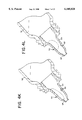
- FIGS. 4A-4G are cross-sectional views of the dropper tip shown in FIG. 1 attached to a container, which is shown partially in cross-section, showing a first drop formation and release;
- FIGS. 4H-4J are cross-sectional views of the dropper tip shown in FIG. 1 attached to a container, which is shown partially in cross-section, showing a first aspiration and bubble "parking";
- FIGS. 4K and 4L are cross-sectional views of the dropper tip shown in FIG. 1 attached to a container, which is shown partially in cross-section, showing the bubble at rest;
- FIGS. 4M-4P are cross-sectional views of the dropper tip shown in FIG. 1 attached to a container, which is shown partially in cross-section, a second drop formation and release;
- FIGS. 4Q and 4R are cross-sectional views of the dropper tip shown in FIG. 1 attached to a container, which is shown partially in cross-section, showing a second aspiration;
- FIGS. 4S and 4T are cross-sectional views of the dropper tip shown in FIG. 1 attached to a container, which is shown partially in cross-section, showing the bubbles at rest with successive bubbles joining together to form a single bubble;
- FIGS. 4U-4W are cross-sectional views of the dropper tip shown in FIG. 1 attached to a container, which is shown partially in cross-section, showing a large bubble migration into the container;
- FIG. 5 is a cross-sectional view of a novel closure cap secured to the container to which the novel dropper tip shown in FIG. 1 is attached;
- FIGS. 6A-6F are cross-sectional views of a prior art dropper tip attached to a container, which is shown partially in cross-section, showing a first drop formation and release;
- FIGS. 6G-6H are cross-sectional views of the prior art dropper tip attached to a container, which is shown partially in cross-section, showing a first aspiration and air trapping;
- FIG. 6I is a cross-sectional view of the prior art dropper tip attached to a container, which is shown partially in cross-section, showing the bubbles at rest;
- FIGS. 6J-6M are cross-sectional views of the prior art dropper tip attached to a container, which is shown partially in cross-section, showing a second drop formation with attached bubble due to trapped air;
- FIGS. 6N and 6O are cross-sectional views of the prior art dropper tip attached to a container, which is shown partially in cross-section, showing a second aspiration and air trapping;
- FIGS. 6P and 6Q are cross-sectional views of the prior art dropper tip attached to a container, which is shown partially in cross-section, showing a small bubble release into the container;
- FIG. 7 is a cross-sectional view of another prior art dropper tip attached to a container, which is shown partially in cross-section, showing an aspiration and bubble formation of a small inner diameter conduit.
- the present invention provides a multiple-use dropper tip 50 which is designed to control air bubble development and drop size when the occasional bubble is encountered while dispensing viscous, low density, often thixotropic fluids, such as liquid eye medications or the like.
- the dropper tip 50 is connected to a conventional squeezable plastic container 52 having the fluid therein and is used to dispense the fluid therefrom.
- the squeezable plastic container 52 is formed from a body 53 having an open mouth 55 and an opposite closed end (not shown). Threads 57 are provided proximate to the mouth 55 of the container 52 on the exterior of the body 53.
- the dropper tip 50 is formed from a body 54 having first and second opposite ends 56, 58 and an inner wall 60 defining a conduit therethrough.
- the inner wall 60 provided through the body 54 smoothly diverges and gradually increases in inner diameter from the first end 56 to the second end 58 such that air bubbles are prevented from being trapped along the inner wall 60. Because of this novel structure, sharp corners, sharp edges or pockets along the length of the inner wall 60 on which air bubbles could catch as can occur in the prior art, are eliminated in the present invention. In addition, the elimination of sharp corners, edges and pockets along the inner wall 60 help prevent the break-up of large bubbles into smaller ones and this elimination does not leave a place for bubbles to attach and re-enter the fluid flow during the next dispensing.
- the exterior surface of the body 54 generally follows the shape of the inner wall 60.
- Structure 62 is provided at the second end 58 of the body 54 along the exterior thereof for releasably attaching the body 54 within the open mouth 55 of the container 52.
- a circular shoulder 59 is provided on the exterior of the body 54 at a predetermined distance from the second end 58 of the body 54 and proximate to the structure 62 for reasons described herein.
- a tubular delivery tip 64 having a flat end surface 66 is provided at the first end 56 of the body 54.
- the flat end surface 66 of the delivery tip 64 controls drop size by providing an end flat of finite frontal area to promote limited momentary attachment of fluid thereto when fluid is being dispensed from the novel dropper tip 50 of the present invention.
- the tubular delivery tip 64 defines a cylindrical wall portion 68 of the inner wall 60. As shown in the drawings, the wall portion 68 is generally cylindrical, however, it is to be understood that the wall portion 68 may gradually diverge from its first end to its second end.
- the outer perimeter of the flat end surface 66 provides a sharp perimeter edge 70 to provide an instant transition to discourage fluid wetting and migration beyond the designated perimeter of the flat end surface 66.
- the delivery tip 64 is supplied by means of the internal conduit formed by the inner wall 60 which conducts fluid, such as medication, from the interior of the affixed squeezable container 52 to the delivery tip flat end surface 66.
- the inner wall 60 is designed and manufactured in a manner to discourage fluid wetting thereof.
- the inner wall 66 is designed to encourage fluid detachment therefrom whenever the fluid is caused to flow away from the delivery tip 64 back toward the container 52, such as after drops have been dispensed and the squeezed container 52 has been released to aspirate make-up air.
- the inner wall 60 further includes a first wall portion 72 having first and second opposite ends, a second wall portion 74 having first and second opposite ends, a third wall portion 76 having first and second opposite ends, and a fourth wall portion 78 having first and second opposite ends.
- the first end of the first wall portion 72 smoothly transitions with the second end of the cylindrical wall portion 68.
- the second end of the first wall portion 72 smoothly transitions with the first end of the second wall portion 74.
- the second end of the second wall portion 74 smoothly transitions with the first end of the third wall portion 76.
- the second end of the third wall portion 76 smoothly transitions with the first end of the fourth wall portion 78.
- the transition walls 72, 76 between the respective wall sections 68, 74, 78 are curved or arcuate and devoid of sharp corners.
- the first wall portion 72 is radiused to provide a smooth transition from the second end of the cylindrical wall portion 68 to the first end of the second wall portion 74.
- the inner diameter of the first wall portion 72 at its first end is equal to the inner diameter of the cylindrical wall portion 68 at its second end.
- the inner diameter of the first wall portion 72 at its first end is smaller than at its second end.
- the second wall portion 74 gradually diverges from its first end to its second end such that the inner diameter at its second end is greater than the inner diameter at its first end.
- the inner diameter of the second wall portion 74 at its first end is equal to the inner diameter of the first wall portion 72 at its second end.
- the third wall portion 76 is radiused to provide a smooth transition from the second end of the second wall portion 74 to the first end of the fourth wall portion 78.
- the inner diameter of the third wall portion 76 at its first end is equal to the inner diameter of the second wall portion 74 at its second end.
- the inner diameter of the third wall portion 76 at its first end is smaller than at its second end.
- the fourth wall portion 78 gradually diverges from its first end to its second end such that the inner diameter at its second end is greater than the inner diameter at its first end.
- the inner diameter of the fourth wall portion 78 at its first end is equal to the inner diameter of the third wall portion 76 at its second end.
- Bubble generation most often occurs during the aspiration phase of dispensing when the make-up air is sucked or drawn back into the container 52, as the wall of the container 52 is released and its inherent resiliency causes it to expand back to its original form or shape. When aspiration occurs, it tends to drive fluid back down the dropper tip 50 into the container 52. As is shown in the prior art in FIGS. 6A-6Q, air returning quickly back down the conduit and encountering sharp back side edges of any smaller-to-larger inner diameter transitions can cause bubbles to be formed if a film bridges across this transition edge resulting in a film covered aperture upon which the inrushing air will cause bubbles to be blown.
- the dropper tip 50 of the present invention incorporates several structural features to reduce incidences of film forming.
- the generously radiused wall portions 72, 76 reduce incidences of film forming.
- the surface of the inner wall 60 may be highly polished and/or may be materially resistant to wetting by the fluid to improve detachment of fluid from the inner wall 60 and/or minimize impeding of the fluids retreat as incoming air forces fluid back into the container 52 during aspiration.
- the resultant ease of flow prevents or minimizes fluid thickness along the inner wall 60 which, in turn, inhibits bridge conditions which could lead to film bridging across the conduit.
- the provision of highly polished surfaces and/or use of surface materials resist fluid wetting, facilitate fluid detachment and reduce fluid film thickness along the inner wall 60.
- an inner wall surface of highly polished (S.P.I.-S.P.E. #1 mirror finish) olefinic material such as DUPONT Grade 20 high density polyethylene (HDPE) or HUNTSMAN Grade 13R9A polypropylene (PP), or silicone rubber material, such as NuSIL Grade 4980 silicone rubber, provide a good passageway to resist bubble formation.
- olefinic material such as DUPONT Grade 20 high density polyethylene (HDPE) or HUNTSMAN Grade 13R9A polypropylene (PP), or silicone rubber material, such as NuSIL Grade 4980 silicone rubber
- a finely polished surface has less net surface area than a rougher finish.
- a fine surface finish also offers much shallower irregularities (but potentially many more on a microscopic level). These minute irregularities can trap air which suspends fluid and further reduces its contact with the surface.
- a rough surface can serve to place more surface area in contact, thereby allowing a film of fluid to puddle, cling, trap and resist flowing off.
- Surface roughness regardless of material choice, may have the effect of providing microscopic shelves on which fluid can cling, thereby increasing the overall depth of fluid flow washing the inner wall, inhibiting detachment and slowing the return of the flow during aspiration.
- the surface of the inner wall 60 is made as smooth as possible in order to optimize resistance to bubble formation by minimizing the volume of fluid available to close behind the inrushing make-up air.
- the mold on which the dropper tip 50 is formed is polished to a mirror finish to make the surface of the inner wall 60 smooth when the body 54 is molded out of the chosen material.
- TEFLON® polytetrafluoroethylene (PTFE), carbon tetrafluoroethylene (CTFE), fluoroethylene propylene (FEP) or the like
- TEFLON® polytetrafluoroethylene (PTFE), carbon tetrafluoroethylene (CTFE), fluoroethylene propylene (FEP) or the like
- TEFLON® polytetrafluoroethylene (PTFE), carbon tetrafluoroethylene (CTFE), fluoroethylene propylene (FEP) or the like
- FEP fluoroethylene propylene
- PE critical surface tension of 31 dynes/cm
- PTFE critical surface tension of 18 dynes/cm
- FEP critical surface tension of 16 dynes/cm
- the diverging inner wall 60 cross-section assists the non-wetting process by providing space separation between opposing points on the inner wall 60 and by causing the downwashing surface fluid to spread and thin over a constantly increasing circumferential surface.
- the size of the conduit is also important in controlling bubbles. As is shown in the prior art in FIG. 7, a conduit which is too small will exhibit jetting and bubbling aspiration.
- the conduit defined by the inner wall 60 of the present invention which has larger passages having generously radiused wall portions 72, 76, is very smooth and has divergent walls 74, 78, reduces or eliminates adverse impacts of bubble formation.
- the dropper tip 50 of the present invention provides a safe place to "park" the inevitable bubble such that the bubble will not re-enter into outward flow during dispensing as is shown in the extreme example in FIGS. 4A-4W.
- FIGS. 4Q-4T because the body 54 has at least one enlarged diameter wall portion, an air bubble can momentarily become entrained in the fluid, but the novel shape of the conduit 60 prevents permanent occlusion of the air bubble within the dispensed fluid, see FIGS. 4U-4W.
- an air bubble can momentarily occlude the conduit passageway, but the novel shape of the conduit 60 prevents permanent occlusion of the conduit passageway.
- FIG. 5 shows a novel closure cap 80 for sealing the dropper tip 50.
- a description of this novel closure cap 80 is provided, a description of how a prior art closure cap (not shown) would attach to the dropper tip 50 of the present invention is provided, along with the disadvantages created when a prior art closure cap is used with the novel dropper tip 50 of the present invention.
- Prior art closure caps provide two seals for sealing a dropper tip.
- the closure cap When a prior art closure cap is provided on the novel dropper tip 50 of the present invention, the closure cap bears on the flat end surface 66 of the delivery tip 64 to form a first seal for preventing accumulation of liquid within the closure cap and the closure cap bears on the top of the dropper tip circular shoulder 57 to form a second seal for preventing contaminants from entering into the dropper tip 50 and to seal the dropper tip 50 to the container 52.
- the Applicant has found that a problem arises when such a prior art closure cap is used on the dropper tip 50 of the present invention.
- the cylindrical delivery tip 64 will deform as a result of the compression applied by the prior art closure cap to perfect the first seal. This causes the wall of the cylindrical delivery tip 64 to diverge outwardly and deform. This obviously is not desirable.
- the novel closure cap 80 shown in FIG. 5 was developed to overcome this problem created by the prior art closure cap.
- the closure cap 80 is formed from a body 82 which includes a wall 84 which diverges outwardly from its first end to its second end.
- An end wall 86 closes the first end of the wall 84 and is angled relative to the wall 84.
- a circular wall 88 extends outwardly from the second end of the wall 84 and is angled relative to the wall 84. Walls 86 and 88 are parallel to each other.
- a depending circular skirt wall 90 extends from the outermost end of the wall 88 and is approximately perpendicular thereto.
- a circular shoulder 92 is formed between end wall 86 and outwardly diverging wall 84.
- the shoulder 92 has a curved surface 94 at its innermost point.
- a recess 96 is formed within the walls 84, 86, 88, 90 with one end of the recess 96 being closed by end wall 86 and the other end of the recess 96 being open.
- the area of the recess 96 between the shoulder 92 and end wall 86 is defined as a cap pocket.
- a plurality of threads 98 are provided on the interior of the wall 90 for mating with threads 57 on the container 52.
- the end wall 86 bears against the end flat 66 of the delivery tip 64.
- the delivery tip 64 seats within the cap pocket.
- the curved surface 94 bears against the curved exterior surface 100 of the body 54 proximate to the first wall portion 72.
- the interior of wall 88 bears against the top surface of the shoulder 59.
- the threads 98 are engaged with the threads 57 on the container 52.
- the bearing of the curved surface 94 against the curved exterior surface 100 of the body 54 proximate to the first wall portion 72 forms the primary seal for preventing accumulation of liquid within the closure cap 80 and places the main compression load on the dropper tip 50 radius, instead of on the cylindrical delivery tip 64 as occurs with the prior art closure cap.
- the cylindrical delivery tip 64 of the dropper tip 50 is lightly crushed (0.002"-0.005") within the cap pocket enough to seal against the end wall 86 inner surface, but not deform the cylindrical delivery tip 64.
- the bearing of the interior of the wall 88 against the top surface of the shoulder 59 forms the secondary seal for preventing contaminants from entering into the dropper tip 50 and to seal the dropper tip 50 to the container 52.
Landscapes
- Health & Medical Sciences (AREA)
- Engineering & Computer Science (AREA)
- Life Sciences & Earth Sciences (AREA)
- Biomedical Technology (AREA)
- Heart & Thoracic Surgery (AREA)
- Vascular Medicine (AREA)
- Ophthalmology & Optometry (AREA)
- Animal Behavior & Ethology (AREA)
- General Health & Medical Sciences (AREA)
- Public Health (AREA)
- Veterinary Medicine (AREA)
- Mechanical Engineering (AREA)
- Closures For Containers (AREA)
Abstract
Description
______________________________________
       PTFE         18 dynes/cm
       FEP          16 dynes/cm
       Silicone     24 dynes/cm
       PE           31 dynes/cm
       PP           29 dynes/cm
______________________________________
______________________________________
glycerol             63 dynes/cm
silicone oils        21 dynes/cm
water                73 dynes/cm
______________________________________
Claims (41)
Priority Applications (1)
| Application Number | Priority Date | Filing Date | Title |
|---|---|---|---|
| US09/064,331 US6105828A (en) | 1998-04-22 | 1998-04-22 | Non-bubble forming dropper tip |
Applications Claiming Priority (1)
| Application Number | Priority Date | Filing Date | Title |
|---|---|---|---|
| US09/064,331 US6105828A (en) | 1998-04-22 | 1998-04-22 | Non-bubble forming dropper tip |
Publications (1)
| Publication Number | Publication Date |
|---|---|
| US6105828A true US6105828A (en) | 2000-08-22 |
Family
ID=22055194
Family Applications (1)
| Application Number | Title | Priority Date | Filing Date |
|---|---|---|---|
| US09/064,331 Expired - Lifetime US6105828A (en) | 1998-04-22 | 1998-04-22 | Non-bubble forming dropper tip |
Country Status (1)
| Country | Link |
|---|---|
| US (1) | US6105828A (en) |
Cited By (21)
| Publication number | Priority date | Publication date | Assignee | Title |
|---|---|---|---|---|
| US20030080146A1 (en) * | 2001-10-22 | 2003-05-01 | Moros Daniel A. | Container for dispensing spill-resistant formulations |
| US6857542B1 (en) | 2003-03-07 | 2005-02-22 | Access Business Group International Llc | Orifice reducer for container neck |
| US20050274744A1 (en) * | 2004-06-10 | 2005-12-15 | Spada Lon T | Dispensing tip |
| US20060081726A1 (en) * | 2004-10-14 | 2006-04-20 | Gerondale Scott J | Controlled drop dispensing tips for bottles |
| US20060243696A1 (en) * | 2005-04-27 | 2006-11-02 | Spada Lon T | Tip design for reducing capillary leakage and water loss for plastic container closures |
| WO2006125442A1 (en) * | 2005-05-26 | 2006-11-30 | Leo Pharma A/S | A pharmaceutical product comprising a container |
| US20070233021A1 (en) * | 2006-04-03 | 2007-10-04 | R.P. Scherer Technologies, Inc. | Drop dispenser for the delivery of uniform droplets of viscous liquids |
| US20070233020A1 (en) * | 2006-03-30 | 2007-10-04 | Isaac Hearne | Cannula tip eye drop dispenser |
| US20090026228A1 (en) * | 2006-02-06 | 2009-01-29 | Heraeus Kulzer Gmbh | Dental container with vapor-tight, sealable dropper insert |
| US20100016814A1 (en) * | 2006-12-07 | 2010-01-21 | Sun Pharma Advanced Research Company Limited | Metered drop bottle for dispensing microliter amounts of a liquid in the form of a drop |
| US20110297703A1 (en) * | 2010-06-07 | 2011-12-08 | Mccormick & Company, Incorporated | Mess free dispensing nozzle and container with suck back feature |
| WO2013138466A1 (en) * | 2012-03-13 | 2013-09-19 | Cohen, Ben, Z. | Nozzle |
| EP2698134A3 (en) * | 2012-08-14 | 2014-06-11 | Aptar Radolfzell GmbH | Drop dispenser |
| DE102015102273B3 (en) * | 2015-02-18 | 2016-03-10 | Louvrette Gmbh Design & Packaging | dropper |
| EP3266725A4 (en) * | 2015-03-02 | 2018-12-05 | Toyo Seikan Group Holdings, Ltd. | Nozzle |
| US10932947B2 (en) * | 2018-04-11 | 2021-03-02 | Paul Enemark | Micro drop adapter for dropper bottles |
| EP4085881A1 (en) * | 2021-05-05 | 2022-11-09 | Henke-Sass, Wolf GmbH | Device for dispensing a fluid in drops |
| DE102022102476B3 (en) | 2022-02-02 | 2023-02-02 | Silgan Dispensing Systems Hemer Gmbh | Drop dispenser for dispensing a pharmaceutical liquid |
| WO2023131760A1 (en) * | 2022-01-10 | 2023-07-13 | Laboratoires Thea | Multidose dispenser containing a viscous ophthalmic product |
| JP2023178376A (en) * | 2019-05-23 | 2023-12-14 | ブラザー工業株式会社 | Cap and liquid container |
| US11872157B2 (en) | 2018-04-11 | 2024-01-16 | Nanodropper, Inc. | Micro drop adapter for dropper bottles |
Citations (8)
| Publication number | Priority date | Publication date | Assignee | Title |
|---|---|---|---|---|
| BE501779A (en) * | ||||
| US4568004A (en) * | 1983-01-13 | 1986-02-04 | L'oreal | Container allowing drop by drop dispensing of a dose of a fluid substance |
| FR2581975A3 (en) * | 1985-05-15 | 1986-11-21 | Rory Ltd | Combined cap-support-dropper assembly for bottles. |
| US4938389A (en) * | 1988-11-03 | 1990-07-03 | Eye Research Institute Of Retina Foundation | Filter bottle |
| US5125544A (en) * | 1989-12-11 | 1992-06-30 | Helena Laboratories Corporation | Pipette pump |
| US5154702A (en) * | 1990-05-21 | 1992-10-13 | Wheaton Industries | Variable dosage dropper system |
| US5769278A (en) * | 1996-09-27 | 1998-06-23 | Kummer; Frederick J. | Adjustable measured dose dropper |
| US5906300A (en) * | 1997-11-17 | 1999-05-25 | Toagosei America, Inc. | Double wall applicator |
-
1998
- 1998-04-22 US US09/064,331 patent/US6105828A/en not_active Expired - Lifetime
Patent Citations (8)
| Publication number | Priority date | Publication date | Assignee | Title |
|---|---|---|---|---|
| BE501779A (en) * | ||||
| US4568004A (en) * | 1983-01-13 | 1986-02-04 | L'oreal | Container allowing drop by drop dispensing of a dose of a fluid substance |
| FR2581975A3 (en) * | 1985-05-15 | 1986-11-21 | Rory Ltd | Combined cap-support-dropper assembly for bottles. |
| US4938389A (en) * | 1988-11-03 | 1990-07-03 | Eye Research Institute Of Retina Foundation | Filter bottle |
| US5125544A (en) * | 1989-12-11 | 1992-06-30 | Helena Laboratories Corporation | Pipette pump |
| US5154702A (en) * | 1990-05-21 | 1992-10-13 | Wheaton Industries | Variable dosage dropper system |
| US5769278A (en) * | 1996-09-27 | 1998-06-23 | Kummer; Frederick J. | Adjustable measured dose dropper |
| US5906300A (en) * | 1997-11-17 | 1999-05-25 | Toagosei America, Inc. | Double wall applicator |
Non-Patent Citations (8)
| Title |
|---|
| Adhesives Age, May 15, 1989, pp. 7 9. * |
| Adhesives Age, May 15, 1989, pp. 7-9. |
| American Society for Testing and Materials, "Standard Test Method for Wetting Tension of Polyethylene and Polypropylene Films", pp. 1-3. |
| American Society for Testing and Materials, Standard Test Method for Wetting Tension of Polyethylene and Polypropylene Films , pp. 1 3. * |
| Machinery s Handbook , Surface Texture , Edition 24, pp. 671 674. * |
| Machinery's Handbook, "Surface Texture", Edition 24, pp. 671-674. |
| The Loctite Design Guide for Bonding Plastics, vol. 2, pp. 74, 79 81. * |
| The Loctite Design Guide for Bonding Plastics, vol. 2, pp. 74, 79-81. |
Cited By (32)
| Publication number | Priority date | Publication date | Assignee | Title |
|---|---|---|---|---|
| AU2002342078B2 (en) * | 2001-10-22 | 2006-07-13 | Taro Pharmaceutical Industries Ltd. | Container for dispensing spill-resistant formulations |
| WO2003034974A3 (en) * | 2001-10-22 | 2003-11-13 | Taro Pharma Ind | Container for dispensing spill-resistant formulations |
| US6745919B2 (en) | 2001-10-22 | 2004-06-08 | Taro Pharmaceutical Industries Ltd. | Container for dispensing spill-resistant formulations |
| US20030080146A1 (en) * | 2001-10-22 | 2003-05-01 | Moros Daniel A. | Container for dispensing spill-resistant formulations |
| US6857542B1 (en) | 2003-03-07 | 2005-02-22 | Access Business Group International Llc | Orifice reducer for container neck |
| US7063241B2 (en) | 2004-06-10 | 2006-06-20 | Allergan, Inc. | Dispensing tip |
| US20050274744A1 (en) * | 2004-06-10 | 2005-12-15 | Spada Lon T | Dispensing tip |
| US20060081726A1 (en) * | 2004-10-14 | 2006-04-20 | Gerondale Scott J | Controlled drop dispensing tips for bottles |
| US20060243696A1 (en) * | 2005-04-27 | 2006-11-02 | Spada Lon T | Tip design for reducing capillary leakage and water loss for plastic container closures |
| WO2006125442A1 (en) * | 2005-05-26 | 2006-11-30 | Leo Pharma A/S | A pharmaceutical product comprising a container |
| US20090026228A1 (en) * | 2006-02-06 | 2009-01-29 | Heraeus Kulzer Gmbh | Dental container with vapor-tight, sealable dropper insert |
| US20070233020A1 (en) * | 2006-03-30 | 2007-10-04 | Isaac Hearne | Cannula tip eye drop dispenser |
| US7563256B2 (en) * | 2006-03-30 | 2009-07-21 | Isaac Hearne | Cannula tip eye drop dispenser |
| US7758553B2 (en) * | 2006-04-03 | 2010-07-20 | Insight Vision Incorporated | Drop dispenser for the delivery of uniform droplets of viscous liquids |
| WO2007126852A3 (en) * | 2006-04-03 | 2008-11-06 | Insite Vision Inc | Drop dispenser for the delivery of uniform droplets of viscous liquids |
| US20070233021A1 (en) * | 2006-04-03 | 2007-10-04 | R.P. Scherer Technologies, Inc. | Drop dispenser for the delivery of uniform droplets of viscous liquids |
| US20100016814A1 (en) * | 2006-12-07 | 2010-01-21 | Sun Pharma Advanced Research Company Limited | Metered drop bottle for dispensing microliter amounts of a liquid in the form of a drop |
| US8328775B2 (en) * | 2006-12-07 | 2012-12-11 | Sun Pharma Advanced Research Company Limited | Metered drop bottle for dispensing microliter amounts of a liquid in the form of a drop |
| US20110297703A1 (en) * | 2010-06-07 | 2011-12-08 | Mccormick & Company, Incorporated | Mess free dispensing nozzle and container with suck back feature |
| WO2013138466A1 (en) * | 2012-03-13 | 2013-09-19 | Cohen, Ben, Z. | Nozzle |
| EP2698134A3 (en) * | 2012-08-14 | 2014-06-11 | Aptar Radolfzell GmbH | Drop dispenser |
| DE102015102273B3 (en) * | 2015-02-18 | 2016-03-10 | Louvrette Gmbh Design & Packaging | dropper |
| EP3266725A4 (en) * | 2015-03-02 | 2018-12-05 | Toyo Seikan Group Holdings, Ltd. | Nozzle |
| US10932947B2 (en) * | 2018-04-11 | 2021-03-02 | Paul Enemark | Micro drop adapter for dropper bottles |
| US11872157B2 (en) | 2018-04-11 | 2024-01-16 | Nanodropper, Inc. | Micro drop adapter for dropper bottles |
| JP2023178376A (en) * | 2019-05-23 | 2023-12-14 | ブラザー工業株式会社 | Cap and liquid container |
| EP4085881A1 (en) * | 2021-05-05 | 2022-11-09 | Henke-Sass, Wolf GmbH | Device for dispensing a fluid in drops |
| US12514978B2 (en) | 2021-05-05 | 2026-01-06 | Henke-Sass, Wolf Gmbh | Device for dispensing a fluid drop-by-drop |
| WO2023131760A1 (en) * | 2022-01-10 | 2023-07-13 | Laboratoires Thea | Multidose dispenser containing a viscous ophthalmic product |
| FR3131735A1 (en) * | 2022-01-10 | 2023-07-14 | Laboratoires Thea | Multi-dose vial containing a viscous ophthalmic product |
| DE102022102476B3 (en) | 2022-02-02 | 2023-02-02 | Silgan Dispensing Systems Hemer Gmbh | Drop dispenser for dispensing a pharmaceutical liquid |
| WO2023148055A1 (en) | 2022-02-02 | 2023-08-10 | Silgan Dispensing Systems Hemer Gmbh | Dropper for dispensing a pharmaceutical liquid |
Similar Documents
| Publication | Publication Date | Title |
|---|---|---|
| US6105828A (en) | Non-bubble forming dropper tip | |
| US6629624B2 (en) | Drink spout system | |
| US6631823B2 (en) | Drink spout system | |
| US7249694B2 (en) | Valve mechanism for tube-type fluid container | |
| US5398853A (en) | Discharge nozzle | |
| US6688495B2 (en) | Tube-type container | |
| US5356039A (en) | Pump tube and pouch | |
| US10213062B2 (en) | Pump for dispensing fluids | |
| FI87173C (en) | Packaging for storing and dispensing fluids | |
| CN205770868U (en) | Distribution sealed piece | |
| CN105775370A (en) | Liquid dispensing container with multi-position valve and straw | |
| JP2008526636A (en) | Flow control element and distribution structure incorporating the same | |
| US6273128B1 (en) | Apparatus for controlling the flow of fluid | |
| EP1451076B1 (en) | Vented fluid closure and container | |
| US10358261B2 (en) | Inner plug structure for flexible container and flexible container | |
| US20060049208A1 (en) | Slit valves and dispensing nozzles employing same | |
| JP6291991B2 (en) | Spout and extrusion container having the same | |
| GB2106480A (en) | Valve and container for medical liquids | |
| JP2005111094A (en) | Discharge container with filter | |
| JP4729569B2 (en) | Foam ejection container and structure of pump head of the foam ejection container | |
| US11731810B2 (en) | Inverted dispensing container | |
| JP2502508Y2 (en) | Foam spray device | |
| US20020033398A1 (en) | Leak- proof drinking container | |
| JP7154003B2 (en) | container | |
| Jangaard | Flap valve for the neck of a flexible-walled bottle |
Legal Events
| Date | Code | Title | Description |
|---|---|---|---|
| AS | Assignment |
Owner name: ATRION MEDICAL PRODUCTS, INC., ALABAMA Free format text: ASSIGNMENT OF ASSIGNORS INTEREST;ASSIGNORS:KANNER, ROWLAND W.;LOMBARD, PAUL W.;AULT, JOSEPH M., JR.;REEL/FRAME:009778/0668 Effective date: 19980428 |
|
| AS | Assignment |
Owner name: ATRION MEDICAL PRODUCTS, INC., ALABAMA Free format text: CORRECTIVE ASSIGNMENT TO ADD AN OMITTED ASSIGNEE TO AN ASSIGNMENT PREVIOUSLY RECORDED AT REEL 9778, FRAME 0668;ASSIGNORS:KANNER, ROWLAND W.;LOMBARD, PAUL W.;AULT, JOSEPH M., JR.;REEL/FRAME:010406/0507;SIGNING DATES FROM 19980428 TO 19980504 Owner name: BAUSCH AND LOMB PHARMACEUTICALS, INC., FLORIDA Free format text: CORRECTIVE ASSIGNMENT TO ADD AN OMITTED ASSIGNEE TO AN ASSIGNMENT PREVIOUSLY RECORDED AT REEL 9778, FRAME 0668;ASSIGNORS:KANNER, ROWLAND W.;LOMBARD, PAUL W.;AULT, JOSEPH M., JR.;REEL/FRAME:010406/0507;SIGNING DATES FROM 19980428 TO 19980504 |
|
| STCF | Information on status: patent grant |
Free format text: PATENTED CASE |
|
| FPAY | Fee payment |
Year of fee payment: 4 |
|
| FPAY | Fee payment |
Year of fee payment: 8 |
|
| AS | Assignment |
Owner name: CREDIT SUISSE, NEW YORK Free format text: SECURITY AGREEMENT;ASSIGNORS:BAUSCH & LOMB INCORPORATED;WP PRISM INC.;B&L CRL INC.;AND OTHERS;REEL/FRAME:020733/0765 Effective date: 20080320 Owner name: CREDIT SUISSE,NEW YORK Free format text: SECURITY AGREEMENT;ASSIGNORS:BAUSCH & LOMB INCORPORATED;WP PRISM INC.;B&L CRL INC.;AND OTHERS;REEL/FRAME:020733/0765 Effective date: 20080320 |
|
| FPAY | Fee payment |
Year of fee payment: 12 |
|
| AS | Assignment |
Owner name: BAUSCH & LOMB INCORPORATED, NEW YORK Free format text: RELEASE BY SECURED PARTY;ASSIGNOR:CREDIT SUISSE AG, CAYMAN ISLANDS BRANCH;REEL/FRAME:028726/0142 Effective date: 20120518 |
|
| AS | Assignment |
Owner name: CITIBANK N.A., AS ADMINISTRATIVE AGENT, DELAWARE Free format text: SECURITY AGREEMENT;ASSIGNORS:BAUSCH & LOMB INCORPORATED;EYEONICS, INC.;REEL/FRAME:028728/0645 Effective date: 20120518 |
|
| AS | Assignment |
Owner name: WP PRISM INC. (N/K/A BAUSCH & LOMB HOLDINGS INC.), NEW YORK Free format text: RELEASE OF SECURITY INTEREST;ASSIGNOR:CITIBANK N.A., AS ADMINISTRATIVE AGENT;REEL/FRAME:030995/0444 Effective date: 20130805 Owner name: ISTA PHARMACEUTICALS, NEW YORK Free format text: RELEASE OF SECURITY INTEREST;ASSIGNOR:CITIBANK N.A., AS ADMINISTRATIVE AGENT;REEL/FRAME:030995/0444 Effective date: 20130805 Owner name: BAUSCH & LOMB INCORPORATED, NEW YORK Free format text: RELEASE OF SECURITY INTEREST;ASSIGNOR:CITIBANK N.A., AS ADMINISTRATIVE AGENT;REEL/FRAME:030995/0444 Effective date: 20130805 Owner name: WP PRISM INC. (N/K/A BAUSCH & LOMB HOLDINGS INC.), Free format text: RELEASE OF SECURITY INTEREST;ASSIGNOR:CITIBANK N.A., AS ADMINISTRATIVE AGENT;REEL/FRAME:030995/0444 Effective date: 20130805 |
|
| AS | Assignment |
Owner name: GOLDMAN SACHS LENDING PARTNERS LLC, AS COLLATERAL AGENT, NEW YORK Free format text: SECURITY AGREEMENT;ASSIGNOR:BAUSCH & LOMB INCORPORATED;REEL/FRAME:031156/0508 Effective date: 20130830 Owner name: GOLDMAN SACHS LENDING PARTNERS LLC, AS COLLATERAL Free format text: SECURITY AGREEMENT;ASSIGNOR:BAUSCH & LOMB INCORPORATED;REEL/FRAME:031156/0508 Effective date: 20130830 |
|
| AS | Assignment |
Owner name: BARCLAYS BANK PLC, AS SUCCESSOR AGENT, NEW YORK Free format text: NOTICE OF SUCCESSION OF AGENCY;ASSIGNOR:GOLDMAN SACHS LENDING PARTNERS, LLC;REEL/FRAME:034749/0689 Effective date: 20150108 |
|
| AS | Assignment |
Owner name: THE BANK OF NEW YORK MELLON, NEW YORK Free format text: SECURITY INTEREST;ASSIGNOR:BAUSCH & LOMB INCORPORATED;REEL/FRAME:043251/0932 Effective date: 20170717 |
|
| AS | Assignment |
Owner name: THE BANK OF NEW YORK MELLON, AS COLLATERAL AGENT, NEW YORK Free format text: SECURITY INTEREST;ASSIGNORS:ATON PHARMA, INC.;BAUSCH & LOMB INCORPORATED;BAUSCH & LOMB PHARMA HOLDINGS CORP.;AND OTHERS;REEL/FRAME:045444/0634 Effective date: 20180213 Owner name: BARCLAYS BANK PLC, AS COLLATERAL AGENT, NEW YORK Free format text: SECURITY INTEREST;ASSIGNORS:ATON PHARMA, INC.;BAUSCH & LOMB INCORPORATED;BAUSCH & LOMB PHARMA HOLDINGS CORP.;AND OTHERS;REEL/FRAME:045444/0299 Effective date: 20180213 Owner name: THE BANK OF NEW YORK MELLON, AS COLLATERAL AGENT, Free format text: SECURITY INTEREST;ASSIGNORS:ATON PHARMA, INC.;BAUSCH & LOMB INCORPORATED;BAUSCH & LOMB PHARMA HOLDINGS CORP.;AND OTHERS;REEL/FRAME:045444/0634 Effective date: 20180213 |
|
| AS | Assignment |
Owner name: LABORATOIRE CHAUVIN S.A.S., FRANCE Free format text: RELEASE OF SECURITY INTEREST IN SPECIFIED PATENTS (REEL/FRAME 045444/0299);ASSIGNOR:BARCLAYS BANK PLC;REEL/FRAME:061779/0001 Effective date: 20221019 Owner name: PF CONSUMER HEALTHCARE 1 LLC, DELAWARE Free format text: RELEASE OF SECURITY INTEREST IN SPECIFIED PATENTS (REEL/FRAME 045444/0299);ASSIGNOR:BARCLAYS BANK PLC;REEL/FRAME:061779/0001 Effective date: 20221019 Owner name: THE UNITED STATES OF AMERICA, AS REPRESENTED BY THE SECRETARY, DEPARTMENT OF HEALTH AND HUMAN SERVICES, MARYLAND Free format text: RELEASE OF SECURITY INTEREST IN SPECIFIED PATENTS (REEL/FRAME 045444/0299);ASSIGNOR:BARCLAYS BANK PLC;REEL/FRAME:061779/0001 Effective date: 20221019 Owner name: TECHNOLAS PERFECT VISION GMBH, GERMANY Free format text: RELEASE OF SECURITY INTEREST IN SPECIFIED PATENTS (REEL/FRAME 045444/0299);ASSIGNOR:BARCLAYS BANK PLC;REEL/FRAME:061779/0001 Effective date: 20221019 Owner name: BAUSCH & LOMB INCORPORATED, NEW YORK Free format text: RELEASE OF SECURITY INTEREST IN SPECIFIED PATENTS (REEL/FRAME 045444/0299);ASSIGNOR:BARCLAYS BANK PLC;REEL/FRAME:061779/0001 Effective date: 20221019 |
|
| AS | Assignment |
Owner name: THE UNITED STATES OF AMERICA, AS REPRESENTED BY THE SECRETARY, DEPARTMENT OF HEALTH AND HUMAN SERVICES, MARYLAND Free format text: OMNIBUS PATENT SECURITY RELEASE AGREEMENT (REEL/FRAME 045444/0634);ASSIGNOR:THE BANK OF NEW YORK MELLON;REEL/FRAME:061872/0295 Effective date: 20221018 Owner name: TECHNOLAS PERFECT VISION GMBH, GERMANY Free format text: OMNIBUS PATENT SECURITY RELEASE AGREEMENT (REEL/FRAME 045444/0634);ASSIGNOR:THE BANK OF NEW YORK MELLON;REEL/FRAME:061872/0295 Effective date: 20221018 Owner name: LABORATOIRE CHAUVIN S.A.S., FRANCE Free format text: OMNIBUS PATENT SECURITY RELEASE AGREEMENT (REEL/FRAME 045444/0634);ASSIGNOR:THE BANK OF NEW YORK MELLON;REEL/FRAME:061872/0295 Effective date: 20221018 Owner name: BAUSCH & LOMB INCORPORATED, NEW YORK Free format text: OMNIBUS PATENT SECURITY RELEASE AGREEMENT (REEL/FRAME 045444/0634);ASSIGNOR:THE BANK OF NEW YORK MELLON;REEL/FRAME:061872/0295 Effective date: 20221018 |
|
| AS | Assignment |
Owner name: 1530065 B.C. LTD., CANADA Free format text: RELEASE BY SECURED PARTY;ASSIGNOR:BARCLAYS BANK PLC, AS COLLATERAL AGENT;REEL/FRAME:070778/0199 Effective date: 20250408 Owner name: 1261229 B.C. LTD., CANADA Free format text: RELEASE BY SECURED PARTY;ASSIGNOR:BARCLAYS BANK PLC, AS COLLATERAL AGENT;REEL/FRAME:070778/0199 Effective date: 20250408 Owner name: VRX HOLDCO LLC, NEW JERSEY Free format text: RELEASE BY SECURED PARTY;ASSIGNOR:BARCLAYS BANK PLC, AS COLLATERAL AGENT;REEL/FRAME:070778/0199 Effective date: 20250408 Owner name: V-BAC HOLDING CORP., CANADA Free format text: RELEASE BY SECURED PARTY;ASSIGNOR:BARCLAYS BANK PLC, AS COLLATERAL AGENT;REEL/FRAME:070778/0199 Effective date: 20250408 Owner name: SOLTA MEDICAL DUTCH HOLDINGS B.V., NETHERLANDS Free format text: RELEASE BY SECURED PARTY;ASSIGNOR:BARCLAYS BANK PLC, AS COLLATERAL AGENT;REEL/FRAME:070778/0199 Effective date: 20250408 Owner name: PRZEDSIEBIORSTWO FARMACEUTYCZNE JELFA SPOLKA AKCYJNA (A/K/A PRZEDSIEBIORSTWO FARMACEUTYCZNE JELFA S.A.), POLAND Free format text: RELEASE BY SECURED PARTY;ASSIGNOR:BARCLAYS BANK PLC, AS COLLATERAL AGENT;REEL/FRAME:070778/0199 Effective date: 20250408 Owner name: ORAPHARMA, INC., NEW JERSEY Free format text: RELEASE BY SECURED PARTY;ASSIGNOR:BARCLAYS BANK PLC, AS COLLATERAL AGENT;REEL/FRAME:070778/0199 Effective date: 20250408 Owner name: ICN POLFA RZESZOW SPOLKA AKCYJNA (A/K/A ICN POLFA RZESZOW S.A.), POLAND Free format text: RELEASE BY SECURED PARTY;ASSIGNOR:BARCLAYS BANK PLC, AS COLLATERAL AGENT;REEL/FRAME:070778/0199 Effective date: 20250408 Owner name: BAUSCH HEALTH, CANADA INC. / SANTE BAUSCH, CANADA INC., CANADA Free format text: RELEASE BY SECURED PARTY;ASSIGNOR:BARCLAYS BANK PLC, AS COLLATERAL AGENT;REEL/FRAME:070778/0199 Effective date: 20250408 Owner name: BAUSCH HEALTH US, LLC, NEW JERSEY Free format text: RELEASE BY SECURED PARTY;ASSIGNOR:BARCLAYS BANK PLC, AS COLLATERAL AGENT;REEL/FRAME:070778/0199 Effective date: 20250408 Owner name: BAUSCH HEALTH POLAND SPOLKA Z OGRANICZONA ODPOWIEDZIALNOSCIA (F/K/A VALEANT PHARMA POLAND SPOLKA Z OGRANICZONA ODPOWIEDZIALNOSCIA), POLAND Free format text: RELEASE BY SECURED PARTY;ASSIGNOR:BARCLAYS BANK PLC, AS COLLATERAL AGENT;REEL/FRAME:070778/0199 Effective date: 20250408 Owner name: BAUSCH HEALTH MAGYARORSZAG KFT (A/K/A BAUSCH HEALTH HUNGARY LLC), HUNGARY Free format text: RELEASE BY SECURED PARTY;ASSIGNOR:BARCLAYS BANK PLC, AS COLLATERAL AGENT;REEL/FRAME:070778/0199 Effective date: 20250408 Owner name: BAUSCH HEALTH HOLDCO LIMITED, IRELAND Free format text: RELEASE BY SECURED PARTY;ASSIGNOR:BARCLAYS BANK PLC, AS COLLATERAL AGENT;REEL/FRAME:070778/0199 Effective date: 20250408 Owner name: BAUSCH HEALTH COMPANIES INC., CANADA Free format text: RELEASE BY SECURED PARTY;ASSIGNOR:BARCLAYS BANK PLC, AS COLLATERAL AGENT;REEL/FRAME:070778/0199 Effective date: 20250408 Owner name: BAUSCH HEALTH AMERICAS, INC., NEW JERSEY Free format text: RELEASE BY SECURED PARTY;ASSIGNOR:BARCLAYS BANK PLC, AS COLLATERAL AGENT;REEL/FRAME:070778/0199 Effective date: 20250408 Owner name: BAUSCH+LOMB OPS B.V., NETHERLANDS Free format text: RELEASE BY SECURED PARTY;ASSIGNOR:BARCLAYS BANK PLC, AS COLLATERAL AGENT;REEL/FRAME:070778/0199 Effective date: 20250408 Owner name: BAUSCH & LOMB MEXICO, S.A. DE C.V., MEXICO Free format text: RELEASE BY SECURED PARTY;ASSIGNOR:BARCLAYS BANK PLC, AS COLLATERAL AGENT;REEL/FRAME:070778/0199 Effective date: 20250408 Owner name: SOLTA MEDICAL IRELAND LIMITED, IRELAND Free format text: RELEASE BY SECURED PARTY;ASSIGNOR:BARCLAYS BANK PLC, AS COLLATERAL AGENT;REEL/FRAME:070778/0199 Effective date: 20250408 Owner name: HUMAX PHARMACEUTICAL S.A., COLOMBIA Free format text: RELEASE BY SECURED PARTY;ASSIGNOR:BARCLAYS BANK PLC, AS COLLATERAL AGENT;REEL/FRAME:070778/0199 Effective date: 20250408 Owner name: MEDICIS PHARMACEUTICAL CORPORATION, NEW JERSEY Free format text: RELEASE BY SECURED PARTY;ASSIGNOR:BARCLAYS BANK PLC, AS COLLATERAL AGENT;REEL/FRAME:070778/0199 Effective date: 20250408 Owner name: SANTARUS, INC., NEW JERSEY Free format text: RELEASE BY SECURED PARTY;ASSIGNOR:BARCLAYS BANK PLC, AS COLLATERAL AGENT;REEL/FRAME:070778/0199 Effective date: 20250408 Owner name: SALIX PHARMACEUTICALS, LTD, NEW JERSEY Free format text: RELEASE BY SECURED PARTY;ASSIGNOR:BARCLAYS BANK PLC, AS COLLATERAL AGENT;REEL/FRAME:070778/0199 Effective date: 20250408 Owner name: SALIX PHARMACEUTICALS, INC., NEW JERSEY Free format text: RELEASE BY SECURED PARTY;ASSIGNOR:BARCLAYS BANK PLC, AS COLLATERAL AGENT;REEL/FRAME:070778/0199 Effective date: 20250408 Owner name: BAUSCH HEALTH IRELAND LIMITED (F/K/A/ VALEANT PHARMACEUTICALS IRELAND LIMITED), IRELAND Free format text: RELEASE BY SECURED PARTY;ASSIGNOR:BARCLAYS BANK PLC, AS COLLATERAL AGENT;REEL/FRAME:070778/0199 Effective date: 20250408 Owner name: PRECISION DERMATOLOGY, INC., NEW JERSEY Free format text: RELEASE BY SECURED PARTY;ASSIGNOR:BARCLAYS BANK PLC, AS COLLATERAL AGENT;REEL/FRAME:070778/0199 Effective date: 20250408 Owner name: SOLTA MEDICAL, INC., NEW JERSEY Free format text: RELEASE BY SECURED PARTY;ASSIGNOR:BARCLAYS BANK PLC, AS COLLATERAL AGENT;REEL/FRAME:070778/0199 Effective date: 20250408 Owner name: SOLTA MEDICAL, INC., NEW JERSEY Free format text: RELEASE OF SECURITY INTEREST;ASSIGNOR:BARCLAYS BANK PLC, AS COLLATERAL AGENT;REEL/FRAME:070778/0199 Effective date: 20250408 Owner name: PRECISION DERMATOLOGY, INC., NEW JERSEY Free format text: RELEASE OF SECURITY INTEREST;ASSIGNOR:BARCLAYS BANK PLC, AS COLLATERAL AGENT;REEL/FRAME:070778/0199 Effective date: 20250408 Owner name: BAUSCH HEALTH IRELAND LIMITED (F/K/A/ VALEANT PHARMACEUTICALS IRELAND LIMITED), IRELAND Free format text: RELEASE OF SECURITY INTEREST;ASSIGNOR:BARCLAYS BANK PLC, AS COLLATERAL AGENT;REEL/FRAME:070778/0199 Effective date: 20250408 Owner name: SALIX PHARMACEUTICALS, INC., NEW JERSEY Free format text: RELEASE OF SECURITY INTEREST;ASSIGNOR:BARCLAYS BANK PLC, AS COLLATERAL AGENT;REEL/FRAME:070778/0199 Effective date: 20250408 Owner name: SALIX PHARMACEUTICALS, LTD, NEW JERSEY Free format text: RELEASE OF SECURITY INTEREST;ASSIGNOR:BARCLAYS BANK PLC, AS COLLATERAL AGENT;REEL/FRAME:070778/0199 Effective date: 20250408 Owner name: SANTARUS, INC., NEW JERSEY Free format text: RELEASE OF SECURITY INTEREST;ASSIGNOR:BARCLAYS BANK PLC, AS COLLATERAL AGENT;REEL/FRAME:070778/0199 Effective date: 20250408 Owner name: MEDICIS PHARMACEUTICAL CORPORATION, NEW JERSEY Free format text: RELEASE OF SECURITY INTEREST;ASSIGNOR:BARCLAYS BANK PLC, AS COLLATERAL AGENT;REEL/FRAME:070778/0199 Effective date: 20250408 Owner name: HUMAX PHARMACEUTICAL S.A., COLOMBIA Free format text: RELEASE OF SECURITY INTEREST;ASSIGNOR:BARCLAYS BANK PLC, AS COLLATERAL AGENT;REEL/FRAME:070778/0199 Effective date: 20250408 Owner name: SOLTA MEDICAL IRELAND LIMITED, IRELAND Free format text: RELEASE OF SECURITY INTEREST;ASSIGNOR:BARCLAYS BANK PLC, AS COLLATERAL AGENT;REEL/FRAME:070778/0199 Effective date: 20250408 Owner name: BAUSCH & LOMB MEXICO, S.A. DE C.V., MEXICO Free format text: RELEASE OF SECURITY INTEREST;ASSIGNOR:BARCLAYS BANK PLC, AS COLLATERAL AGENT;REEL/FRAME:070778/0199 Effective date: 20250408 Owner name: BAUSCH+LOMB OPS B.V., NETHERLANDS Free format text: RELEASE OF SECURITY INTEREST;ASSIGNOR:BARCLAYS BANK PLC, AS COLLATERAL AGENT;REEL/FRAME:070778/0199 Effective date: 20250408 Owner name: BAUSCH HEALTH AMERICAS, INC., NEW JERSEY Free format text: RELEASE OF SECURITY INTEREST;ASSIGNOR:BARCLAYS BANK PLC, AS COLLATERAL AGENT;REEL/FRAME:070778/0199 Effective date: 20250408 Owner name: BAUSCH HEALTH COMPANIES INC., CANADA Free format text: RELEASE OF SECURITY INTEREST;ASSIGNOR:BARCLAYS BANK PLC, AS COLLATERAL AGENT;REEL/FRAME:070778/0199 Effective date: 20250408 Owner name: BAUSCH HEALTH HOLDCO LIMITED, IRELAND Free format text: RELEASE OF SECURITY INTEREST;ASSIGNOR:BARCLAYS BANK PLC, AS COLLATERAL AGENT;REEL/FRAME:070778/0199 Effective date: 20250408 Owner name: BAUSCH HEALTH MAGYARORSZAG KFT (A/K/A BAUSCH HEALTH HUNGARY LLC), HUNGARY Free format text: RELEASE OF SECURITY INTEREST;ASSIGNOR:BARCLAYS BANK PLC, AS COLLATERAL AGENT;REEL/FRAME:070778/0199 Effective date: 20250408 Owner name: BAUSCH HEALTH POLAND SPOLKA Z OGRANICZONA ODPOWIEDZIALNOSCIA (F/K/A VALEANT PHARMA POLAND SPOLKA Z OGRANICZONA ODPOWIEDZIALNOSCIA), POLAND Free format text: RELEASE OF SECURITY INTEREST;ASSIGNOR:BARCLAYS BANK PLC, AS COLLATERAL AGENT;REEL/FRAME:070778/0199 Effective date: 20250408 Owner name: BAUSCH HEALTH US, LLC, NEW JERSEY Free format text: RELEASE OF SECURITY INTEREST;ASSIGNOR:BARCLAYS BANK PLC, AS COLLATERAL AGENT;REEL/FRAME:070778/0199 Effective date: 20250408 Owner name: BAUSCH HEALTH, CANADA INC. / SANTE BAUSCH, CANADA INC., CANADA Free format text: RELEASE OF SECURITY INTEREST;ASSIGNOR:BARCLAYS BANK PLC, AS COLLATERAL AGENT;REEL/FRAME:070778/0199 Effective date: 20250408 Owner name: ICN POLFA RZESZOW SPOLKA AKCYJNA (A/K/A ICN POLFA RZESZOW S.A.), POLAND Free format text: RELEASE OF SECURITY INTEREST;ASSIGNOR:BARCLAYS BANK PLC, AS COLLATERAL AGENT;REEL/FRAME:070778/0199 Effective date: 20250408 Owner name: ORAPHARMA, INC., NEW JERSEY Free format text: RELEASE OF SECURITY INTEREST;ASSIGNOR:BARCLAYS BANK PLC, AS COLLATERAL AGENT;REEL/FRAME:070778/0199 Effective date: 20250408 Owner name: PRZEDSIEBIORSTWO FARMACEUTYCZNE JELFA SPOLKA AKCYJNA (A/K/A PRZEDSIEBIORSTWO FARMACEUTYCZNE JELFA S.A.), POLAND Free format text: RELEASE OF SECURITY INTEREST;ASSIGNOR:BARCLAYS BANK PLC, AS COLLATERAL AGENT;REEL/FRAME:070778/0199 Effective date: 20250408 Owner name: SOLTA MEDICAL DUTCH HOLDINGS B.V., NETHERLANDS Free format text: RELEASE OF SECURITY INTEREST;ASSIGNOR:BARCLAYS BANK PLC, AS COLLATERAL AGENT;REEL/FRAME:070778/0199 Effective date: 20250408 Owner name: V-BAC HOLDING CORP., CANADA Free format text: RELEASE OF SECURITY INTEREST;ASSIGNOR:BARCLAYS BANK PLC, AS COLLATERAL AGENT;REEL/FRAME:070778/0199 Effective date: 20250408 Owner name: VRX HOLDCO LLC, NEW JERSEY Free format text: RELEASE OF SECURITY INTEREST;ASSIGNOR:BARCLAYS BANK PLC, AS COLLATERAL AGENT;REEL/FRAME:070778/0199 Effective date: 20250408 Owner name: 1261229 B.C. LTD., CANADA Free format text: RELEASE OF SECURITY INTEREST;ASSIGNOR:BARCLAYS BANK PLC, AS COLLATERAL AGENT;REEL/FRAME:070778/0199 Effective date: 20250408 Owner name: 1530065 B.C. LTD., CANADA Free format text: RELEASE OF SECURITY INTEREST;ASSIGNOR:BARCLAYS BANK PLC, AS COLLATERAL AGENT;REEL/FRAME:070778/0199 Effective date: 20250408 |
|
| AS | Assignment |
Owner name: ATON PHARMA, INC., NEW JERSEY Free format text: RELEASE OF SECURITY INTEREST;ASSIGNOR:THE BANK OF NEW YORK MELLON, AS NOTES COLLATERAL AGENT;REEL/FRAME:073637/0001 Effective date: 20251107 Owner name: BAUSCH & LOMB INCORPORATED, NEW YORK Free format text: RELEASE OF SECURITY INTEREST;ASSIGNOR:THE BANK OF NEW YORK MELLON, AS NOTES COLLATERAL AGENT;REEL/FRAME:073637/0001 Effective date: 20251107 Owner name: BAUSCH & LOMB PHARMA HOLDINGS CORP., NEW YORK Free format text: RELEASE OF SECURITY INTEREST;ASSIGNOR:THE BANK OF NEW YORK MELLON, AS NOTES COLLATERAL AGENT;REEL/FRAME:073637/0001 Effective date: 20251107 Owner name: COMMONWEALTH LABORATORIES, LLC, MASSACHUSETTS Free format text: RELEASE OF SECURITY INTEREST;ASSIGNOR:THE BANK OF NEW YORK MELLON, AS NOTES COLLATERAL AGENT;REEL/FRAME:073637/0001 Effective date: 20251107 Owner name: DOW PHARMACEUTICAL SCIENCES, INC., CALIFORNIA Free format text: RELEASE OF SECURITY INTEREST;ASSIGNOR:THE BANK OF NEW YORK MELLON, AS NOTES COLLATERAL AGENT;REEL/FRAME:073637/0001 Effective date: 20251107 Owner name: ECR PHARMACEUTICALS CO., INC., NEW JERSEY Free format text: RELEASE OF SECURITY INTEREST;ASSIGNOR:THE BANK OF NEW YORK MELLON, AS NOTES COLLATERAL AGENT;REEL/FRAME:073637/0001 Effective date: 20251107 Owner name: LABORATOIRE CHAUVIN S.A.S., FRANCE Free format text: RELEASE OF SECURITY INTEREST;ASSIGNOR:THE BANK OF NEW YORK MELLON, AS NOTES COLLATERAL AGENT;REEL/FRAME:073637/0001 Effective date: 20251107 Owner name: MEDICIS PHARMACEUTICAL CORPORATION, NEW JERSEY Free format text: RELEASE OF SECURITY INTEREST;ASSIGNOR:THE BANK OF NEW YORK MELLON, AS NOTES COLLATERAL AGENT;REEL/FRAME:073637/0001 Effective date: 20251107 Owner name: ONPHARMA INC., CALIFORNIA Free format text: RELEASE OF SECURITY INTEREST;ASSIGNOR:THE BANK OF NEW YORK MELLON, AS NOTES COLLATERAL AGENT;REEL/FRAME:073637/0001 Effective date: 20251107 Owner name: ORAPHARMA, INC., NEW JERSEY Free format text: RELEASE OF SECURITY INTEREST;ASSIGNOR:THE BANK OF NEW YORK MELLON, AS NOTES COLLATERAL AGENT;REEL/FRAME:073637/0001 Effective date: 20251107 Owner name: PRECISION DERMATOLOGY, INC., NEW JERSEY Free format text: RELEASE OF SECURITY INTEREST;ASSIGNOR:THE BANK OF NEW YORK MELLON, AS NOTES COLLATERAL AGENT;REEL/FRAME:073637/0001 Effective date: 20251107 Owner name: SALIX PHARMACEUTICALS, LTD., NEW JERSEY Free format text: RELEASE OF SECURITY INTEREST;ASSIGNOR:THE BANK OF NEW YORK MELLON, AS NOTES COLLATERAL AGENT;REEL/FRAME:073637/0001 Effective date: 20251107 Owner name: SALIX PHARMACEUTICALS, INC., NEW JERSEY Free format text: RELEASE OF SECURITY INTEREST;ASSIGNOR:THE BANK OF NEW YORK MELLON, AS NOTES COLLATERAL AGENT;REEL/FRAME:073637/0001 Effective date: 20251107 Owner name: SANTARUS, INC., NEW JERSEY Free format text: RELEASE OF SECURITY INTEREST;ASSIGNOR:THE BANK OF NEW YORK MELLON, AS NOTES COLLATERAL AGENT;REEL/FRAME:073637/0001 Effective date: 20251107 Owner name: SOLTA MEDICAL, INC., WASHINGTON Free format text: RELEASE OF SECURITY INTEREST;ASSIGNOR:THE BANK OF NEW YORK MELLON, AS NOTES COLLATERAL AGENT;REEL/FRAME:073637/0001 Effective date: 20251107 Owner name: SYNERGETICS USA, INC., MISSOURI Free format text: RELEASE OF SECURITY INTEREST;ASSIGNOR:THE BANK OF NEW YORK MELLON, AS NOTES COLLATERAL AGENT;REEL/FRAME:073637/0001 Effective date: 20251107 Owner name: TECHNOLAS PERFECT VISION GMBH, GERMANY Free format text: RELEASE OF SECURITY INTEREST;ASSIGNOR:THE BANK OF NEW YORK MELLON, AS NOTES COLLATERAL AGENT;REEL/FRAME:073637/0001 Effective date: 20251107 Owner name: VALEANT CANADA LP, CANADA Free format text: RELEASE OF SECURITY INTEREST;ASSIGNOR:THE BANK OF NEW YORK MELLON, AS NOTES COLLATERAL AGENT;REEL/FRAME:073637/0001 Effective date: 20251107 Owner name: VALEANT PHARMACEUTICALS INTERNATIONAL, NEW JERSEY Free format text: RELEASE OF SECURITY INTEREST;ASSIGNOR:THE BANK OF NEW YORK MELLON, AS NOTES COLLATERAL AGENT;REEL/FRAME:073637/0001 Effective date: 20251107 Owner name: VALEANT PHARMACEUTICALS INTERNATIONAL, INC., CANADA Free format text: RELEASE OF SECURITY INTEREST;ASSIGNOR:THE BANK OF NEW YORK MELLON, AS NOTES COLLATERAL AGENT;REEL/FRAME:073637/0001 Effective date: 20251107 Owner name: VALEANT PHARMACEUTICALS NORTH AMERICA LLC, NEW JERSEY Free format text: RELEASE OF SECURITY INTEREST;ASSIGNOR:THE BANK OF NEW YORK MELLON, AS NOTES COLLATERAL AGENT;REEL/FRAME:073637/0001 Effective date: 20251107 Owner name: WIRRA IP PTY LIMITED, AUSTRALIA Free format text: RELEASE OF SECURITY INTEREST;ASSIGNOR:THE BANK OF NEW YORK MELLON, AS NOTES COLLATERAL AGENT;REEL/FRAME:073637/0001 Effective date: 20251107 Owner name: VALEANT PHARMA POLAND SP. Z O.O., POLAND Free format text: RELEASE OF SECURITY INTEREST;ASSIGNOR:THE BANK OF NEW YORK MELLON, AS NOTES COLLATERAL AGENT;REEL/FRAME:073637/0001 Effective date: 20251107 Owner name: VALEANT PHARMACEUTICALS LUXEMBOURG S.A R.L., LUXEMBOURG Free format text: RELEASE OF SECURITY INTEREST;ASSIGNOR:THE BANK OF NEW YORK MELLON, AS NOTES COLLATERAL AGENT;REEL/FRAME:073637/0001 Effective date: 20251107 Owner name: VALEANT PHARMACEUTICALS IRELAND LIMITED, IRELAND Free format text: RELEASE OF SECURITY INTEREST;ASSIGNOR:THE BANK OF NEW YORK MELLON, AS NOTES COLLATERAL AGENT;REEL/FRAME:073637/0001 Effective date: 20251107 |