US6105399A - Method and apparatus for manufacturing tubular knitted articles - Google Patents
Method and apparatus for manufacturing tubular knitted articles Download PDFInfo
- Publication number
- US6105399A US6105399A US09/204,187 US20418798A US6105399A US 6105399 A US6105399 A US 6105399A US 20418798 A US20418798 A US 20418798A US 6105399 A US6105399 A US 6105399A
- Authority
- US
- United States
- Prior art keywords
- needles
- hooks
- series
- cylinder
- fabric
- Prior art date
- Legal status (The legal status is an assumption and is not a legal conclusion. Google has not performed a legal analysis and makes no representation as to the accuracy of the status listed.)
- Expired - Lifetime
Links
Images


Classifications
-
- D—TEXTILES; PAPER
- D04—BRAIDING; LACE-MAKING; KNITTING; TRIMMINGS; NON-WOVEN FABRICS
- D04B—KNITTING
- D04B9/00—Circular knitting machines with independently-movable needles
- D04B9/42—Circular knitting machines with independently-movable needles specially adapted for producing goods of particular configuration
- D04B9/46—Circular knitting machines with independently-movable needles specially adapted for producing goods of particular configuration stockings, or portions thereof
- D04B9/56—Circular knitting machines with independently-movable needles specially adapted for producing goods of particular configuration stockings, or portions thereof heel or toe portions
Definitions
- the present invention refers to a method and apparatus for manufacturing tubular knitted articles, such as stockings and the like, with a closed end.
- Patents EP 592376 and EP 635593 disclose a method and a machine for manufacturing tubular articles such as stockings, starting from the elastic edge or hem and finishing on the toe side.
- the second of these patents discloses a method and a machine for closing the article toe outside the needles cylinder, that is, at a station separated from that for knitting.
- the structural and operational complexity of the machine increases the relevant manufacturing cost.
- Document WO 97/20089 refers to a method and apparatus for closing the toe of a tubular knitted article, on the same machine on which the article is made, wherein the initial step for knitting the article portion intended to form the toe is accomplished by using the needles of half the knitting cylinder, the needles cooperating with the hooks of the plate, so as to engage this part of the fabric to the structure of the plate, as normally provided for the execution of the so-called "double edge” and as disclosed in the documents FR 1.346.518 and DE 1.635.992.
- the stitches associated to the hooks of the plate are then withdrawn by an assembly of members with hooks and relevant closing pegs carried by a semicrown pivoted to a diametral axis of the needles cylinder to allow said stitches to be taken out and subsequently moved by an overturning of said crown through 180° about said axis following the removal of the plate from the needles working area, in order to dispose these stitches onto the needles of the other half of the cylinder and then to continue the knitting until the formation of the elastic edge or hem.
- the constant presence of the semicrown onboard of the machine implies signficant changes in the relevant structural parts thereof, expecially as far as the sinkers housing, sinkers crown and sinkers themselves are concerned, and this, besides heavily limiting the possibility of modifying the existing machines--whose construction could by no means allow these modifications--also causes a corresponding increase of the manufacturing cost.
- the main object of the present invention is to overcome the drawbacks noted above.
- the advantages deriving from the present invention lie essentially in that it is possible to manufacture textile articles, such as stockings and the like, starting from the toe and finishing on side of the elastic hem, with a machine and an operational methodology definitely simpler, from both the functional and constructional point of views, more reliable, relatively less costly and with reduced energy consumption, inasmuch as during the manufacturing of the article, the moving members are only those actually needed for operation; that it is possible to update the circular machines already installed in the production plants without making excessive and costly modifications.
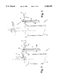
- FIGS. 1 to 15 shows schematically the operating steps of the method according to the invention, in a sequence corresponding to a feasible embodiment thereof;
- FIG. 16 shows the detail, in plan view, of the movable unit (E) which supports the semicrown (8) receiving the members intended to remove and transfer the stitches from the needles (2) of the first series to those (2) of the second series, according to a feasible embodiment: in Y said movable unit being in operative condition, in correspondence of the textile head of the machine, whereas in Z, the same unit being in inoperative condition outside the working area of the needles;
- FIGS. 17A and 17B show the detail of a stitch-removing and transferring member, respectively in side and top view
- FIGS. 17C and 17D show the detail of a closing peg associated to the member of FIG. 17A, respectively in side and top view;
- FIGS. 17E and 17F show, associated to each other, the members of FIGS. 17A-17D during the removal/release of the stitches, respectively in side and top view;
- FIGS. 17G and 17H show the members of FIGS. 17E and 17F, in the same order of representation, in a stitches-gripping attitude;
- FIGS. 17I and 17L show two further embodiments of the removal member of the preceding figures
- FIG. 18 is in plan view, the textile machine of the circular knitting machine, showing the needles (2, 20) and the sinkers cover (51) on which the sliding cams (6, 7) are mounted for the operation of the stitches-removing and transferring members--the cam on the left side in the figure being provided for moving said members close to the working area of the needles and the cam (7) on the right side serving to move said members away therefrom--the trajectory, indicated by the arrow T, of the members for the removal and transfer of the stitches and, indicated by dotted lines in correspondence of cam (6), the trajectory of the portions of these members associated to the cam (6);
- FIG. 19 is a view similar to FIG. 18 but showing the cam (6) out of operation and the cam (7) in operation;
- FIG. 20 shows in plan view the movable unit (E) with the respective bearing arm (G), with the above said semicrown (8), means (808, 809) for the transmission of motion of the needles cylinder to the semicrown, the cam (9) for overturning the semicrown (8) and respective drive means (90) and slide guide means (91);
- FIG. 21 is a section view of the knitting machine, with the apparatus according to the invention in operating condition and the plate (3) outside the working area of the needles, which also shows the ring (800) for supporting the semicrown (8) and the means for driving the semicrown into motion;
- FIG. 22 shows an enlarged detail of the means of FIG. 21
- FIG. 23 is a plan view of the stitches-removing and transferring members and of the means which operate the overturning of the semicrown (8), in a stitches-removing attittude;
- FIG. 24 shows the means of FIG. 23 after the overturning of the semicrown (8)
- FIG. 25 shows a section view of the movable unit (E).
- FIG. 26 shows a diagram relevant to the operation of the means which provide for the overturning of the semicrown (8), in a condition in which the inoperative cam (9) does not hinder the transit of the pivot (83) both before and after the overturning of the semicrown (positions U and V, respectively), that is, when the pivot (83) follows either the inner (TI) or outer (TE) trajectory;
- FIG. 27 shows a diagram like that in FIG. 26, with the cam (9) for the overturning of the semicrown (8) being in operative condition;
- FIGS. 28A-28C show a front view, a plan view and a section view on line N--N, of the semicrown (8);
- FIGS. 29A and 29B show, respectively, a cutaway plan view and a sectional view on line Q--Q of the textile head of the machine embodying an apparatus according to the invention, with means for a temporary support of the stitches already formed by the hooks of the plate, according to an alternative embodiment;
- FIGS. 30-36 show schematically the operating steps of the method according to the invention, in a sequence corresponding to a further possible embodiment
- FIGS. 37 and 38 show respectively a cutaway plan view and a sectional view on line T--T of an apparatus according to a further embodiment of the invention.
- fabric as removed from the hooks (3) of plate (30) and taken up by the members (4), will refer to the proper stitches and/or to the interweaving thread that links two adjacent stitches or loops.
- an operational method according to the invention comprises the following steps:
- a circular machine comprising a cylinder (1) with a plurality of needles (2, 20) so disposed as to define a first and a second series of needles acting, respectively, on corresponding substantially semicylindrical portions (10, 11) of the cylinder: means being provided for the vertical reciprocating motion of the needles (2, 20) according to the predetermined knitting program; the knitting is started by using the needles (2) of said first series, and the formation of the first ranks of stitches--the number of the interested ranks possibly varying in relation to the textile structure to be given to the article--is operated by the withdrawal of the hooks (30) housed in the plate (3) of the machine, so that the hooks pick up the thread together with said needles (2).
- This operation allows the engagement to the hooks (2) and, therefore, to the plate (3) supporting them, of the corresponding toe portion of the article;
- a fabric pocket (ST) is produced, developed over three spatial dimensions and having a substantially conical shape with circular base. This base results with one part of the stitches of the last rank being disposed on the needles (2) of the first series and with the remaining portion of the stitches being suspended to the corresponding hooks (30) of plate (3)--the stitches suspended to the hooks (30) standing above those of needles (2).
- the above mentioned fabric pocket (ST) is situated folded over itself (FIG. 1), the needles (2) of the first series are all in lowered position and any thread used for the knitting is cut.
- the said fabric pocket (ST) is schematically shown only in FIG. 1 of the drawings;
- plate group such as the thread-guide units and the thread-feeding mouths, which could possibly impair the correct execution of the subsequent operating steps;
- removal means (4) able to pick up the fabric removed from the corooks (3) (FIG. 5): said removal means (4) being outside the working area of the needles (2) during the knitting of the pocket (ST)--for example, disposed in a position external to the textile head of the machine--and being disposed in operative condition in the working area of the needles (2) only after the removal of the fabric from the hooks (30) of the plate group (3) and after the moving away of the latter;
- a circular machine for manufacturing tubular knit articles with a cylinder (1) provided with a first and second series of needles (2, 20) acting on corresponding semicylindrical opposite portions (10, 11), with a plate (3.) to which a plurality of hooks (30) are associated to move from and to said needles (2, 20), and with a series of sinkers (5) carried by a crown (510) and operated by cam members (511) of a housing (51) mounted externally to said portions (10, 11) of the cylinder (1). All these members, as well as the respective drive and control means are known per se to those skilled in the art and, therefore, will not be described herein in greater detail;
- the vertically movable suction tube (13) normally provided inside the cylinder (1) may be used, for example, the vertically movable suction tube (13) normally provided inside the cylinder (1).
- the use of said tube (13) also allows supporting the portion of the fabric under treatment at a height that prevents the respective stitches from hooking up members of the textile head.
- the stem (400) of said flat removal elements (4) may be suitably folded or curved to allow the sliding thereof on the walls of the respective guides (81) provided on the support semicrown (8) and, owing to the friction generated upon moving said guides, prevents same stem from being driven into an unwanted motion.
- able to be associated to each of said flat removal members (4) is a movable element apt to completely and irreversibly close the end hook (40) so as to form an eyelet (OR) for retaining the stitches to be taken out and moved on.
- these elements for the closing of the hook (40) are made up of flat members (43) disposed side-by-side to the main members (4), also received into corresponding guiding slits formed in the semicrown (8) and provided with heels (430, 431) to allow them to be driven from and to the needles (2, 20) by means of said cams (6, 7).
- the member for closing the hook (40) of each flat element (4) may consist of a curved, flexible, elastic, filiform body (44)--shown only in FIG. 17L for the sake of simplicity--having its concavity turned opposite to the hook (40) and being welded to the hook (40) and with its free end extending beyond the corresponding end of the flat element (4)
- the body (44) owing to its elasticity, moves away spontaneously from the hook (40) to take up, again spontaneously, the initial covering condition after said gripping has taken place.
- the covering of the hook (40) is e sufficient to avoid the spontaneous removal of the engaged fabric, whereas, upon the transfer of the same fabric onto the second-series needles (20), the force exerted by theese needles (20) will be sufficient to drive the body (44) away from the position for the covering of the hook (40), which hook will again move to the initial covering position after said transfer.
- the means for operating the 180°-overturning of the semicrown (8) comprise, according to the example shown in the figures of the accompanying drawings, a cam (9) of spiroidal profile, developed along a semicricumference external to the semicrown (8) and having a cross-section shaped as a reverse "U" (as illustrated in FIG. 25), mounted for sliding within suitable guide slots (91) provided on the cover (803) of the movable unit (E) and associated to an actuator controlling the translation thereof parallel to itself--as indicated by the arrow GG in FIG.
- the overturning of the semicrown (8) is obtained by disposing the cam (9) at position (L) of FIG. 27.
- Means are also provided to maintain said semicrown (8) adherent to support blocks (80) in an unallowed overturning attitude, with a lever (87) able to rotate about the axis of the pivot (870), trasversally borne by each block (80), and associated to a fixed cam (871) solid to the inner surface of the cover (803): the lower free end (872) of the lever (87) intended to be put in contact with a corresponding portion of the outer edge of the semicrown (8) (as illustrated in FIG. 22) in adhering attitude with blocks (80).
- the lever (80) is normally kept in the position shown in FIG. 22 by a spring (FIG. 22 indicating the axis JJ thereof) housed in each of blocks (80).
- the knitting of the pocket (ST) representing the fabric portion of the stocking intended to form the toe by using only the needles (2) of the first series so that the free edge (the upper one in the figures of the attached drawings) of the pocket (ST) will, as a result, be suspended to the hooks (30) of plate (3).
- the end of the pocket (ST) suspended to the hooks (30) of plate (3) is transferred onto the needles (2) which also have the stitches of the other end thereon.
- the hooks (30) are moved in centrifugal direction to bring the fabric of the corresponding portion of pocket (ST) close to needles (2), and these are raised up to penetrate the fabric, through the spaces between the hooks (30), and reach such a height as to have this fabric below the respective tongues (21).
- the hooks (30) of plate (3) are moved back to the respective initial positions, by means of the relevant driving cams, with a motion opposite to the previous one and, afterwards, the plate (3) is lifted up to be moved away from the working area of the neeldes.
- the semicrown (8), carried by the movable unit (E) is transferred to the knitting station (Y) and so positioned as to result coaxial to the cylinder (1) of needles (2, 20).
- the members (4) for gripping the fabric already suspended to the hooks (30) are made to advance centripetally in succession for a travel of predetermined length, within the respective housings provided in the semicrown (8), by means of the cam (6) and with a rotation of the support (800), this rotation being derived from the shaft (805) via the transmission (807, 808, 809).
- the needles (2) are lowered so as to make said stitches rest on the members (4), in correspondence of hooks (40), to perform the unloading of same stitches, that is, their being taken over by the members (4).
- the stitches transferred from the needles (2) to the members (4) are brought back onto the needles (20) of the second series, by a 180° rotation of the semicrown (8) about the axis (R--R) and subsequent elongation of the fabric operated by the same members (4) which, by means of cam (7), are made to retract, that is, moved in centrifugal direction to dispose themselves in the respective initial positions taken up prior to the removal of the stitches.
- the needles (20) of the second series are thus lifted up, to penetrate the edge of fabric now standing above, and then lowered to drive it downwards to release the stitches from the grip of members (4) which, afterwards, are brought back to the respective initial positions through a movement opposite to the preceding one.
- the movable unit (E) is transferred again to the station (Z), the plate (3) is brought back to its initial condition in order to keep on with the knitting of the article which will thus result with its toe already closed.
- the stitches already suspended to hooks (30) of the plate (3) may be transferred, instead of onto the needles (2) of the first series, onto other members--for example, a front of spines formed by upper appendices of the sinkers (5)--able in any case to make up means for temporary supporting this fabric portion of the pocket (ST) and yet connected to the textile head of the machine, that is, disengaged from the plate (3) to allow the latter to be moved away upon operating the positioning of the movable unit (E), by means of the semicrown (8), in correspondence of the machine's textile head.
- the said means for temporary supporting said fabric portion of the pocket (ST) may consist of means separated from those operating the very formation of said pocket (ST), but still associated thereto.
- the means for temporary supporting the stitches already suspended to the hooks (30) of plate (3) may also consist of a plurality of flat members (55) of a shape substantially equal to that of sinkers (5) and with an upper appendix (550) so dimensioned and shaped as to allow the stitches dispose thereon to be unloaded from said hooks (30), to allow the plate (3) with hooks (30) to be moved away and the removal members (4) to intervene.
- Said flat members may be arranged in such positions as to result sideway disposed to corresponding sinkers (5) and be provided with actuation heels (56), like those (57) of sinkers (5), operable by cam means--not shown in the drawings for sake of simplicity--associated to the sinkers housing (51) and acting on said heels in the same way as they do on sinkers (5).
- FIGS. 30-36 of the accompanying drawings The succession of the operating steps schematiccaly illustrated in FIGS. 30-36 of the accompanying drawings is similar to that relative to the steps previously described with reference to FIGS. 1-8.
- the only major difference, in this case being that in order to tansfer the stitches from the hooks (30) of plate (3) to the members (55) for the temporary support thereof, provision is made for moving radially, with respect to cylinder (1), both the hooks (30) and the flat members (55) either individually or in combination.
- the means for temporary supporting the stitches already suspended to the hooks (30) of plate (3) comprise a plurality of members (219 shaped likewise the needles (2, 20) and disposed side-by-side to corresponding needles, at least on the portion (10) of the cylinder which the needles (2) of the first series act upon.
- the said members (21) can be moved by cam means--not shown in the drawings for sake of simplicity--acting on respective actuation heels (210), so as to drive them in motion parallel to the needles of cylinder (1) also exhibiting actuation heels (200) upon which corresponding cam means, not shown in the drawings, are made to act.
- Said members (219) having an upper appendix (211) able to carry out the same function as the appendix (550) of flat members (55) above described.
- a wire (810) for example, extending along a corresponding slot (811) formed on the portion of minor diameter of the semicrown (8) and suitably folded over 90° in correspondence of the two ends, and of a semicircular listel (812) able to be fixed to the semicrown (8) on the side opposite to that of the wire (810).
- Said wire (810) being easily releasable from the semicrown (8), so that the insertion and possible removal or replacement of the removal means (4) result correspondingly facilitated also without intervening on the Listel (812).
- the wire (810) and the listel (812) act also as forward and, respectively, backward travel limits of removal means (4) within the respective seats of the semicrown (8).
- the seats (81) for removal members (4) are shaped as slits, that is, they are open on both sides of the semicrown (8), in order to act more easily on the respective driving heels both before and after the overturning of same semicrown.
Abstract
Description
Claims (20)
Applications Claiming Priority (2)
| Application Number | Priority Date | Filing Date | Title |
|---|---|---|---|
| IT97FI000265A IT1297377B1 (en) | 1997-12-04 | 1997-12-04 | METHOD AND DEVICE FOR MANUFACTURING TUBULAR TEXTILE PRODUCTS |
| ITFI97A0265 | 1997-12-04 |
Publications (1)
| Publication Number | Publication Date |
|---|---|
| US6105399A true US6105399A (en) | 2000-08-22 |
Family
ID=11352300
Family Applications (1)
| Application Number | Title | Priority Date | Filing Date |
|---|---|---|---|
| US09/204,187 Expired - Lifetime US6105399A (en) | 1997-12-04 | 1998-12-03 | Method and apparatus for manufacturing tubular knitted articles |
Country Status (7)
| Country | Link |
|---|---|
| US (1) | US6105399A (en) |
| EP (1) | EP0924326B1 (en) |
| AT (1) | ATE246275T1 (en) |
| DE (1) | DE69816769T2 (en) |
| ES (1) | ES2203918T3 (en) |
| IT (1) | IT1297377B1 (en) |
| PT (1) | PT924326E (en) |
Cited By (7)
| Publication number | Priority date | Publication date | Assignee | Title |
|---|---|---|---|---|
| US6282925B1 (en) * | 2000-02-28 | 2001-09-04 | Matec S.P.A. | Method for manufacturing closed end tubular items, in particular hosiery, on a circular knitting machine |
| US6381991B2 (en) * | 2000-02-28 | 2002-05-07 | Matec S.P.A. | Method and apparatus for manufacturing tubular items, particularly hosiery items, closed at an axial end |
| US20060144095A1 (en) * | 2002-10-21 | 2006-07-06 | Alberto Frullini | Method and apparatus for joining the edges of a tubular knitted article |
| KR100981096B1 (en) | 2010-02-18 | 2010-09-08 | 주식회사유담 | Cylinder for socks knitting machine |
| US8443633B1 (en) * | 2012-09-05 | 2013-05-21 | Da Kong Enterprise Co., Ltd. | Apparatus and method for transferring loops from the knitting machine needle |
| US20150354108A1 (en) * | 2013-01-16 | 2015-12-10 | Lonati S.P.A. | Method for Closing Automatically an Axial End of a Tubular Manufacture and for Unloading it in an Inside-out Configuration, and Apparatus for performing the Method |
| JP2019525014A (en) * | 2016-07-13 | 2019-09-05 | ロナティ エッセ.ピ.ア. | Pickup device for picking up a tubular knit product from a circular knitting machine for hosiery etc. and transferring this knit product to a unit configured to perform further operations on the knit product |
Citations (5)
| Publication number | Priority date | Publication date | Assignee | Title |
|---|---|---|---|---|
| FR1346518A (en) * | 1962-11-29 | 1963-12-20 | Calze Donnina S P A | Method and device for closing the end opening of tubular knits |
| DE1635992A1 (en) * | 1968-01-02 | 1971-07-29 | Feinstrumpfwerke Esda Veb | Device on single-cylinder circular knitting machines for closing the tip of a stocking made from the same |
| WO1997020089A1 (en) * | 1995-11-28 | 1997-06-05 | Golden Lady S.P.A. | Device for closing one end of a tubular knitted article on the same circular machine that produced it |
| EP0592376B1 (en) * | 1992-10-09 | 1997-07-23 | FABRITEX S.r.l | Method and device for making a connection between the two edges of a knitted tubular product at the end of its formation |
| EP0635593B1 (en) * | 1993-07-12 | 1997-10-15 | FABRITEX S.r.l | Method and device for connecting the two edges of a tubular knitted product during its manufacture |
-
1997
- 1997-12-04 IT IT97FI000265A patent/IT1297377B1/en active IP Right Grant
-
1998
- 1998-12-02 ES ES98830721T patent/ES2203918T3/en not_active Expired - Lifetime
- 1998-12-02 PT PT98830721T patent/PT924326E/en unknown
- 1998-12-02 DE DE69816769T patent/DE69816769T2/en not_active Expired - Fee Related
- 1998-12-02 AT AT98830721T patent/ATE246275T1/en not_active IP Right Cessation
- 1998-12-02 EP EP98830721A patent/EP0924326B1/en not_active Expired - Lifetime
- 1998-12-03 US US09/204,187 patent/US6105399A/en not_active Expired - Lifetime
Patent Citations (5)
| Publication number | Priority date | Publication date | Assignee | Title |
|---|---|---|---|---|
| FR1346518A (en) * | 1962-11-29 | 1963-12-20 | Calze Donnina S P A | Method and device for closing the end opening of tubular knits |
| DE1635992A1 (en) * | 1968-01-02 | 1971-07-29 | Feinstrumpfwerke Esda Veb | Device on single-cylinder circular knitting machines for closing the tip of a stocking made from the same |
| EP0592376B1 (en) * | 1992-10-09 | 1997-07-23 | FABRITEX S.r.l | Method and device for making a connection between the two edges of a knitted tubular product at the end of its formation |
| EP0635593B1 (en) * | 1993-07-12 | 1997-10-15 | FABRITEX S.r.l | Method and device for connecting the two edges of a tubular knitted product during its manufacture |
| WO1997020089A1 (en) * | 1995-11-28 | 1997-06-05 | Golden Lady S.P.A. | Device for closing one end of a tubular knitted article on the same circular machine that produced it |
Cited By (9)
| Publication number | Priority date | Publication date | Assignee | Title |
|---|---|---|---|---|
| US6282925B1 (en) * | 2000-02-28 | 2001-09-04 | Matec S.P.A. | Method for manufacturing closed end tubular items, in particular hosiery, on a circular knitting machine |
| US6381991B2 (en) * | 2000-02-28 | 2002-05-07 | Matec S.P.A. | Method and apparatus for manufacturing tubular items, particularly hosiery items, closed at an axial end |
| US20060144095A1 (en) * | 2002-10-21 | 2006-07-06 | Alberto Frullini | Method and apparatus for joining the edges of a tubular knitted article |
| US7107797B2 (en) * | 2002-10-21 | 2006-09-19 | Fabritex S.R.L | Method and apparatus for joining the edges of a tubular knitted article |
| KR100981096B1 (en) | 2010-02-18 | 2010-09-08 | 주식회사유담 | Cylinder for socks knitting machine |
| US8443633B1 (en) * | 2012-09-05 | 2013-05-21 | Da Kong Enterprise Co., Ltd. | Apparatus and method for transferring loops from the knitting machine needle |
| US20150354108A1 (en) * | 2013-01-16 | 2015-12-10 | Lonati S.P.A. | Method for Closing Automatically an Axial End of a Tubular Manufacture and for Unloading it in an Inside-out Configuration, and Apparatus for performing the Method |
| US10011928B2 (en) * | 2013-01-16 | 2018-07-03 | Lonati S.P.A. | Method for closing automatically an axial end of a tubular manufacture and for unloading it in an inside-out configuration, and apparatus for performing the method |
| JP2019525014A (en) * | 2016-07-13 | 2019-09-05 | ロナティ エッセ.ピ.ア. | Pickup device for picking up a tubular knit product from a circular knitting machine for hosiery etc. and transferring this knit product to a unit configured to perform further operations on the knit product |
Also Published As
| Publication number | Publication date |
|---|---|
| IT1297377B1 (en) | 1999-09-01 |
| EP0924326B1 (en) | 2003-07-30 |
| ITFI970265A1 (en) | 1999-06-04 |
| ITFI970265A0 (en) | 1997-12-04 |
| PT924326E (en) | 2003-12-31 |
| EP0924326A2 (en) | 1999-06-23 |
| EP0924326A3 (en) | 2000-05-24 |
| ATE246275T1 (en) | 2003-08-15 |
| DE69816769D1 (en) | 2003-09-04 |
| DE69816769T2 (en) | 2004-04-15 |
| ES2203918T3 (en) | 2004-04-16 |
Similar Documents
| Publication | Publication Date | Title |
|---|---|---|
| US6164091A (en) | Method and apparatus for seaming edges of knitted articles | |
| US5570591A (en) | Method and apparatus for seaming two edges of a knitted tubular article upon completion thereof | |
| EP2024544B1 (en) | Method and integrated system for knitting a stocking on a circular knitting machine and for closing the toe of the stocking | |
| US5487281A (en) | Method and apparatus for joining two edges of a knitted tubular article | |
| EP0679746B1 (en) | Device for handling knitted products manufactured on circular stocking knitting machines | |
| KR102596015B1 (en) | Apparatus and method for picking up a tubular knitted article from a circular knitting machine | |
| US20100313607A1 (en) | Method and apparatus for closing a tubular knitted article at one of its axial ends, at the end of its production cycle on a circular knitting machine for hosiery or the like | |
| CN101454492A (en) | Machine for automatically closing the end edge of a knitted tubular fabric, such as a stocking or a sock | |
| JP2014530304A (en) | A method of preparing a tubular product for automatic pick-up upon completion of the formation of a tubular product such as a sock product on a double cylinder circular knitting machine having at least one feed or drop, and such a method Double cylinder circular knitting machine to do | |
| EP3374554B1 (en) | Method for preparing a tubular article, such as a sock or the like, for automated pickup at the end of its forming on a double cylinder circular machine with at least one feed or drop, and double cylinder circular machine for the execution thereof | |
| US6105399A (en) | Method and apparatus for manufacturing tubular knitted articles | |
| US5551260A (en) | Method for joining two edges of a knitted tubular article upon completion thereof | |
| US4689971A (en) | Process and circular knitting machine for manufacturing pantyhose articles and the like | |
| US6155081A (en) | Apparatus for driving stitches of textile articles | |
| US5226297A (en) | Knitting machine for producing tights (pantihose) | |
| EP0803599B1 (en) | Single-cylinder circular hosiery-making or knitting machine particularly for manufacturing tubular items closed at one of their axial ends | |
| US4864833A (en) | Control device for adjusting the radial position of the sinkers in a circular knitting machine | |
| KR102656125B1 (en) | A pick-up device for picking up tubular knitted articles from a circular knitting machine and delivering the articles to a unit adapted to perform further operations on the articles. | |
| EP0010982B1 (en) | Method of and mechanism for transferring knitted fabric from a knitting machine to a magazine | |
| CN113825868B (en) | Method and apparatus for producing a tubular knitted article with closed toe | |
| US4369638A (en) | Method and apparatus for knitting hollow articles | |
| EP0229333A2 (en) | Device to be applied on circular knitting machines for making stocking elements with stretched cuffs and adapted for locking the cuff and reversing the stocking elements being formed | |
| EP0115060A1 (en) | A knitwork tensioning device for a knitting machine |
Legal Events
| Date | Code | Title | Description |
|---|---|---|---|
| AS | Assignment |
Owner name: SANGIACOMO S.P.A. (30%), ITALY Free format text: ASSIGNMENT OF ASSIGNORS INTEREST;ASSIGNORS:FRULLINI, ALBERTO;FRULLINI, PAOLO;REEL/FRAME:010348/0568 Effective date: 19981123 Owner name: FABRITEX S.R.L. (70%), ITALY Free format text: ASSIGNMENT OF ASSIGNORS INTEREST;ASSIGNORS:FRULLINI, ALBERTO;FRULLINI, PAOLO;REEL/FRAME:010348/0568 Effective date: 19981123 |
|
| STCF | Information on status: patent grant |
Free format text: PATENTED CASE |
|
| REMI | Maintenance fee reminder mailed | ||
| FPAY | Fee payment |
Year of fee payment: 4 |
|
| SULP | Surcharge for late payment | ||
| FPAY | Fee payment |
Year of fee payment: 8 |
|
| FEPP | Fee payment procedure |
Free format text: PAT HOLDER NO LONGER CLAIMS SMALL ENTITY STATUS, ENTITY STATUS SET TO UNDISCOUNTED (ORIGINAL EVENT CODE: STOL); ENTITY STATUS OF PATENT OWNER: LARGE ENTITY |
|
| FPAY | Fee payment |
Year of fee payment: 12 |