US609727A - Railway - Google Patents
Railway Download PDFInfo
- Publication number
- US609727A US609727A US609727DA US609727A US 609727 A US609727 A US 609727A US 609727D A US609727D A US 609727DA US 609727 A US609727 A US 609727A
- Authority
- US
- United States
- Prior art keywords
- frog
- rail
- plate
- track
- rib
- Prior art date
- Legal status (The legal status is an assumption and is not a legal conclusion. Google has not performed a legal analysis and makes no representation as to the accuracy of the status listed.)
- Expired - Lifetime
Links
- 241000269350 Anura Species 0.000 description 1
- 238000013459 approach Methods 0.000 description 1
- 238000010276 construction Methods 0.000 description 1
- 230000000994 depressogenic effect Effects 0.000 description 1
Images

Classifications
-
- A—HUMAN NECESSITIES
- A63—SPORTS; GAMES; AMUSEMENTS
- A63H—TOYS, e.g. TOPS, DOLLS, HOOPS OR BUILDING BLOCKS
- A63H19/00—Model railways
- A63H19/30—Permanent way; Rails; Rail-joint connections
- A63H19/32—Switches or points; Operating means therefor
Definitions
- IINrTnn STATES PATENT OFFICE.
- My invention relates to railways, and more particularly to improvements in connection with frogs therefor and mechanism for operating the same by the train.
- My object is to provide a structure in which but few parts are employed, and these parts are so constructed and arranged that positive operation is assured and binding of the parts made impossible.
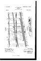
- Figure l is a plan View of a portion of a railway with my present invention applied, the main track being shown clear.
- Fig. 2 is a similar view showing the siding clear.
- Fig. 3 is a longitudinal sectional elevation on the line 3 3 of Fig. 2
- Fig. 4 is a transverse sectional elevation on the line 4 4of Fig. 1.
- A represents the main track, comprising the rails a ct', and C the siding or other line, branching from the main line, said siding comprising the rails c c and the guardrail c2 on the inner side of the outer rail.
- the rails of the main track are not cut at the point of the frog, and for a purpose to be more fully herein described the inner rail c' of the siding joins the inner rail a of the main track and is preferably secured thereto.
- E is the frogerail, suitably pivoted to one of the ties I at a point between the rails of the main track, the said frog having move nient in a horizontal plane and being normally held away from the inner rail ct of said main track by a suitable spring or springs K between the rail ct and the frog.
- the frog is pivoted at its end farthest from the siding, and at this end is of the general structure and height of the rails of the main track. Toward its free end, however, the tread of the frog gradually widens and its height gradually increases. At its free end the frog is cut away to produce an angular member, having the tread e for one face and the depending web e' for the other. Vhen the frog is thrown to clear the siding, its web lies against the inner face of the rail a, and its tread rests upon the tread of said rail and 6o upon the portion of the rail c' of the siding which adjoins the said rail a of the main track. A bearing-surface is thus produced by the rails for the tread of the free end of the' frog.
- the web of the frog is an- 65 guiar, as shown, so that when it is thrown to clear the siding all of the web from which the tread projects lies against the rail ct, thus permitting the extending portion of the tread to besupported throughout its entire length.
- the rail c is raised by means of platest ,upon the ties or otherwise to such aheight that its portion adjoining the frog is level with the 'tread of said frog, but the end of said rail c which adjoins the ⁇ rail ot iscut away, so that it presents a portion c3 of the height of Vthe rail a, this portion c3 being a part of the rest for the free end ⁇ of the frog-tread.
- the frog can, if desired, be raised by the plates t" upon the appropriate ties.
- a plate M is by means of the lugs m, eX tending horizontally from its ends in the direction of its length, suitably journaled, as in the brackets t2, (here shown as secured to 9o ties,) along the 'outer side of the outer rail of the siding, and a straight rib m extends the length of said plate along its inner side-'z'. e., the side toward the rail c.
- a suitable number of lugs m2 and e2 de- ⁇ 95 pend, respectively, from the plate M and the frog E, and links are pivoted to said lugs, so that the plate and frog move together.
- the spring between the frog and the rail a holds the frog normally in such position that roo the main track is clear, and in this position, as shown in Figs. l and 4, the plate M is turned outwardly, so that rib fm' is raised above the level of the rail c.
- This rib is not, however, carried beyond the reach of the tread of the car-wheels which run upon the rail c, and when, the switch having been thrown, a train moving upon the siding-rails from the direction of the pivoted end 0f the frog reaches the corresponding end of the plate the tread of the first wheel engages the rib and throws the plate inwardly until the rib is level with the rail c, this movement acting through the links @c to throw the frog in position to clear the siding.
- the rib prevents the top face of the plate from engaging the tread of the wheels and thus obstructing full pivotal movement of the said plate.
- the sprin g returns the frog to the position to clear the main track. The operation when a train approaches the frog from the direction opposite to that just described is apparent.
- the ends of said rib are beveled, as shown at m3, and the rib is of a length greater than the distance between the trucks either of a car or of adjoining cars, so that before the wheels of one truck leave the rib it is engaged by the Wheels of the succeeding truck.
- a track In a railway or the like, a track, a plate along the side of one of the rails of said track and projecting above said rail, said plate having a straight upper surface, brackets along the track-rail, pivotal lugs between the plate ends and the brackets whereby the plate is pivoted to swing about its longitudinal axis, and connections between said plate and a movable member, as a frog, whereby motion given the plate is transmitted to the movable member; substantially as described.
- a track In a railway or the like, a track, a plate along the side of one of the rails of said track, a rib integral with said plate and projecting therefrom above the track-rail, said rib having a straight upper surface, brackets along the track-rail, pivotal lugs between the plate ends and the brackets whereby the plate is pivoted to swing about its longitudinal axis, and connections between said plate and a movable member, as a frog, whereby motion given the plate is transmitted to the movable member; substantially as described. 3.
- a main track In a railway or the like, a main track, a track branching therefrom, a frog pivoted between the rails of the main track to swing in a horizontal plane to clear either the main track or the branch track, a spring between the frog and a rail of the main track whereby the frog is normally7 held in such position that the main track is clear, a plate along one of the rails of the branch track and having a straight upper portion projecting above the said branch-track rail, brackets along the said rail, lugs upon the plate ends journaled in the brackets wherebythe plate is adapted to swing about its longitudinal axis, and connections between the plate and the frog for moving the said members one by the other; substantially as described.
Landscapes
- Train Traffic Observation, Control, And Security (AREA)
Description
Patented Aug. 23, |898.
C. H. BALLIETTE.
RAILWAY.
(Application filed Dec. 20, 1897.) (No Model.) 2 Sheets- Sheet l.
@MA/.Mmm
No. 609,727. Patented Aug. 23, |898..
C. H. BALLIETTE.
RAILWAY.
(Appliation Bled IIDec.` 20, 1897.) (No Model.) 2 Sheets- Sheet 2.
IINrTnn STATES PATENT OFFICE.
CHARLES II. BALLIETTE, OF CARLISLE, PENNSYLVANIA, ASSIGNOR OF ONE- IIALF TO ABRAHAM B. DUNKLE, OF STEELTON, PENNSYLVANIA.
RAILWAY.
SPECIFICATION forming parser-Letters Patent No. 609,727, dated August e3, 189s. Application led December 20, 1897. Serial No. 662,682. (No model.)
My invention relates to railways, and more particularly to improvements in connection with frogs therefor and mechanism for operating the same by the train.
My object is to provide a structure in which but few parts are employed, and these parts are so constructed and arranged that positive operation is assured and binding of the parts made impossible.
To these ends and also to generally improve upon structures of the character indicated the invention consists in the various matters hereinafter described and claimed.
In the accompanying drawings, Figure l is a plan View of a portion of a railway with my present invention applied, the main track being shown clear. Fig. 2 is a similar view showing the siding clear. Fig. 3 is a longitudinal sectional elevation on the line 3 3 of Fig. 2, and Fig. 4 is a transverse sectional elevation on the line 4 4of Fig. 1.
Referring now more particularly to these drawings, A represents the main track, comprising the rails a ct', and C the siding or other line, branching from the main line, said siding comprising the rails c c and the guardrail c2 on the inner side of the outer rail. The rails of the main track are not cut at the point of the frog, and for a purpose to be more fully herein described the inner rail c' of the siding joins the inner rail a of the main track and is preferably secured thereto. p 4
E is the frogerail, suitably pivoted to one of the ties I at a point between the rails of the main track, the said frog having move nient in a horizontal plane and being normally held away from the inner rail ct of said main track by a suitable spring or springs K between the rail ct and the frog.
The frog is pivoted at its end farthest from the siding, and at this end is of the general structure and height of the rails of the main track. Toward its free end, however, the tread of the frog gradually widens and its height gradually increases. At its free end the frog is cut away to produce an angular member, having the tread e for one face and the depending web e' for the other. Vhen the frog is thrown to clear the siding, its web lies against the inner face of the rail a, and its tread rests upon the tread of said rail and 6o upon the portion of the rail c' of the siding which adjoins the said rail a of the main track. A bearing-surface is thus produced by the rails for the tread of the free end of the' frog. r In fact, the web of the frog is an- 65 guiar, as shown, so that when it is thrown to clear the siding all of the web from which the tread projects lies against the rail ct, thus permitting the extending portion of the tread to besupported throughout its entire length. 7o
The rail c is raised by means of platest ,upon the ties or otherwise to such aheight that its portion adjoining the frog is level with the 'tread of said frog, but the end of said rail c which adjoins the `rail ot iscut away, so that it presents a portion c3 of the height of Vthe rail a, this portion c3 being a part of the rest for the free end` of the frog-tread. The frog can, if desired, be raised by the plates t" upon the appropriate ties.
The construction of the :rails and frog, together with the manner in which either the main track or the siding is rendered clear by the position of said frog, being apparent, the mechanism for operating the frog by the train is now to be considered.
A plate M is by means of the lugs m, eX tending horizontally from its ends in the direction of its length, suitably journaled, as in the brackets t2, (here shown as secured to 9o ties,) along the 'outer side of the outer rail of the siding, and a straight rib m extends the length of said plate along its inner side-'z'. e., the side toward the rail c.
A suitable number of lugs m2 and e2 de-` 95 pend, respectively, from the plate M and the frog E, and links are pivoted to said lugs, so that the plate and frog move together. The spring between the frog and the rail a holds the frog normally in such position that roo the main track is clear, and in this position, as shown in Figs. l and 4, the plate M is turned outwardly, so that rib fm' is raised above the level of the rail c. This rib is not, however, carried beyond the reach of the tread of the car-wheels which run upon the rail c, and when, the switch having been thrown, a train moving upon the siding-rails from the direction of the pivoted end 0f the frog reaches the corresponding end of the plate the tread of the first wheel engages the rib and throws the plate inwardly until the rib is level with the rail c, this movement acting through the links @c to throw the frog in position to clear the siding.
It will be noticed that the rib prevents the top face of the plate from engaging the tread of the wheels and thus obstructing full pivotal movement of the said plate. During the passage of the train over the rib it is held in its lower position and the frog remains in the position above indicated; but as soon as the last wheel of the train leaves the rib the sprin g returns the frog to the position to clear the main track. The operation when a train approaches the frog from the direction opposite to that just described is apparent.
In order to facilitate the engagement of the first wheel with the rib, the ends of said rib are beveled, as shown at m3, and the rib is of a length greater than the distance between the trucks either of a car or of adjoining cars, so that before the wheels of one truck leave the rib it is engaged by the Wheels of the succeeding truck.
There is thus provided a structure which comprises but few parts, while these parts are easily and cheaply made and assembled. Furthermore, the tread of the frog is supported throughout its entire length during the passage of a train, and also the straight plate,with its rib, is pivoted in a simple manner, so that it is easily depressed by the train, thus removing all danger of derailment.
Having thus described my inventi0n,what I claim as new, and desire to secure by Letters Patent, is-
1'. In a railway or the like, a track, a plate along the side of one of the rails of said track and projecting above said rail, said plate having a straight upper surface, brackets along the track-rail, pivotal lugs between the plate ends and the brackets whereby the plate is pivoted to swing about its longitudinal axis, and connections between said plate and a movable member, as a frog, whereby motion given the plate is transmitted to the movable member; substantially as described.
2. In a railway or the like, a track, a plate along the side of one of the rails of said track, a rib integral with said plate and projecting therefrom above the track-rail, said rib having a straight upper surface, brackets along the track-rail, pivotal lugs between the plate ends and the brackets whereby the plate is pivoted to swing about its longitudinal axis, and connections between said plate and a movable member, as a frog, whereby motion given the plate is transmitted to the movable member; substantially as described. 3. In a railway or the like, a main track, a track branching therefrom, a frog pivoted between the rails of the main track to swing in a horizontal plane to clear either the main track or the branch track, a spring between the frog and a rail of the main track whereby the frog is normally7 held in such position that the main track is clear, a plate along one of the rails of the branch track and having a straight upper portion projecting above the said branch-track rail, brackets along the said rail, lugs upon the plate ends journaled in the brackets wherebythe plate is adapted to swing about its longitudinal axis, and connections between the plate and the frog for moving the said members one by the other; substantially as described.
In testimony whereof I afl-ix my signature in presence of two witnesses.
CHARLES H. BALLIETTE.
WVitnesses:
C. E. WELLS, J. G. KELLER.
Publications (1)
| Publication Number | Publication Date |
|---|---|
| US609727A true US609727A (en) | 1898-08-23 |
Family
ID=2678344
Family Applications (1)
| Application Number | Title | Priority Date | Filing Date |
|---|---|---|---|
| US609727D Expired - Lifetime US609727A (en) | Railway |
Country Status (1)
| Country | Link |
|---|---|
| US (1) | US609727A (en) |
-
0
- US US609727D patent/US609727A/en not_active Expired - Lifetime
Similar Documents
| Publication | Publication Date | Title |
|---|---|---|
| US609727A (en) | Railway | |
| US245389A (en) | myers | |
| US121158A (en) | Improvement in railway switches | |
| US205369A (en) | Improvement in rail-joints | |
| US367967A (en) | dwiaht | |
| US77456A (en) | Improvement in railroads | |
| US563027A (en) | Spring-rail frog | |
| US1222577A (en) | Railway-switch. | |
| US193206A (en) | Improvement in railroad-switches | |
| US139827A (en) | Improvement in railroad switches | |
| US339411A (en) | Automatic railroad-switch | |
| US275038A (en) | Ors to themselves | |
| US353708A (en) | Railroad-switch | |
| US539575A (en) | William s | |
| US889485A (en) | Railway-switch. | |
| US931493A (en) | Removable crossover. | |
| US324773A (en) | Samuel ii | |
| US580677A (en) | Railroad-switch | |
| US1195892A (en) | Operated switch | |
| US1416458A (en) | Switch frog | |
| US618055A (en) | Railroad-switch | |
| US553934A (en) | Frogless switch | |
| US906544A (en) | Railway-frog. | |
| US949693A (en) | Safety-switch. | |
| US364267A (en) | Albert d |