US609686A - lovejoy - Google Patents
lovejoy Download PDFInfo
- Publication number
- US609686A US609686A US609686DA US609686A US 609686 A US609686 A US 609686A US 609686D A US609686D A US 609686DA US 609686 A US609686 A US 609686A
- Authority
- US
- United States
- Prior art keywords
- caisson
- chamber
- water
- working chamber
- pipes
- Prior art date
- Legal status (The legal status is an assumption and is not a legal conclusion. Google has not performed a legal analysis and makes no representation as to the accuracy of the status listed.)
- Expired - Lifetime
Links
- XLYOFNOQVPJJNP-UHFFFAOYSA-N water Substances O XLYOFNOQVPJJNP-UHFFFAOYSA-N 0.000 description 30
- 238000011068 load Methods 0.000 description 28
- 239000000463 material Substances 0.000 description 16
- PCHJSUWPFVWCPO-UHFFFAOYSA-N gold Chemical group [Au] PCHJSUWPFVWCPO-UHFFFAOYSA-N 0.000 description 14
- 239000010931 gold Substances 0.000 description 14
- 229910052737 gold Inorganic materials 0.000 description 14
- 239000004576 sand Substances 0.000 description 12
- 239000010970 precious metal Substances 0.000 description 6
- 239000011435 rock Substances 0.000 description 6
- 240000007600 Lysimachia clethroides Species 0.000 description 4
- 238000010438 heat treatment Methods 0.000 description 4
- XEEYBQQBJWHFJM-UHFFFAOYSA-N iron Chemical compound [Fe] XEEYBQQBJWHFJM-UHFFFAOYSA-N 0.000 description 4
- 230000035693 Fab Effects 0.000 description 2
- 230000000875 corresponding Effects 0.000 description 2
- 238000007599 discharging Methods 0.000 description 2
- 229910052742 iron Inorganic materials 0.000 description 2
- 238000000034 method Methods 0.000 description 2
- 238000005192 partition Methods 0.000 description 2
- 230000000284 resting Effects 0.000 description 2
- 239000002965 rope Substances 0.000 description 2
- 239000007787 solid Substances 0.000 description 2
- 239000004575 stone Substances 0.000 description 2
Images

Classifications
-
- E—FIXED CONSTRUCTIONS
- E02—HYDRAULIC ENGINEERING; FOUNDATIONS; SOIL SHIFTING
- E02D—FOUNDATIONS; EXCAVATIONS; EMBANKMENTS; UNDERGROUND OR UNDERWATER STRUCTURES
- E02D23/00—Caissons; Construction or placing of caissons
- E02D23/04—Pneumatic caissons
- E02D23/06—Bringing persons or material into or out of compressed air caissons
Definitions
- TH aims Pncns co. Now-umu. wnsnmsfou. n. c.
- the object of the invention is to provide a new and improved caisson more especially designed for use on frozen ground, in rivers, streams, and other waterways having bottoms of gold-bearing sand, the caisson being arranged to permit of floating it about from one place to another, to sink or raise it at will, and to provide a comfortable working chamber for miners to work in when the caisson is in a lowermost position to obtain the precious metal from the gold-bearing sand.
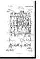
- Figure l is a sectional side elevation of the improvement on the linel l of Fig. 2.
- Fig. 2 is a plan view of the improvement.
- Fig. 3 is a transverse section of the same on the line 3 3 of Fig. 1, and
- Fig. t is a sectional plan view of the same on the line 4 4 of Fig. l.
- the movable caisson hereinafter more fully described is more especially designed for use in the Klondike and other northern regions where the ground even down to bed-rock is almost throughout the year in a frozen state and it becomes necessary for a miner to first remove a large amount of frozen material before the goldbearing material is reached.
- the only practif cable way to handle this frozen material is to first thaw it out and then treat the thawed material the same as ordinary gold-bearing sand to obtain the precious metal.
- the object of the movable caisson presently to be described in detail.
- the working chamber C is provided with a bottom formed principally of a series of doors F, each adapted to be swung into an open position, as indicated at the left in Fig. 3, to permit the miners in the chamber C to reach the sand in the sand-bed, in which the lower end of the casing is embedded.
- Each of the doors F is connected with the lower end of a rope or chain F', passing over pulleys F2 to a windlass F3 on the deck E, so that thedoor F can be readily raised or swung into an open position from the deck of the casing, as hereinafter more fully described.
- the doors F are made hollow to form steamspaces, and the sides G of the chamber C are likewise made hollow to form steam-spaces, said hollow sides being connected by pipes H' with the interior of the doors F, so that steam introduced into the sides Giv by the pipes H can also pass into the doors F, so that the sides and bottom of the chamber C are heated, and as the said sides and bottoms come in contact with the material the latter is readily thawed out to permit of conveniently working it to obtain the gold-bearing sand.
- the pipes H extend to the deck E and are connected at their 'upper ends with a suitable steam-supply either on the caisson or on a separate iioat or on shore, as the case may be.
- FIG. 3 two rows of doors F are employed, hinged to the sides of the chamber and resting with their free ends on a longitudinally-extending hollow beam F4, forming part of the bottom of the chamber.
- Access is had to the working chamber C through an air-shaft I, extending from the partition B upward beyond the deck E, and in the said air-shaft are arranged air-locks I' l2 I3, of which the lower one opens down into the chamber C.
- valved pipes J which open at their lower ends into the river, the valves of the pipes having their stems J extended up through a pipe J2, which leads from near the bottoni of the chamber Cinto the compartment D.
- Suitable branch pipes J 3 extend from the pipe J2 into the compartment D.
- the latter may be separated by cross-partitions into small compartments, each of which is connected with one or more pipes J3 by the pipe J2.
- the upper end of the stem J is within reach of an operator on the deck E, so that the valves in the pipes J can be opened to allow water to fiow from the river into the workingchamber C at the time the bottom doors F are closed.
- valves in the branch pipes J 3 are closed and the valves in i the pipes J opened to allow the water to iiow through the pipes J back into the river when the air-pressure is on the water in the chamber.
- An air-pipe K opens into the upper portion l of the chamber C and extends through the4 compartment D to the deck E, to be connected there with a suitable source of compressed-air supply either on the caisson or on a ioat or on shore, as the case may be.v
- each discharge-pipe N lead from the chamber C up through the compartment D and deck E to terminate at their upper ends in a gooseneck N', which discharges over the side of the casing' A into the river.
- the lower end of each pipe N is formed with an adjustable flexible sleeve N2, the lower end of which is brought into the tailings, so that the latter are forced by compressed air through the sleeve and up the pipe N and gooseneck N to be finally disharged back into the river.
- the caisson is in the form of a floating vessel, readily iioated about from one place to another.
- the thawed ground can now be easily manipulated in the usual manner to separate the precious metal from the gold, the tailings being brought to the discharge-nozzle N2 and forced up through the latter into and up the pipe N by the compressed air contained in the chamber C.
- the tailings are readily removed from the working chamber, and the gold is removed from time to time either by being carried up through the air-shaft I or by special buckets or elevators.
- valved pipes L As the caisson is relieved gradually of its water-load it rises, and the water-compartment D below the valved pipes L is then discharged by opening the lower valve-pipes L', so that the caisson is finally relieved of nearly all the water and forms a floating vessel which can be readily towed to another place.
- the abovedescribed operation is then repeated-that is, the valved pipes L are closed, the valved pipes J are opened to fill the working chamber C with waterto sink the caisson, and then the water isforced out of the working chamber into the compartment D to load the latter and keep the caisson down.
- a caisson provided with a shell or casing, a working chamber in the lower portion of the casing, and a water-loading compartment above the working chamber and adapted to be filled with water from the said chamber to form a deck-load to keep the casing in position, substantially as shown and described.
- Acaisson provided with a casing, a working chamber in the lower portion of the said casing, and provided with doors in the bottom for opening the chamber to the sand-bed, and when closed permitting of converting the caisson into a Iloating vessel, and an air-supply for the said working chamber for forcing the water out of the chamber at the time the doors are closed, and for keeping the riverwater out of the chamber when the doors are opened,substantially as shown and described.
- a caisson provided with a casing, a water-loading compartment in the upper portion of the casing, a Working chamber in the lower part of the casing, a compressed-air-supply pipe opening into the working chamber, and water-pipes leading from the working chamber to the loading-compartment, so that the water is forced by the compressed air from the working chamber into the loading-compartment, substantially as shown and described.
- a caisson provided with a casing, a water-loading compartment in the upper portion of the casing, a working chamber in the lower part of the casing, a compressed-air-supply pipe opening into the working chamber, water-pipesleadiug from the working chamber into the loading-compartment, so that the Wa ter is forced by the compressed air from the working chamber into the loading-compartment, and doors in the bottom of the said working chamber, to give access to the sand in the bed of the waterway, substantially as shown and described.
- a caisson provided with a casing, a working chamber in the lower portion of the casing, a water-loading compartment in the upper part of the casing, means for emptying the water from the working chamber into the loading compartment, and means for discharging the water from the loading-compartment to float the caisson, substantially as shown and described.
- a caisson provided with a working chamber havinghollow bottom doors, and means for heating the same to thaw the bed with which the doors are in contact, substantially as shown and described.
- a caisson provided with a working chamber having hollow sides and hollow bottom doors, and means for heating the said sides and doors, substantially as shown and described.
Description
No, 609,686. Patented Aug. 23, |898. 1 C. C. LOVEJDY.
MUVABL'E CAISSON.
(Application filed Feb. 19, 1898.)
/N VENTO/9 A fr0/mns.'
TH: aims Pncns co. Now-umu. wnsnmsfou. n. c.
No. 609,686. Patented Aug. 23, |898.
C. C. LUVEJOY. C
MDVABLE CAISSOIL (Application med Fab. 19, lesa.) (No Model.) l 2 Sheets-Sheet 2.V
l ATTOHNf me nonms Pneus ca. Waremme.. wnsumcaou. D. c.
NTTED STATES f PATENT OFFICE.
CHARLES CLAYTON LOVEJ OY, OF NEW YORK, N. Y.
MQ'VABL CAISSON.
SPECIFICATION forming part of Letters Patent No. 609,686, dated August 23, 1898. Application filed February 19, 1898. Serial No. 670,889. (No model.)
To @ZZ whom t may concern.-
Be it known that 4I, CHARLEs CLAYTON LOVEJOY, of the city of New York, borough of Manhattan, in the county of New York and State of New York, have invented a new and Improved Movable Caisson, of which the following is a full,clear, and exact description.
The object of the invention is to provide a new and improved caisson more especially designed for use on frozen ground, in rivers, streams, and other waterways having bottoms of gold-bearing sand, the caisson being arranged to permit of floating it about from one place to another, to sink or raise it at will, and to provide a comfortable working chamber for miners to work in when the caisson is in a lowermost position to obtain the precious metal from the gold-bearing sand.
The invention consists of novel features and parts and combinations of the same, as will be described hereinafter and then pointed out in the claims.
Reference is to be had to the accompanying drawings, forming a part of this specification,
in which similar characters of reference indicate corresponding parts in all the figures.
Figure l is a sectional side elevation of the improvement on the linel l of Fig. 2. Fig. 2 is a plan view of the improvement. Fig. 3 is a transverse section of the same on the line 3 3 of Fig. 1, and Fig. t is a sectional plan view of the same on the line 4 4 of Fig. l.
The movable caisson hereinafter more fully described is more especially designed for use in the Klondike and other northern regions where the ground even down to bed-rock is almost throughout the year in a frozen state and it becomes necessary for a miner to first remove a large amount of frozen material before the goldbearing material is reached. Experience has proven that the only practif cable way to handle this frozen material is to first thaw it out and then treat the thawed material the same as ordinary gold-bearing sand to obtain the precious metal. In order to facilitate the thawing-out process and to enable the miner to comfortably work in winter and summer and to at once handle the material and separate the gold from the tail ings is the object of the movable caisson, presently to be described in detail.
able deck E.- The working chamber C is provided with a bottom formed principally of a series of doors F, each adapted to be swung into an open position, as indicated at the left in Fig. 3, to permit the miners in the chamber C to reach the sand in the sand-bed, in which the lower end of the casing is embedded. Each of the doors F is connected with the lower end of a rope or chain F', passing over pulleys F2 to a windlass F3 on the deck E, so that thedoor F can be readily raised or swung into an open position from the deck of the casing, as hereinafter more fully described. v
y The doors F are made hollow to form steamspaces, and the sides G of the chamber C are likewise made hollow to form steam-spaces, said hollow sides being connected by pipes H' with the interior of the doors F, so that steam introduced into the sides Giv by the pipes H can also pass into the doors F, so that the sides and bottom of the chamber C are heated, and as the said sides and bottoms come in contact with the material the latter is readily thawed out to permit of conveniently working it to obtain the gold-bearing sand. The pipes H extend to the deck E and are connected at their 'upper ends with a suitable steam-supply either on the caisson or on a separate iioat or on shore, as the case may be.
As illustrated in Fig. 3, two rows of doors F are employed, hinged to the sides of the chamber and resting with their free ends on a longitudinally-extending hollow beam F4, forming part of the bottom of the chamber. Access is had to the working chamber C through an air-shaft I, extending from the partition B upward beyond the deck E, and in the said air-shaft are arranged air-locks I' l2 I3, of which the lower one opens down into the chamber C. The air=locks are successively opened and closed to permit the miners to pass down into the chamber C, filled with compressed air while in use, the shaft, as Well as the chamber, being provided with suitable ladders I4 to permit the operators to readily pass down into the chamber and up the shaft or down the same, as the case may be.
In the hollow beam F4 are arranged a number of valved pipes J, which open at their lower ends into the river, the valves of the pipes having their stems J extended up through a pipe J2, which leads from near the bottoni of the chamber Cinto the compartment D. Suitable branch pipes J 3 extend from the pipe J2 into the compartment D. The latter may be separated by cross-partitions into small compartments, each of which is connected with one or more pipes J3 by the pipe J2. The upper end of the stem J is within reach of an operator on the deck E, so that the valves in the pipes J can be opened to allow water to fiow from the river into the workingchamber C at the time the bottom doors F are closed. This is done for filling the chamber with a sufficient amount of water to cause the caisson to settle. Now when air is forced into the chamber C then the pressure on the water forces the latter up ther pipes J2 and through the branch pipes J 3 to l lll the compartments D, the water forming the load to hold the caisson in place.
In winter it is not desirable to ll the compartments with a water-load from the chamber C, and in this case the valves in the branch pipes J 3 are closed and the valves in i the pipes J opened to allow the water to iiow through the pipes J back into the river when the air-pressure is on the water in the chamber.
An equivalent solid load of stone, rock, old iron, &c., is in this case used .in the compartments D instead of the Water-load.
An air-pipe K opens into the upper portion l of the chamber C and extends through the4 compartment D to the deck E, to be connected there with a suitable source of compressed-air supply either on the caisson or on a ioat or on shore, as the case may be.v
From the compartment D lead valved outlet-pipes L L through the wall of the casing A to the outside thereof to relieve the compartment D of its water-load whenever desired, as hereinafter more fully explained. One or more discharge-pipes N lead from the chamber C up through the compartment D and deck E to terminate at their upper ends in a gooseneck N', which discharges over the side of the casing' A into the river. The lower end of each pipe N is formed with an adjustable flexible sleeve N2, the lower end of which is brought into the tailings, so that the latter are forced by compressed air through the sleeve and up the pipe N and gooseneck N to be finally disharged back into the river.
The operation is as follows: When the doors F are closed and the casing A is empty,
the caisson is in the form of a floating vessel, readily iioated about from one place to another. When a desired spot has been reached,
position.
tends a vsuitable distance above the waterlevel. Compressed air is now passed through the pipe K into the working chamber C to force the water therein through the pipes J2 and J 3 into the water-loading compartment D, so as to maintain the caisson in this position 'and at the same time free the working chamber of water` Now in case the river-bed is frozen steam is passed into the sides G and doors F to readily thaw the material covered by the caisson and located in the immediate neighborhood thereof. The doors F are now opened from above, and miners can pass down into the Working chamber C by way of the air-shaft andthe several air-locks. The thawed ground can now be easily manipulated in the usual manner to separate the precious metal from the gold, the tailings being brought to the discharge-nozzle N2 and forced up through the latter into and up the pipe N by the compressed air contained in the chamber C. Thus the tailings are readily removed from the working chamber, and the gold is removed from time to time either by being carried up through the air-shaft I or by special buckets or elevators. (Not shown.) As the digging progresses in the bottom of the chamber C the caisson sinks farther down, so that the entire strata downto bed-rock can be readily worked before moving the caisson to another When the operation is completed at this particular point and it is desired to move the caisson to another place, then the doors F are again closed, the workmen leave the chamber C by way of the shaft I and close the locks therein, and then the upper valved outlet-pipes L are opened to permit the water contained in the compartment D to discharge through the walls of the casing into the river. As the caisson is relieved gradually of its water-load it rises, and the water-compartment D below the valved pipes L is then discharged by opening the lower valve-pipes L', so that the caisson is finally relieved of nearly all the water and forms a floating vessel which can be readily towed to another place. The abovedescribed operation is then repeated-that is, the valved pipes L are closed, the valved pipes J are opened to fill the working chamber C with waterto sink the caisson, and then the water isforced out of the working chamber into the compartment D to load the latter and keep the caisson down.
By dividing the compartment D into small compartments I am enabled to arrange the waterload in such a manner that the caisson is not liable to tilt to one side in case loose material is, encountered at one side of the caissoni IOO Having thus fully described my invention, I claim as new and desire to secure by Letters Patentl. A caisson, provided with a shell or casing, a working chamber in the lower portion of the casing, and a water-loading compartment above the working chamber and adapted to be filled with water from the said chamber to form a deck-load to keep the casing in position, substantially as shown and described. t
2. Acaisson provided with a casing, a working chamber in the lower portion of the said casing, and provided with doors in the bottom for opening the chamber to the sand-bed, and when closed permitting of converting the caisson into a Iloating vessel, and an air-supply for the said working chamber for forcing the water out of the chamber at the time the doors are closed, and for keeping the riverwater out of the chamber when the doors are opened,substantially as shown and described.
3. A caisson provided with a casing, a water-loading compartment in the upper portion of the casing, a Working chamber in the lower part of the casing, a compressed-air-supply pipe opening into the working chamber, and water-pipes leading from the working chamber to the loading-compartment, so that the water is forced by the compressed air from the working chamber into the loading-compartment, substantially as shown and described.
4. A caisson provided with a casing, a water-loading compartment in the upper portion of the casing, a working chamber in the lower part of the casing, a compressed-air-supply pipe opening into the working chamber, water-pipesleadiug from the working chamber into the loading-compartment, so that the Wa ter is forced by the compressed air from the working chamber into the loading-compartment, and doors in the bottom of the said working chamber, to give access to the sand in the bed of the waterway, substantially as shown and described.
5. A caisson provided with a casing, a working chamber in the lower portion of the casing, a water-loading compartment in the upper part of the casing, means for emptying the water from the working chamber into the loading compartment, and means for discharging the water from the loading-compartment to float the caisson, substantially as shown and described.
6. A caisson provided with a working chamber havinghollow bottom doors, and means for heating the same to thaw the bed with which the doors are in contact, substantially as shown and described.
7. A caisson provided with a working chamber having hollow sides and hollow bottom doors, and means for heating the said sides and doors, substantially as shown and described. i
CHARLES CLAYTON LOVEJOY.
Witnesses:
THEO. G. I-Ios'rER, EvERARD BOLTON MARSHALL.
Publications (1)
| Publication Number | Publication Date |
|---|---|
| US609686A true US609686A (en) | 1898-08-23 |
Family
ID=2678303
Family Applications (1)
| Application Number | Title | Priority Date | Filing Date |
|---|---|---|---|
| US609686D Expired - Lifetime US609686A (en) | lovejoy |
Country Status (1)
| Country | Link |
|---|---|
| US (1) | US609686A (en) |
Cited By (3)
| Publication number | Priority date | Publication date | Assignee | Title |
|---|---|---|---|---|
| US5803659A (en) * | 1995-12-08 | 1998-09-08 | Chattey; Nigel | Modular caissons for use in constructing, expanding and modernizing ports and harbors. |
| US5823714A (en) * | 1990-09-06 | 1998-10-20 | Chattey; Nigel | Universal, environmentally safe, modular caisson systems and caisson mudules for use therewith |
| WO2018024429A1 (en) * | 2016-08-01 | 2018-02-08 | IRS Stahlwasserbau Consulting AG | Immersible engine assembly with a protected module |
-
0
- US US609686D patent/US609686A/en not_active Expired - Lifetime
Cited By (5)
| Publication number | Priority date | Publication date | Assignee | Title |
|---|---|---|---|---|
| US5823714A (en) * | 1990-09-06 | 1998-10-20 | Chattey; Nigel | Universal, environmentally safe, modular caisson systems and caisson mudules for use therewith |
| US5803659A (en) * | 1995-12-08 | 1998-09-08 | Chattey; Nigel | Modular caissons for use in constructing, expanding and modernizing ports and harbors. |
| US6017167A (en) * | 1995-12-08 | 2000-01-25 | Chattey; Nigel | Modular caissons for use in constructing, expanding and modernizing ports and harbors |
| US6234714B1 (en) | 1995-12-08 | 2001-05-22 | Nigel Chattey | Pier and wharf structures having means for directly transferring cargo between two vessels or between a vessel and railcars |
| WO2018024429A1 (en) * | 2016-08-01 | 2018-02-08 | IRS Stahlwasserbau Consulting AG | Immersible engine assembly with a protected module |
Similar Documents
| Publication | Publication Date | Title |
|---|---|---|
| US3965687A (en) | Apparatus for anchoring a structure to the floor of a body of water | |
| US609686A (en) | lovejoy | |
| US510713A (en) | Harbor and river bars and shoals | |
| US550244A (en) | Mining apparatus | |
| US1812305A (en) | Recovery of oil from the earth by mining operations | |
| US687830A (en) | Submarine dredger and gold-saving machine. | |
| US1063284A (en) | Dredge-hopper. | |
| US1066993A (en) | Apparatus for pickling meal. | |
| US735387A (en) | Movable dam. | |
| US360959A (en) | Apparatus for excavating tunnels | |
| US616567A (en) | Apparatus for submarine mining and exploration | |
| US1954094A (en) | Foundation construction | |
| US2500354A (en) | Apparatus for controlling silt accumulation | |
| US715768A (en) | Method of constructing and laying subaqueous tunnels. | |
| US635270A (en) | Dredging machinery. | |
| US549586A (en) | rotewell | |
| US3136132A (en) | Means for unwatering graving docks | |
| US989110A (en) | Sinking deep shafts in water-impregnated ground. | |
| US2488074A (en) | Means and method for grouting drilled-in caissons | |
| US2106157A (en) | Gold mining machinery | |
| US235955A (en) | leonard | |
| US360713A (en) | Gold-mining device | |
| US512865A (en) | Earth | |
| US1182446A (en) | Combined coffer-dam and crib. | |
| US751287A (en) | Tunnel construction |