US6086169A - Midwheel assembly for a track type tractor - Google Patents
Midwheel assembly for a track type tractor Download PDFInfo
- Publication number
- US6086169A US6086169A US09/196,044 US19604498A US6086169A US 6086169 A US6086169 A US 6086169A US 19604498 A US19604498 A US 19604498A US 6086169 A US6086169 A US 6086169A
- Authority
- US
- United States
- Prior art keywords
- assembly
- hub
- midwheel
- axle
- wheel
- Prior art date
- Legal status (The legal status is an assumption and is not a legal conclusion. Google has not performed a legal analysis and makes no representation as to the accuracy of the status listed.)
- Expired - Lifetime
Links
Images


Classifications
-
- B—PERFORMING OPERATIONS; TRANSPORTING
- B62—LAND VEHICLES FOR TRAVELLING OTHERWISE THAN ON RAILS
- B62D—MOTOR VEHICLES; TRAILERS
- B62D55/00—Endless track vehicles
- B62D55/08—Endless track units; Parts thereof
- B62D55/14—Arrangement, location, or adaptation of rollers
Definitions
- the present invention relates generally to track type tractors, and more particularly to a midwheel assembly for a track type tractor.
- Each midwheel assembly generally includes a rubber track which forms a loop around a front roller, a number of midwheels, and a rear roller.
- the rear roller rotates and drives the rubber track around a path defined by the rear roller and the front roller. The rotation of the rubber track causes it to engage the ground, thereby propelling the track type tractor over the ground to perform various work functions.
- the midwheels of the midwheel assembly are subjected to significant mechanical loads during the use of the track assembly. For example, a number of guide blocks extending from the rubber track are urged against the midwheels when the track type tractor is driven in a curved path or on an inclined surface.
- midwheels have been utilized in order to accommodate the aforementioned mechanical loads.
- some midwheels are cast as a single unitary piece.
- these types of midwheels require a significant amount of surface machining prior to use which increases their manufacturing cost.
- midwheel designs utilize two or more formed parts welded together to form a midwheel. This approach suffers from the drawback that the welding tends to increase the manufacturing costs of the midwheel.
- a midwheel assembly for a track type tractor.
- the midwheel assembly includes a hub having (i) a body portion having an axle cavity defined therein and (ii) a hub plate extending radially from the body portion.
- the midwheel assembly also includes a wheel secured to the hub.
- the wheel has (i) a wheel plate and (ii) a ring member secured to the wheel plate such that the ring member extends from the wheel plate toward the hub plate so that the ring member, the wheel plate, and the hub plate define a wheel cavity.
- the midwheel assembly further includes an axle positioned within the axle cavity such that the wheel and the hub can rotate relative to the axle, wherein (i) the hub plate has a first peripheral end segment, (ii) the ring member has a second peripheral end segment, and (iii) the first peripheral end segment is spaced apart from the second peripheral end segment so as to define an insulation space therebetween.
- a midwheel assembly for a track type tractor.
- the midwheel assembly includes a hub having (i) a body portion and (ii) a hub plate extending radially from the body portion.
- the midwheel assembly also includes a wheel having (i) a wheel plate secured to the body portion of the hub and (ii) a ring member secured to the wheel plate such that the ring member extends from the wheel plate toward the hub plate so that the ring member, the wheel plate, and the hub plate define a wheel cavity.
- the midwheel assembly further includes a track assembly having (i) a carcass having an upper surface and a lower surface, (ii) a tread bar extending from the lower surface of the carcass, and (iii) a guide block extending from the upper surface of the carcass, wherein (i) the ring member is positioned directly above the upper surface of the carcass, (ii) the hub plate is positioned adjacent to the guide block, (iii) the hub plate has a guide block face defined thereon, (iv) the guide block face is positioned adjacent to the guide block, and (v) the guide block periodically contacts the guide block face during use of the midwheel assembly.
- a track assembly having (i) a carcass having an upper surface and a lower surface, (ii) a tread bar extending from the lower surface of the carcass, and (iii) a guide block extending from the upper surface of the carcass, wherein (i) the ring member is positioned directly above the upper surface of the carcass, (ii) the hub
- a midwheel assembly for a track type tractor.
- the midwheel assembly includes a hub having (i) a body portion having an axle cavity defined therein and (ii) a hub plate extending radially from the body portion.
- the midwheel assembly also includes a wheel having (i) a wheel plate secured to the body portion of the hub and (ii) a ring member secured to the wheel plate such that the ring member extends from the wheel plate toward the hub plate so that the ring member, the wheel plate, and the hub plate define a wheel cavity.
- the midwheel assembly also includes an axle positioned within the axle cavity such that the wheel and the hub can rotate relative to the axle.
- the midwheel assembly further includes a track assembly having (i) a carcass having an upper surface and a lower surface, (ii) a tread bar extending from the lower surface of the carcass, and (iii) a guide block extending from the upper surface of the carcass, wherein (i) the ring member is positioned directly above the upper surface of the carcass, (ii) the hub plate is positioned adjacent to the guide block, (iii) the hub plate has a guide block face defined thereon, (iv) the guide block face is positioned adjacent to the guide block, (v) the guide block periodically contacts the guide block face during use of the midwheel assembly, (vi) the hub plate has a first peripheral end segment, (vii) the ring member has a second peripheral end segment, and (viii) the first peripheral end segment is spaced apart from the second peripheral end segment so as to define an insulation space therebetween.
- a track assembly having (i) a carcass having an upper surface and a lower surface, (ii) a tread bar extending
- FIG. 1 is a perspective view of a track type tractor which incorporates the features of the present invention therein;
- FIG. 2 is a cross sectional view of a midwheel assembly of the track type tractor of FIG. 1;
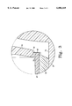
- FIG. 3 is an enlarged view of the portion of FIG. 2 which is encircled and indicated as FIG. 3.
- Track type tractor 10 which incorporates the features of the present invention therein.
- Track type tractor 10 includes a forward roller 16, a rear roller 18, and a midwheel assembly 20.
- Midwheel assembly 20 includes a number of outer wheel assemblies 30, a number of inner wheel assemblies 32, an axle 28, and a track assembly 12.
- Each outer wheel assembly 30 includes a hub 36 having (i) a body portion 50 having an axle cavity 40 defined therein and (ii) a hub plate 52 extending radially from body portion 50.
- Each outer wheel assembly 30 also includes a wheel 34 having (i) a wheel plate 58 secured to body portion 50 of hub 36 with a pair of bolts 38 and (ii) a ring member 60 secured to wheel plate 58 such that ring member 60 extends from wheel plate 58 toward hub plate 52 so that ring member 60, wheel plate 58, and hub plate 52 collectively define a wheel cavity 70.
- Each outer wheel assembly 30 further includes a rubber cover 62 secured to an outer surface 72 of ring member 60, a volume of oil 80 disposed in axle cavity 40, a collar assembly 45, and a pair of roller bearing assemblies 42 and 44.
- rubber cover 62 can be secured to outer surface 72 of ring member 60 using an appropriate adhesive.
- rubber cover has a circular shape and surrounds ring member 60.
- hub plate 52 has a disk like shape and a peripheral end segment 54 which encircles axle 28.
- Ring member 60 also has a peripheral end segment 68 which encircles axle 28.
- peripheral end segment 54 is spaced apart from peripheral end segment 68 so as to define an insulation space 78 therebetween.
- peripheral end segment 54 is close enough to peripheral end segment 68 such that, under extreme loads, ring member 60 can flex and contact hub plate 52. Allowing ring member 60 to flex and contact hub plate 52 under extreme loads increases the structural strength of outer wheel assembly 30.
- the distance between peripheral end segment 54 and peripheral end segment 68 is in the range of about 1.0 to 5.0 millimeters. More preferably, the distance between peripheral end segment 54 and peripheral end segment 68 is about 2.0 millimeters.
- axle 28 is positioned within axle cavity 40.
- Roller bearing assemblies 42 and 44 are disposed around axle 28 and positioned within axle cavity 40 such that wheel 34 and hub 36 can rotate relative to axle 28.
- Track assembly 12 includes (i) a carcass 26 having an upper surface 74 and a lower surface 76, (ii) a tread bar 22 extending from lower surface 76 of carcass 26, and (iii) a guide block 24 extending from upper surface 74 of carcass 26.
- Track assembly 12 is disposed around front roller 16 and rear roller 18 as shown in FIG. 1.
- track assembly 12 is positioned relative to inner wheel assembly 32 and outer wheel assembly 32 such that guide block 24 is interposed therebetween.
- Track assembly 12 is further positioned relative to wheel 34 and hub 36 of outer wheel assembly 32 such that (i) ring member 60 is positioned directly above upper surface 74 of carcass 26 and (ii) hub plate 52 is positioned adjacent to guide block 24.
- Positioning track assembly 12 relative to outer wheel assembly 30 in the above described manner interposes rubber cover 62 between upper surface 74 of carcass 26 and outer surface 72 of ring member 60.
- positioning track assembly 12 relative to outer wheel assembly 30 in the above described manner locates an annular guide block face 56 defined on hub plate 52 adjacent to guide block 24. (Note that that guide block face encircles axle 28.)
- Collar assembly 45 includes (i) a collar 48 disposed around axle 28 and (ii) a seal 46 disposed around collar 48 such that seal 46 is interposed between collar 48 and body portion 50 of hub 36. Collar assembly 45 is disposed around axle 28 and positioned within axle cavity 40 so as to prevent volume of oil 80 from exiting axle cavity 40.
- each inner wheel assembly 32 is constructed in a substantially identical manner as described above for each outer wheel assembly 30.
- Axle 28 is also positioned within an axle cavity 40 of each inner wheel assembly 32 such that the wheel and hub of inner wheel assembly 32 can rotate relative to axle 28.
- each inner wheel assembly 32 is positioned relative to track assembly 12 in a manner corresponding to that described above for each outer wheel assembly 30.
- track assembly 12 rotates around a path defined by forward roller 16 and rear roller 18.
- rubber cover 62 of each outer wheel assembly 30 contacts upper surface 74 of carcass 26 which causes outer wheel assembly 30 to rotates around a central axis 64 in a direction indicated by arrow 66 (see FIG. 2).
- Inner wheel assembly 32 is rotated in a substantially identical manner.
- guide block 24 periodically contacts guide block face 56 of hub plate 52.
- track assembly 12 moves relative to outer wheel assembly 30 such that guide block 24 comes into contact with guide block face 56 (see FIG. 2).
- Positioning guide block 24 in contact with guide block face 56 ensures that track assembly 12 remains disposed around forward roller 16 and rear roller 18.
- Positioning guide block 24 in contact with guide block face 56 as outer wheel assembly 30 rotates around central axis 64 and track assembly 12 rotates around a path defined by forward roller 16 and rear roller 18 causes hub plate 52 to heat up as a result of the friction between guide block face 56 and guide block 24. The heat generated by the aforementioned friction is conducted to body portion 50 and the volume oil 80 contained within axle cavity 40 via hub plate 52.
- Another advantage of the present invention is that none of the components of either outer wheel assembly 30 or inner wheel assembly 32 are welded together which decreases their manufacturing cost. Furthermore, wheel 34 can be easily removed from hub 36 by removing bolts 38 so as to gain access to wheel cavity 70 for maintenance purposes.
- outer wheel assemblies 30 and inner wheel assemblies 32 of the present invention require less machining as compared to other midwheel assembly designs. Specifically, only guide block face 56 requires machining. Therefore, the manufacturing cost of midwheel assembly 20 is less as compared to other midwheel assembly designs.
Abstract
Description
Claims (20)
Priority Applications (3)
| Application Number | Priority Date | Filing Date | Title |
|---|---|---|---|
| US09/196,044 US6086169A (en) | 1998-11-19 | 1998-11-19 | Midwheel assembly for a track type tractor |
| DE19948629A DE19948629A1 (en) | 1998-11-19 | 1999-10-08 | Central wheel arrangement for track-type tractor has hub with hub plate and wheel with wheel plate and ring member, defining hollow heel chamber for easier access |
| AU59465/99A AU749744B2 (en) | 1998-11-19 | 1999-11-16 | Midwheel assembly for a track type tractor |
Applications Claiming Priority (1)
| Application Number | Priority Date | Filing Date | Title |
|---|---|---|---|
| US09/196,044 US6086169A (en) | 1998-11-19 | 1998-11-19 | Midwheel assembly for a track type tractor |
Publications (1)
| Publication Number | Publication Date |
|---|---|
| US6086169A true US6086169A (en) | 2000-07-11 |
Family
ID=22723912
Family Applications (1)
| Application Number | Title | Priority Date | Filing Date |
|---|---|---|---|
| US09/196,044 Expired - Lifetime US6086169A (en) | 1998-11-19 | 1998-11-19 | Midwheel assembly for a track type tractor |
Country Status (3)
| Country | Link |
|---|---|
| US (1) | US6086169A (en) |
| AU (1) | AU749744B2 (en) |
| DE (1) | DE19948629A1 (en) |
Cited By (10)
| Publication number | Priority date | Publication date | Assignee | Title |
|---|---|---|---|---|
| US6206492B1 (en) * | 1999-07-20 | 2001-03-27 | Caterpillar Inc. | Mid-roller for endless track laying work machine |
| US6299264B1 (en) * | 1999-01-27 | 2001-10-09 | Caterpillar Inc. | Heat shielded mid-roller |
| US20050035655A1 (en) * | 2003-08-13 | 2005-02-17 | Clark Equipment Company | Track with offset drive lugs and drive wheel therefore |
| US20050056468A1 (en) * | 2003-09-17 | 2005-03-17 | Tucker Sno-Cat Corporation | Tracked vehicle with improved track drive unit |
| US20050173982A1 (en) * | 2004-01-13 | 2005-08-11 | Camoplast Inc. | Belt over mid-rollers |
| US20100270856A1 (en) * | 2008-02-13 | 2010-10-28 | Komatsu Ltd. | Crawler-type travel device and rotational wheel assembly |
| US20150314817A1 (en) * | 2014-04-01 | 2015-11-05 | Hutchinson Sa | Road Wheel |
| WO2015166302A1 (en) | 2014-04-29 | 2015-11-05 | B-K Medical Aps | Ultrasound imaging probe |
| CN105270498A (en) * | 2015-11-30 | 2016-01-27 | 玉林市川迪机器制造有限公司 | Excavator crawler-type guiding wheel |
| US9919751B1 (en) | 2015-11-09 | 2018-03-20 | Lyn A. Rosenboom | Track assembly |
Families Citing this family (1)
| Publication number | Priority date | Publication date | Assignee | Title |
|---|---|---|---|---|
| IT201600087275A1 (en) * | 2016-08-25 | 2018-02-25 | Cnh Ind Italia Spa | TRACK SYSTEM INCLUDING A SENSOR AND ITS VEHICLE |
Citations (17)
| Publication number | Priority date | Publication date | Assignee | Title |
|---|---|---|---|---|
| US34909A (en) * | 1862-04-08 | Improvement in harvester-rakes | ||
| US2791256A (en) * | 1953-11-16 | 1957-05-07 | Kelsey Hayes Co | Wheel and method of making the same |
| US2838344A (en) * | 1954-07-02 | 1958-06-10 | Porsche System Engineering Ltd | Bogie-wheel suspension for tracked vehicles |
| US3013843A (en) * | 1960-03-11 | 1961-12-19 | Gen Motors Corp | Vehicle suspension |
| US3540743A (en) * | 1968-02-26 | 1970-11-17 | Caterpillar Tractor Co | Inverted floating ring seal |
| US3567292A (en) * | 1969-02-19 | 1971-03-02 | Us Army | Sprocket engagement support wheel for an endless track |
| DE2733307A1 (en) * | 1977-07-20 | 1979-02-08 | Kronprinz Ag | Chain bearer roller for endless tracked vehicles - has soft steel wheel with hardened press fit rim and bonded rubber tyre |
| US4425008A (en) * | 1981-08-17 | 1984-01-10 | Motor Wheel Corporation | Wheel for a tracklaying vehicle |
| US4538860A (en) * | 1981-03-05 | 1985-09-03 | Gkn Technology Limited | Wear resistant wheel for track laying vehicle |
| US4838373A (en) * | 1988-06-30 | 1989-06-13 | Caterpillar Inc. | Suspension structure for a tracked vehicle |
| US4881609A (en) * | 1987-12-22 | 1989-11-21 | Caterpillar Inc. | Suspension mechanism for a track-type vehicle |
| US4923257A (en) * | 1989-04-13 | 1990-05-08 | Caterpillar Inc. | Belted vehicle suspension system |
| US4950030A (en) * | 1986-05-30 | 1990-08-21 | Motor Wheel Corporation | Wheel for a track laying vehicle |
| US4998783A (en) * | 1988-06-03 | 1991-03-12 | Diehl Gmbh | Track roller or guide roller for track-laying vehicles |
| US5022718A (en) * | 1990-08-31 | 1991-06-11 | Caterpillar Inc. | Idler wheel assembly |
| US5533587A (en) * | 1993-10-26 | 1996-07-09 | Byron Enterprises, Inc. | Track vehicles and power drive apparatus for motivating tracked vehicles |
| US6012784A (en) * | 1998-01-30 | 2000-01-11 | Caterpillar Inc. | Impact reducing idler wheel for a track-driven machine |
-
1998
- 1998-11-19 US US09/196,044 patent/US6086169A/en not_active Expired - Lifetime
-
1999
- 1999-10-08 DE DE19948629A patent/DE19948629A1/en not_active Withdrawn
- 1999-11-16 AU AU59465/99A patent/AU749744B2/en not_active Ceased
Patent Citations (17)
| Publication number | Priority date | Publication date | Assignee | Title |
|---|---|---|---|---|
| US34909A (en) * | 1862-04-08 | Improvement in harvester-rakes | ||
| US2791256A (en) * | 1953-11-16 | 1957-05-07 | Kelsey Hayes Co | Wheel and method of making the same |
| US2838344A (en) * | 1954-07-02 | 1958-06-10 | Porsche System Engineering Ltd | Bogie-wheel suspension for tracked vehicles |
| US3013843A (en) * | 1960-03-11 | 1961-12-19 | Gen Motors Corp | Vehicle suspension |
| US3540743A (en) * | 1968-02-26 | 1970-11-17 | Caterpillar Tractor Co | Inverted floating ring seal |
| US3567292A (en) * | 1969-02-19 | 1971-03-02 | Us Army | Sprocket engagement support wheel for an endless track |
| DE2733307A1 (en) * | 1977-07-20 | 1979-02-08 | Kronprinz Ag | Chain bearer roller for endless tracked vehicles - has soft steel wheel with hardened press fit rim and bonded rubber tyre |
| US4538860A (en) * | 1981-03-05 | 1985-09-03 | Gkn Technology Limited | Wear resistant wheel for track laying vehicle |
| US4425008A (en) * | 1981-08-17 | 1984-01-10 | Motor Wheel Corporation | Wheel for a tracklaying vehicle |
| US4950030A (en) * | 1986-05-30 | 1990-08-21 | Motor Wheel Corporation | Wheel for a track laying vehicle |
| US4881609A (en) * | 1987-12-22 | 1989-11-21 | Caterpillar Inc. | Suspension mechanism for a track-type vehicle |
| US4998783A (en) * | 1988-06-03 | 1991-03-12 | Diehl Gmbh | Track roller or guide roller for track-laying vehicles |
| US4838373A (en) * | 1988-06-30 | 1989-06-13 | Caterpillar Inc. | Suspension structure for a tracked vehicle |
| US4923257A (en) * | 1989-04-13 | 1990-05-08 | Caterpillar Inc. | Belted vehicle suspension system |
| US5022718A (en) * | 1990-08-31 | 1991-06-11 | Caterpillar Inc. | Idler wheel assembly |
| US5533587A (en) * | 1993-10-26 | 1996-07-09 | Byron Enterprises, Inc. | Track vehicles and power drive apparatus for motivating tracked vehicles |
| US6012784A (en) * | 1998-01-30 | 2000-01-11 | Caterpillar Inc. | Impact reducing idler wheel for a track-driven machine |
Cited By (16)
| Publication number | Priority date | Publication date | Assignee | Title |
|---|---|---|---|---|
| US6299264B1 (en) * | 1999-01-27 | 2001-10-09 | Caterpillar Inc. | Heat shielded mid-roller |
| US6206492B1 (en) * | 1999-07-20 | 2001-03-27 | Caterpillar Inc. | Mid-roller for endless track laying work machine |
| US20050035655A1 (en) * | 2003-08-13 | 2005-02-17 | Clark Equipment Company | Track with offset drive lugs and drive wheel therefore |
| US7201242B2 (en) * | 2003-09-17 | 2007-04-10 | Tucker Sno-Cat Corporation | Tracked vehicle with improved track drive unit |
| US20050056468A1 (en) * | 2003-09-17 | 2005-03-17 | Tucker Sno-Cat Corporation | Tracked vehicle with improved track drive unit |
| US20050072607A1 (en) * | 2003-09-17 | 2005-04-07 | Tucker Sno-Cat Corporation | Tracked vehicle with improved track drive unit |
| US6983812B2 (en) * | 2003-09-17 | 2006-01-10 | Tucker Sno-Cat Corporation | Tracked vehicle with improved track drive unit |
| US7252347B2 (en) | 2004-01-13 | 2007-08-07 | Camoplast Inc. | Belt over mid-rollers |
| US20050173982A1 (en) * | 2004-01-13 | 2005-08-11 | Camoplast Inc. | Belt over mid-rollers |
| US20100270856A1 (en) * | 2008-02-13 | 2010-10-28 | Komatsu Ltd. | Crawler-type travel device and rotational wheel assembly |
| US8366212B2 (en) * | 2008-02-13 | 2013-02-05 | Komatsu Ltd. | Crawler-type travel device and rotational wheel assembly |
| US20150314817A1 (en) * | 2014-04-01 | 2015-11-05 | Hutchinson Sa | Road Wheel |
| US9663163B2 (en) * | 2014-04-01 | 2017-05-30 | Hutchinson Sa | Road wheel |
| WO2015166302A1 (en) | 2014-04-29 | 2015-11-05 | B-K Medical Aps | Ultrasound imaging probe |
| US9919751B1 (en) | 2015-11-09 | 2018-03-20 | Lyn A. Rosenboom | Track assembly |
| CN105270498A (en) * | 2015-11-30 | 2016-01-27 | 玉林市川迪机器制造有限公司 | Excavator crawler-type guiding wheel |
Also Published As
| Publication number | Publication date |
|---|---|
| AU5946599A (en) | 2000-05-25 |
| DE19948629A1 (en) | 2000-05-25 |
| AU749744B2 (en) | 2002-07-04 |
Similar Documents
| Publication | Publication Date | Title |
|---|---|---|
| US6086169A (en) | Midwheel assembly for a track type tractor | |
| US6012784A (en) | Impact reducing idler wheel for a track-driven machine | |
| CN101025202B (en) | Bearing device for drive wheel | |
| US6733093B2 (en) | Split wheel and method for installing endless track | |
| US4235271A (en) | Tire sidewall protector shield assembly | |
| US11273668B2 (en) | Omnidirectional wheel | |
| CA2249256A1 (en) | Tracked vehicle with improved guide wheel assembly | |
| JP2001354171A (en) | Noise-reduced transmission idler wheel for crawler type vehicle | |
| US6299264B1 (en) | Heat shielded mid-roller | |
| US6540630B1 (en) | Reduced sound transmitting sprocket for track-type machines | |
| US6173821B1 (en) | Disk brake protector for a disk brake of a motor vehicle wheel with perforated rim dish | |
| CA2463399A1 (en) | Wheel assembly for a tracked vehicle | |
| EP1174285B1 (en) | A varying-track wheel with devices for mutual-positioning of the rim and disc | |
| JP5031154B2 (en) | Guide device for endless track type work machine | |
| JP2001354172A (en) | Carrier roller assembly for base carrier assembly of work machine having roller shaft equipped with integrally formed thrust surface | |
| JPH02286476A (en) | Combined roller guard for rubber and iron crawler | |
| JP2731086B2 (en) | Seal part for guide wheels of crawler traveling device | |
| US4018298A (en) | Wheel assembly with slip clutch | |
| JP2001099199A (en) | Drum brake seal structure of unlevelled ground running wheel | |
| JPH09156309A (en) | Segment to install wheel or crawler belt | |
| JP7362513B2 (en) | work vehicle | |
| US1921537A (en) | Cushion cleat wheel | |
| EP1542898B1 (en) | Split wheel and method for installing endless track | |
| US11572113B2 (en) | Fabricated track roller rim assembly | |
| KR910001547Y1 (en) | Roller for endless-track vehicles |
Legal Events
| Date | Code | Title | Description |
|---|---|---|---|
| AS | Assignment |
Owner name: CATERPILLAR, INC., ILLINOIS Free format text: ASSIGNMENT OF ASSIGNORS INTEREST;ASSIGNOR:KEEHNER, DANIEL M.;REEL/FRAME:009400/0512 Effective date: 19981116 |
|
| STCF | Information on status: patent grant |
Free format text: PATENTED CASE |
|
| FPAY | Fee payment |
Year of fee payment: 4 |
|
| AS | Assignment |
Owner name: CAMOPLAST ROCKLAND LTD., NEW YORK Free format text: ASSIGNMENT OF ASSIGNORS INTEREST;ASSIGNOR:CATERPILLAR INC.;REEL/FRAME:015452/0599 Effective date: 20031030 |
|
| FEPP | Fee payment procedure |
Free format text: PAYOR NUMBER ASSIGNED (ORIGINAL EVENT CODE: ASPN); ENTITY STATUS OF PATENT OWNER: LARGE ENTITY |
|
| FPAY | Fee payment |
Year of fee payment: 8 |
|
| FEPP | Fee payment procedure |
Free format text: PAYER NUMBER DE-ASSIGNED (ORIGINAL EVENT CODE: RMPN); ENTITY STATUS OF PATENT OWNER: LARGE ENTITY Free format text: PAYOR NUMBER ASSIGNED (ORIGINAL EVENT CODE: ASPN); ENTITY STATUS OF PATENT OWNER: LARGE ENTITY |
|
| AS | Assignment |
Owner name: CAMOPLAST INC., CANADA Free format text: ASSIGNMENT OF ASSIGNORS INTEREST;ASSIGNOR:CAMOPLAST ROCKLAND LTD.;REEL/FRAME:025217/0915 Effective date: 20101029 |
|
| AS | Assignment |
Owner name: CAMOPLAST SOLIDEAL INC., CANADA Free format text: CERTIFICATE OF AMENDMENT;ASSIGNOR:CAMOPLAST INC.;REEL/FRAME:026466/0978 Effective date: 20101102 |
|
| FPAY | Fee payment |
Year of fee payment: 12 |