US6085387A - Hinge device - Google Patents
Hinge device Download PDFInfo
- Publication number
- US6085387A US6085387A US09/149,983 US14998398A US6085387A US 6085387 A US6085387 A US 6085387A US 14998398 A US14998398 A US 14998398A US 6085387 A US6085387 A US 6085387A
- Authority
- US
- United States
- Prior art keywords
- axis
- cam
- hinge
- along
- cam follower
- Prior art date
- Legal status (The legal status is an assumption and is not a legal conclusion. Google has not performed a legal analysis and makes no representation as to the accuracy of the status listed.)
- Expired - Fee Related
Links
Images


Classifications
-
- H—ELECTRICITY
- H04—ELECTRIC COMMUNICATION TECHNIQUE
- H04B—TRANSMISSION
- H04B1/00—Details of transmission systems, not covered by a single one of groups H04B3/00 - H04B13/00; Details of transmission systems not characterised by the medium used for transmission
- H04B1/38—Transceivers, i.e. devices in which transmitter and receiver form a structural unit and in which at least one part is used for functions of transmitting and receiving
-
- H—ELECTRICITY
- H04—ELECTRIC COMMUNICATION TECHNIQUE
- H04M—TELEPHONIC COMMUNICATION
- H04M1/00—Substation equipment, e.g. for use by subscribers
- H04M1/02—Constructional features of telephone sets
- H04M1/0202—Portable telephone sets, e.g. cordless phones, mobile phones or bar type handsets
- H04M1/0206—Portable telephones comprising a plurality of mechanically joined movable body parts, e.g. hinged housings
- H04M1/0208—Portable telephones comprising a plurality of mechanically joined movable body parts, e.g. hinged housings characterized by the relative motions of the body parts
- H04M1/0214—Foldable telephones, i.e. with body parts pivoting to an open position around an axis parallel to the plane they define in closed position
- H04M1/0216—Foldable in one direction, i.e. using a one degree of freedom hinge
-
- E—FIXED CONSTRUCTIONS
- E05—LOCKS; KEYS; WINDOW OR DOOR FITTINGS; SAFES
- E05D—HINGES OR SUSPENSION DEVICES FOR DOORS, WINDOWS OR WINGS
- E05D11/00—Additional features or accessories of hinges
- E05D11/10—Devices for preventing movement between relatively-movable hinge parts
- E05D11/1028—Devices for preventing movement between relatively-movable hinge parts for maintaining the hinge in two or more positions, e.g. intermediate or fully open
- E05D11/1078—Devices for preventing movement between relatively-movable hinge parts for maintaining the hinge in two or more positions, e.g. intermediate or fully open the maintaining means acting parallel to the pivot
-
- E—FIXED CONSTRUCTIONS
- E05—LOCKS; KEYS; WINDOW OR DOOR FITTINGS; SAFES
- E05Y—INDEXING SCHEME ASSOCIATED WITH SUBCLASSES E05D AND E05F, RELATING TO CONSTRUCTION ELEMENTS, ELECTRIC CONTROL, POWER SUPPLY, POWER SIGNAL OR TRANSMISSION, USER INTERFACES, MOUNTING OR COUPLING, DETAILS, ACCESSORIES, AUXILIARY OPERATIONS NOT OTHERWISE PROVIDED FOR, APPLICATION THEREOF
- E05Y2999/00—Subject-matter not otherwise provided for in this subclass
Definitions
- the present invention relates generally to the field of a portable radiotelephone, and more particularly to a hinge device of coupling a button cover and a body of the radiotelephone.
- buttons is equipped on the top surface of a portable radiotelephone.
- a button cover covering the buttons is prepared to prevent the buttons of the radiotelephone from being accidentally operated by the unintentional exertion of force.
- the button cover may rotate between a first position covering the buttons and a second position allowing a user to push one of the buttons, which is known in the art.
- the button cover structure of the portable radiotelephone should be designed for a user to use conveniently.
- a hinge device is provided to make the button cover move automatically toward either the first or second position.
- the modulated hinge device is required to have the structure for holding moving parts of the hinge, such as a cam member, a cam follower and a spring.
- the size and the number of parts of the holding structure should be reduced.
- the relative motion between the cam member and the cam follower of the hinge is required to be smoothly done. Additionally, when the cam follower slides along the cam surface, it should be guided stably.
- a hinge comprising:
- a can having a partially closed end, an opened end and a protrusion which can be bended so as to at least partially close the opened end;
- one of the first member and the second member having a cam portion, the cam portion including at least a peak and two valleys separated by the peak and slopes connecting the peak and the valleys;
- a hinge comprising:
- a can having a partially closed end and an opened end
- one of the first member and the second member having a cam portion, the cam portion including at least a peak and two valleys separated by the peak and slopes connecting the peak and the valleys, the cam portion having a cam surface formed on one side of the cam portion so that the intersection of the cam surface and a plane including a rotating axis of the hinge is maintained to be substantially same along the cam surface;
- a closer at least partially closing the opened end of the can.
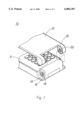
- FIG. 1 is a partially cutaway exploded, perspective view of a portable radiotelephone showing that a hinge is assembled with a main body of the radiotelephone and a button cover is disassembled;
- FIG. 2 is a partially cutaway exploded, perspective view of a upper housing of the portable radiotelephone and the hinge;
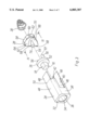
- FIG. 3 is a exploded view of the hinge in accordance with the present invention.
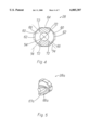
- FIG. 4 is a sectional view taken along the line IV--IV of FIG. 3;
- FIG. 5 is a perspective view of another second member of the hinge in accordance with the present invention.
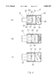
- FIGS. 6A, 6B and 6C are sectional views of the hinge showing the operation of the hinge of FIG. 3;
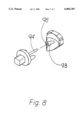
- FIG. 8 is a exploded, perspective view of a first and second member of an alternative hinge in accordance with the present invention.
- a portable radiotelephone 10 has a button cover 12 mounted on an upper housing 11 thereof.
- the radiotelephone 10 has a hinge 14 to couple the upper housing 11 and the button cover 12.
- the hinge 14 has a rotatable shaft 16 extended outwardly.
- the shaft 16 has engaging surfaces 18.
- the button cover 12 has a bushing 19 engaging with the shaft 16.
- the button cover has a shaft, while the hinge has a bushing.
- the hinge 14 is mounted into a cavity 22 of the upper housing 11.
- a hole 23 for inserting the hinge 14 is prepared on a sidewall of the housing 11.
- the hinge 14 is inserted through the hole 23.
- FIG. 2 show that the hinge 14 is inserted through the hole 23, the hinge 14 may be inserted from the above of the housing 11 shown in FIG. 2.
- the hinge 14 in accordance with an embodiment of the present invention has a can 24, a first hinge member 26, a second hinge member 28 and an elastic member 30.
- the first member 26, second member 28 and elastic member 30 are in turn accommodated in the can 24.
- the can 24 has an elongated octagonal shape.
- a longitudinal center line of the can 24 defines a rotating axis 54 of the hinge 14.
- One end 32 of the can 24 has a wall 36 and a hole 34 for the shaft 16 of the hinge 14 to extend therethrough.
- the other end 42 opposing to the end 32 is opened.
- Sidewall 38 of the can 24 has a groove 40 which is axially extended. Also, sidewall opposite to the sidewall 38 has a same kind of groove which is opened at the opened end 42.
- Retaining Protrusions 48 extending from the end 42 are provided at sidewall 44 and 46.
- the protrusions 48 can be bent along bending lines 50 so as to at least partially cover the opened end 42. It is preferable that the can 24 is formed of metal such as brass and is manufactured by a method of drawing.
- the first member 26 has a disk-shaped body 52 and a shaft 16 which is projected from the body 52 along the axis 54.
- the shaft 16 has the engaging surfaces 18 for engaging with the button cover 12 (see FIG. 1).
- two protrusions 56 are projected from the body 52 and extended along the direction parallel to the axis 54.
- the protrusions 56 are diametrically positioned around the rotating axis 54 of the hinge 14.
- the protrusions 56 function as a cam following portion or cam follower.
- the cam following portion or cam follower means a portion following a cam surface described below.
- Each protrusion 56 has a cylindrical body and a hemispherical end.
- the configuration of the protrusion 56 is not limited to the above. It can be understood in the art that the protrusion 56 may have a body of a polygonal pillar.
- the first member 26 is inserted through the opened end 42 of the can 24.
- the first member 26 can rotate around the rotating axis 54 in the can 24.
- the shaft 16 of the first member 26 is extended through the hole 34 of the can 24.
- the hinge 14 is mounted on the upper housing 11 of the radiotelephone 10, the shaft 16 of the first member 26 is projected outwardly (see FIG. 1 and FIG. 2).
- the second member 28 has a body 58 of an octagonal plate corresponding to the inside of housing 24. Opposing tabs 62 are projected from opposing sides of the body 58.
- a cylindrical cam portion 64 is formed on an end of the body 58.
- the cam portion 64 has a slanted cam surface 66 formed on an end of the cam portion 64.
- the cam portion 64 has two peaks 68 and two valleys 70. The peaks 68 are arranged diametrically and the valleys 70 are separated by the peaks 68 and arranged diametrically.
- the cam surface 66 is continuous to connect the peaks 68 and the valleys 70. As shown in FIG. 4, when the cam surface 66 of the second member 28 is intersected by a plane perpendicular to the axis 54, the intersection lines 72 and 74 are substantially straight and the extending line of each line 72 or 74 pass through the rotating axis 54.
- FIG. 5 shows an alternative embodiment of the second member.
- a groove 67a is formed on and along a cam surface 66a of a second member 28a.
- the ends 57 are guided by the groove 67a.
- the intersection of the plane and the cam surface 66a includes two straight lines and a curved line between the straight lines.
- the cam portion may be configured so that the intersection has only a concave curve.
- the second member 28 has a cylindrical guide column 76 extended along the axis 54 so as to guide the relative motion between the first member 26 and the second member 28. It is preferable that the diameter of the column 76 is slightly less than a gap distance between the protrusions 56 of the first member 26.
- the second member 28 is inserted through the opened end of the can 24.
- the cam surface 66 opposes to the protrusions 56 of the first member 26.
- the body 58 of the second member 28 is snugly inserted into the can 24.
- the tabs 62 are also inserted into the grooves 40 of the can 24.
- the elastic member 30 exerts the elastic force on the second member 28 to push the second member 28 toward the first member 26. It is preferable that the elastic member 30 is a conical coil spring so as to minimize its length when it is compressed.
- the opened end 42 of the can 24 is at least partially covered by way of bending the protrusions 48 of the can 24 along the bending lines 50 (see FIGS. 2 and 6).
- FIGS. 6a, 6b and 6c the operation of the hinge 14 in accordance with the present invention will be explained below.
- FIG. 6a shows a state of the hinge 14, for example, that the button cover 12 covers the buttons of the radiotelephone 10.
- the hemispherical ends 57 of the protrusions 56 are positioned on the slope surface between the peaks 68 and valleys 70 of the cam portion 64.
- the first member 26 tends to rotate by means of a interaction between the ends of the protrusions 56 and the slanted surface of the cam surface 66 of the second member 28 on which the elastic member 30 exert the force. This makes the button cover 12 offset toward the body of the radiotelephone 10 so as to keep the button cover 12 closed.
- FIG. 6b shows a state that the hemispherical ends 57 of the protrusions 56 reach the peaks 68.
- the button cover 12 is positioned a certain point between the first position and the second position, which will be referred to as a third position hereinbelow.
- FIG. 6c shows a state that the button cover 12 arrives at the second position, in which the button cover 12 is opened.
- button cover 12 If the button cover 12 is freed at a position between the first position and the third position, it rotates toward the first position. In the other hand, if the button cover 12 is freed at a position between the second and the third position, it rotates toward the second position.
- FIG. 7 shows a first member 80 and a second member 82 of the hinge in accordance with a further alternative embodiment of the present invention.
- the body and the shaft of the first member 80 is similar to those of the first member 26 described in the above.
- the first member 80 has a cylindrical guide column 84 which is projected from the body and extended along the rotating axis.
- the first member 80 has opposing square protrusions 86 defining a cam follower. Each protrusion 86 extends axially and is diametrically positioned around the cylindrical guide column 84.
- Each protrusion 86 has an end 88.
- the shape of the intersection line of the end 88 and a plane parallel to the axis 54 is semicircular.
- This configuration offers line contact between the end 88 of the first member 80 and the cam surface of the second member 82.
- the protrusions 86 is shown to be integrated with the guide column 84 in FIG. 7, the protrusions 86 may be spaced from the guide column 84.
- the body and the cam portion of the second member 82 are similar to those of the second member 28 described in the above embodiment.
- the second member 82 has a guide groove or hole 92.
- the guide column 84 is slidably inserted into the guide hole 92.
- the guide column 84 and the guide hole 92 guide the relative motion between the cam surface and the cam follower.
- the first member of the present invention has an elongated, cylindrical guide pin 94 and the second member has a guide column or boss 98 as in the second member shown in FIG. 3.
- a guide hole 96 is formed on the boss.
- the guide pin 94 and the guide hole 96 extend axially.
- the guide pin 94 is slidably inserted into the guide hole 96.
- the guide pin 94 and the guide hole 96 ensure the good guidance of the relative motion between the first and second members and prevent the second member from being slanted.
- the can may have circular or rectangular shape. Then the body of the second member may have a shape corresponding to the can.
- slope angles of the potions of the cam surface which connect the peaks and the valleys are described to be same in the above embodiments. However, the angles of the surfaces connecting one of the peaks with two opposing valleys may vary. In this case, a line connecting the opposing peaks and a line connecting the opposing valleys are not perpendicular to each other.
- the first member have a cam follower and the second member has a cam portion in the above embodiment, the first member may have a cam surface and the second member may have a cam follower.
- the can may be constructed of a thermoplastic resin and a cap may be provided to cover the opened end of the can.
- the can may be configured to have a body of thermoplastic resin and a pair of retaining protrusions of metal by way of the insert molding.
Landscapes
- Engineering & Computer Science (AREA)
- Signal Processing (AREA)
- Computer Networks & Wireless Communication (AREA)
- Pivots And Pivotal Connections (AREA)
- Telephone Set Structure (AREA)
Abstract
Description
Claims (25)
Applications Claiming Priority (2)
| Application Number | Priority Date | Filing Date | Title |
|---|---|---|---|
| KR1019980017775A KR100266516B1 (en) | 1998-05-18 | 1998-05-18 | Hinge device |
| KR98-17775 | 1998-05-18 |
Publications (1)
| Publication Number | Publication Date |
|---|---|
| US6085387A true US6085387A (en) | 2000-07-11 |
Family
ID=19537431
Family Applications (1)
| Application Number | Title | Priority Date | Filing Date |
|---|---|---|---|
| US09/149,983 Expired - Fee Related US6085387A (en) | 1998-05-18 | 1998-09-09 | Hinge device |
Country Status (2)
| Country | Link |
|---|---|
| US (1) | US6085387A (en) |
| KR (1) | KR100266516B1 (en) |
Cited By (47)
| Publication number | Priority date | Publication date | Assignee | Title |
|---|---|---|---|---|
| US6292980B1 (en) * | 1998-05-26 | 2001-09-25 | Samsung Electronics Co., Ltc. | Hinge mechanism of portable phone |
| US20020086700A1 (en) * | 2000-12-30 | 2002-07-04 | Samsung Electronics Co., Ltd. | Hinge module for portable radio terminal |
| DE10037696C2 (en) * | 1999-08-06 | 2002-11-21 | Sugatsune Kogyo Co | hinge assembly |
| US20030009851A1 (en) * | 2000-09-29 | 2003-01-16 | Kazuyoshi Oshima | Hinge device |
| US20030009852A1 (en) * | 2000-09-29 | 2003-01-16 | Kazuyoshi Oshima | Hinge device |
| US20030040330A1 (en) * | 2001-08-23 | 2003-02-27 | Samsung Electronics Co., Ltd. | Foldable wireless terminal |
| US20040091101A1 (en) * | 2002-11-12 | 2004-05-13 | Sung-Sun Park | Hinge device for portable wireless terminal |
| US6745436B2 (en) * | 2001-05-31 | 2004-06-08 | Samsung Electronics Co., Ltd. | Hinge apparatus for a portable radiophone having a multi-angled hinge cam |
| US20040145870A1 (en) * | 2003-01-08 | 2004-07-29 | Katsuichi Minami | Opening and closing device |
| US20040203497A1 (en) * | 2002-07-02 | 2004-10-14 | Samsung Electro-Mechanics Co., Ltd. | Auto folder type mobile phone |
| US20040211036A1 (en) * | 2003-04-25 | 2004-10-28 | Jun-Kyu Park | Rotation-stop mechanism for folder of portable wireless terminal |
| US20040261224A1 (en) * | 2003-05-23 | 2004-12-30 | Li Chang Zhi | Hinge assembly |
| US20040261223A1 (en) * | 2003-06-06 | 2004-12-30 | Xiaozhou Wang | Hinge assembly |
| US20050155182A1 (en) * | 2004-01-20 | 2005-07-21 | Young-Soo Han | Hinge device |
| US20050202687A1 (en) * | 2004-03-12 | 2005-09-15 | Samsung Electronics Co., Ltd. | Swing hinge device of portable terminal |
| US20050225093A1 (en) * | 2004-04-09 | 2005-10-13 | Fih Co., Ltd | Automatic opening and closing hinge assembly for portable electronic devices |
| US20050236869A1 (en) * | 2004-04-09 | 2005-10-27 | Sung-Hyun Ka | Portable apparatus having two rotatable and foldable units and hinge device used for the same |
| US20060005356A1 (en) * | 2002-12-25 | 2006-01-12 | Nokia Corporation | Hinge device having angle hold function and folding electronic appliance using same |
| US20060045261A1 (en) * | 2004-08-27 | 2006-03-02 | Fih Co., Ltd | Hinge assembly for foldable electronic device |
| US20060101618A1 (en) * | 2004-11-12 | 2006-05-18 | Katsuichi Minami | Opening and closing device |
| US20060112517A1 (en) * | 2004-11-27 | 2006-06-01 | Hon Hai Precision Industry Co., Ltd | Hinge assembly for foldable electronic device |
| US20060117529A1 (en) * | 2004-12-03 | 2006-06-08 | Fih Co.,Ltd | Hinge assembly with lubricant storing receptacle |
| US20060123596A1 (en) * | 2004-12-09 | 2006-06-15 | Fih Co., Ltd | Hinge assembly for a foldable electronic device |
| US20060135199A1 (en) * | 2004-12-08 | 2006-06-22 | Lumberg Connect Gmbh & Co. Kg | Position-holding pivot/slide mechanism for cell phone |
| US7150072B2 (en) | 2003-05-30 | 2006-12-19 | Hon Hai Precision Ind. Co., Ltd. | Hinge assembly |
| US20070054636A1 (en) * | 2005-09-02 | 2007-03-08 | Lg Electronics Inc. | Mobile communication terminal having opening mechanism |
| US20070101541A1 (en) * | 2005-11-04 | 2007-05-10 | Shenzhen Futaihong Precision Industrial Co., Ltd. | Hinge assembly for portable electronic devices |
| US20070212162A1 (en) * | 2006-03-08 | 2007-09-13 | Scott Schank | Shearing-force mechanism with cross-linked thermoplastic |
| US20080047103A1 (en) * | 2006-08-22 | 2008-02-28 | Samsung Electronics Co., Ltd. | Hinge structure and a mobile communication terminal therewith |
| EP1782498A4 (en) * | 2004-04-28 | 2008-04-16 | Elcoteq Network Oyj | Mobile communications station |
| US20080136297A1 (en) * | 2006-10-05 | 2008-06-12 | Shan-Ping Huang | Hinge with buffer function |
| US20080274774A1 (en) * | 2007-05-03 | 2008-11-06 | Chang Soo Kim | Multi-step hinge and portable terminal having same |
| US20090158555A1 (en) * | 2007-12-21 | 2009-06-25 | Chi Mei Communication Systems, Inc. | Hinge assembly and foldable electronic device using the same |
| US20090300882A1 (en) * | 2006-06-30 | 2009-12-10 | Yoshitaka Hayashi | Hinge Device and Electronic Apparatus Using The Hinge Device |
| US20090320239A1 (en) * | 2008-06-26 | 2009-12-31 | Nokia Corporation | Apparatus for fold hinge assemblies for electronic devices and associated methods |
| US20100083468A1 (en) * | 2008-10-02 | 2010-04-08 | Shu-Mu Lin | Hinge and a Lamp with the Hinge |
| US20100291978A1 (en) * | 2007-06-12 | 2010-11-18 | Laird Technologies Korea Yh | Step hinge for portable communication terminals |
| CN101338785B (en) * | 2007-07-06 | 2010-12-01 | 深圳富泰宏精密工业有限公司 | Hinge structure and portable electronic device applying same |
| US20110235253A1 (en) * | 2009-09-29 | 2011-09-29 | Sierra Wireless, Inc. | Peripheral device with limited relative angular movement |
| US20120030905A1 (en) * | 2010-08-06 | 2012-02-09 | Fih (Hong Kong) Limited | Hinge assembly for foldable electronic device |
| US20120030904A1 (en) * | 2010-08-06 | 2012-02-09 | Fih (Hong Kong) Limited | Hinge assembly for foldable electronic device |
| US20120096676A1 (en) * | 2010-10-25 | 2012-04-26 | Fih (Hong Kong) Limited | Hinge assembly for foldable electronic device |
| US8523476B2 (en) | 2010-06-01 | 2013-09-03 | Reell Precision Manufacturing Corporation | Positioning and damper device using shear force from cyclic differential compressive strain of a cross-linked thermoplastic |
| US8959717B2 (en) | 2012-03-12 | 2015-02-24 | Reell Precision Manufacturing Corporation | Circumferential strain rotary detent |
| US20150145397A1 (en) * | 2013-11-26 | 2015-05-28 | Lg Electronics Inc. | Home appliance |
| EP3473904A1 (en) * | 2017-10-20 | 2019-04-24 | Siemens Schweiz AG | Valve actuator |
| CN116607858A (en) * | 2023-05-29 | 2023-08-18 | 泉州巨晖电子有限公司 | Door opener |
Families Citing this family (10)
| Publication number | Priority date | Publication date | Assignee | Title |
|---|---|---|---|---|
| KR100534537B1 (en) * | 1998-07-27 | 2006-03-20 | 피닉스코리아 주식회사 | Hinges for cordless telephones, manufacturing method and hinge manufacturing apparatus |
| JP2001355371A (en) * | 2000-06-14 | 2001-12-26 | Kato Electrical Mach Co Ltd | Miniaturized hinge device |
| JP2002039161A (en) * | 2000-07-31 | 2002-02-06 | Nifco Inc | Hinge unit and hinge structure |
| KR200241123Y1 (en) * | 2001-04-25 | 2001-10-12 | 원종림 | Apparatus For Opening and Closing The Cover of Mobile Communication Terminal |
| KR20030013567A (en) * | 2001-08-08 | 2003-02-15 | 삼성전자주식회사 | Hinge device with damping function for folder type mobile phone |
| KR100421260B1 (en) * | 2001-11-03 | 2004-03-09 | 장명택 | Hinge for kimchi-refrigerator |
| KR100451853B1 (en) * | 2002-05-28 | 2004-10-08 | 피닉스코리아 주식회사 | Hinge device |
| JP2004044743A (en) * | 2002-07-15 | 2004-02-12 | Kato Electrical Mach Co Ltd | Hinge for portable equipment |
| JP2006233998A (en) * | 2005-02-22 | 2006-09-07 | Kato Electrical Mach Co Ltd | Hinge unit of portable device and mobile phone |
| KR200464513Y1 (en) * | 2010-09-17 | 2013-01-08 | 주식회사 제호 | Damping hinge and container including the same |
Citations (29)
| Publication number | Priority date | Publication date | Assignee | Title |
|---|---|---|---|---|
| US4897873A (en) * | 1988-11-04 | 1990-01-30 | Motorola, Inc. | Multipurpose hinge apparatus for foldable telephones |
| WO1992017974A1 (en) * | 1991-03-28 | 1992-10-15 | Motorola, Inc. | Hinge apparatus for foldable radiotelephones |
| WO1992017973A1 (en) * | 1991-03-28 | 1992-10-15 | Motorola, Inc. | Multiposition detenting hinge apparatus |
| US5259019A (en) * | 1991-04-08 | 1993-11-02 | Texas Instruments Incorporated | Apparatus providing for a curved device with hinged cover |
| KR940025244A (en) * | 1993-04-28 | 1994-11-19 | 김광호 | Button cover switchgear on the phone |
| KR940027373A (en) * | 1993-05-31 | 1994-12-10 | 김광호 | Flip folding device of portable telephone |
| KR940027375A (en) * | 1993-05-31 | 1994-12-10 | 김광호 | Flip folding device of cordless phone |
| KR950003838A (en) * | 1993-07-28 | 1995-02-17 | 조용현 | Top open and close T.M. cell |
| KR950016135A (en) * | 1993-11-29 | 1995-06-17 | 김광호 | Flip folding device of cordless phone |
| KR950028895A (en) * | 1994-04-14 | 1995-11-22 | 오세중 | Coating equipment of polyethylene film for vinyl house and its articles |
| KR960003356A (en) * | 1994-06-09 | 1996-01-26 | 이헌조 | Projection TV's Low Light Control and Adjustment Method |
| JPH0865369A (en) * | 1994-08-24 | 1996-03-08 | Nifco Inc | Hinge member |
| KR960009192A (en) * | 1994-08-25 | 1996-03-22 | 문정환 | Manufacturing method of DRAM cell |
| KR960006945A (en) * | 1994-08-11 | 1996-03-22 | 김상웅 | Surgical suture coating composition and suture using the same |
| KR960020217A (en) * | 1994-11-15 | 1996-06-17 | 가토 지아키 | Switchgear of a mobile phone |
| KR960034654A (en) * | 1995-03-13 | 1996-10-24 | 카토 유이치 | Hinge device |
| KR960035780A (en) * | 1995-03-15 | 1996-10-28 | 우에시마 세이스케 | Method for manufacturing semiconductor device |
| KR970003514A (en) * | 1995-06-30 | 1997-01-28 | 김주용 | Method for manufacturing contact hole of semiconductor device |
| KR970009071A (en) * | 1995-07-20 | 1997-02-24 | 김광호 | Button cover switchgear on the phone |
| KR970015497A (en) * | 1995-09-28 | 1997-04-28 | 엘리 웨이스 | Solid electrostatic discharge shoes |
| KR970019181A (en) * | 1995-09-20 | 1997-04-30 | 구자홍 | Switchgear of cell phone flip |
| US5628089A (en) * | 1995-05-18 | 1997-05-13 | Motorola, Inc. | Radiotelephone having a self contained hinge |
| US5651063A (en) * | 1994-08-23 | 1997-07-22 | Samsung Electronics Co., Ltd. | Hinge apparatus for a foldable telephone |
| KR970047849A (en) * | 1995-12-13 | 1997-07-26 | 김태구 | Vehicle door glass channel measuring device |
| US5661797A (en) * | 1995-11-01 | 1997-08-26 | Nokia Mobile Phones Ltd. | Hinge mechanism for cellular transceiver housing |
| KR970064422A (en) * | 1996-03-04 | 1997-10-13 | 이진우 | Method for producing cell active raw soybean micropowder |
| KR0122503B1 (en) * | 1994-08-23 | 1997-11-19 | 김광호 | The cover device of cellular phone |
| US5761300A (en) * | 1991-05-06 | 1998-06-02 | Motorola, Inc. | Radiotelephone having a hinge apparatus including a self-latching hinge shaft |
| US5799079A (en) * | 1995-11-30 | 1998-08-25 | Mitsubishi Denki Kabushiki Kaisha | Opening and closing mechanism for electronic device |
-
1998
- 1998-05-18 KR KR1019980017775A patent/KR100266516B1/en not_active Expired - Fee Related
- 1998-09-09 US US09/149,983 patent/US6085387A/en not_active Expired - Fee Related
Patent Citations (31)
| Publication number | Priority date | Publication date | Assignee | Title |
|---|---|---|---|---|
| US4897873A (en) * | 1988-11-04 | 1990-01-30 | Motorola, Inc. | Multipurpose hinge apparatus for foldable telephones |
| WO1990005421A1 (en) * | 1988-11-04 | 1990-05-17 | Motorola, Inc. | Multipurpose hinge apparatus for foldable telephones |
| WO1992017974A1 (en) * | 1991-03-28 | 1992-10-15 | Motorola, Inc. | Hinge apparatus for foldable radiotelephones |
| WO1992017973A1 (en) * | 1991-03-28 | 1992-10-15 | Motorola, Inc. | Multiposition detenting hinge apparatus |
| US5185790A (en) * | 1991-03-28 | 1993-02-09 | Motorola, Inc. | Multiposition detenting hinge apparatus |
| US5259019A (en) * | 1991-04-08 | 1993-11-02 | Texas Instruments Incorporated | Apparatus providing for a curved device with hinged cover |
| US5761300A (en) * | 1991-05-06 | 1998-06-02 | Motorola, Inc. | Radiotelephone having a hinge apparatus including a self-latching hinge shaft |
| KR940025244A (en) * | 1993-04-28 | 1994-11-19 | 김광호 | Button cover switchgear on the phone |
| KR940027375A (en) * | 1993-05-31 | 1994-12-10 | 김광호 | Flip folding device of cordless phone |
| KR940027373A (en) * | 1993-05-31 | 1994-12-10 | 김광호 | Flip folding device of portable telephone |
| KR950003838A (en) * | 1993-07-28 | 1995-02-17 | 조용현 | Top open and close T.M. cell |
| KR950016135A (en) * | 1993-11-29 | 1995-06-17 | 김광호 | Flip folding device of cordless phone |
| KR950028895A (en) * | 1994-04-14 | 1995-11-22 | 오세중 | Coating equipment of polyethylene film for vinyl house and its articles |
| KR960003356A (en) * | 1994-06-09 | 1996-01-26 | 이헌조 | Projection TV's Low Light Control and Adjustment Method |
| KR960006945A (en) * | 1994-08-11 | 1996-03-22 | 김상웅 | Surgical suture coating composition and suture using the same |
| US5651063A (en) * | 1994-08-23 | 1997-07-22 | Samsung Electronics Co., Ltd. | Hinge apparatus for a foldable telephone |
| KR0122503B1 (en) * | 1994-08-23 | 1997-11-19 | 김광호 | The cover device of cellular phone |
| JPH0865369A (en) * | 1994-08-24 | 1996-03-08 | Nifco Inc | Hinge member |
| KR960009192A (en) * | 1994-08-25 | 1996-03-22 | 문정환 | Manufacturing method of DRAM cell |
| KR960020217A (en) * | 1994-11-15 | 1996-06-17 | 가토 지아키 | Switchgear of a mobile phone |
| KR960034654A (en) * | 1995-03-13 | 1996-10-24 | 카토 유이치 | Hinge device |
| KR960035780A (en) * | 1995-03-15 | 1996-10-28 | 우에시마 세이스케 | Method for manufacturing semiconductor device |
| US5628089A (en) * | 1995-05-18 | 1997-05-13 | Motorola, Inc. | Radiotelephone having a self contained hinge |
| KR970003514A (en) * | 1995-06-30 | 1997-01-28 | 김주용 | Method for manufacturing contact hole of semiconductor device |
| KR970009071A (en) * | 1995-07-20 | 1997-02-24 | 김광호 | Button cover switchgear on the phone |
| KR970019181A (en) * | 1995-09-20 | 1997-04-30 | 구자홍 | Switchgear of cell phone flip |
| KR970015497A (en) * | 1995-09-28 | 1997-04-28 | 엘리 웨이스 | Solid electrostatic discharge shoes |
| US5661797A (en) * | 1995-11-01 | 1997-08-26 | Nokia Mobile Phones Ltd. | Hinge mechanism for cellular transceiver housing |
| US5799079A (en) * | 1995-11-30 | 1998-08-25 | Mitsubishi Denki Kabushiki Kaisha | Opening and closing mechanism for electronic device |
| KR970047849A (en) * | 1995-12-13 | 1997-07-26 | 김태구 | Vehicle door glass channel measuring device |
| KR970064422A (en) * | 1996-03-04 | 1997-10-13 | 이진우 | Method for producing cell active raw soybean micropowder |
Cited By (76)
| Publication number | Priority date | Publication date | Assignee | Title |
|---|---|---|---|---|
| US6292980B1 (en) * | 1998-05-26 | 2001-09-25 | Samsung Electronics Co., Ltc. | Hinge mechanism of portable phone |
| US6523224B1 (en) | 1999-08-06 | 2003-02-25 | Sugatsune Kogyo Co., Ltd. | Hinge assembly with limited play |
| DE10037696C2 (en) * | 1999-08-06 | 2002-11-21 | Sugatsune Kogyo Co | hinge assembly |
| US6772481B2 (en) * | 2000-09-29 | 2004-08-10 | Sugatsune Kogyo Co., Ltd. | Hinge assembly |
| US6904644B2 (en) * | 2000-09-29 | 2005-06-14 | Sugatsune Kogyo Co., Ltd. | Hinge assembly |
| US20030009851A1 (en) * | 2000-09-29 | 2003-01-16 | Kazuyoshi Oshima | Hinge device |
| US20030009852A1 (en) * | 2000-09-29 | 2003-01-16 | Kazuyoshi Oshima | Hinge device |
| US6963766B2 (en) | 2000-12-30 | 2005-11-08 | Samsung Electronics Co., Ltd. | Hinge module for portable radio terminal |
| EP1220516A3 (en) * | 2000-12-30 | 2004-01-02 | Samsung Electronics Co., Ltd. | Hinge module for portable radio terminal |
| US20020086700A1 (en) * | 2000-12-30 | 2002-07-04 | Samsung Electronics Co., Ltd. | Hinge module for portable radio terminal |
| US6745436B2 (en) * | 2001-05-31 | 2004-06-08 | Samsung Electronics Co., Ltd. | Hinge apparatus for a portable radiophone having a multi-angled hinge cam |
| EP1286522A3 (en) * | 2001-08-23 | 2004-07-14 | Samsung Electronics Co., Ltd. | Foldable wireless terminal |
| US20030040330A1 (en) * | 2001-08-23 | 2003-02-27 | Samsung Electronics Co., Ltd. | Foldable wireless terminal |
| US20040203497A1 (en) * | 2002-07-02 | 2004-10-14 | Samsung Electro-Mechanics Co., Ltd. | Auto folder type mobile phone |
| US7200224B2 (en) * | 2002-11-12 | 2007-04-03 | Samsung Electronics Co., Ltd. | Hinge device for portable wireless terminal |
| US20040091101A1 (en) * | 2002-11-12 | 2004-05-13 | Sung-Sun Park | Hinge device for portable wireless terminal |
| US20060005356A1 (en) * | 2002-12-25 | 2006-01-12 | Nokia Corporation | Hinge device having angle hold function and folding electronic appliance using same |
| US20040145870A1 (en) * | 2003-01-08 | 2004-07-29 | Katsuichi Minami | Opening and closing device |
| US7140073B2 (en) * | 2003-04-25 | 2006-11-28 | Samsung Electronics,Co., Ltd. | Rotation-stop mechanism for folder of portable wireless terminal |
| US20040211036A1 (en) * | 2003-04-25 | 2004-10-28 | Jun-Kyu Park | Rotation-stop mechanism for folder of portable wireless terminal |
| US20040261224A1 (en) * | 2003-05-23 | 2004-12-30 | Li Chang Zhi | Hinge assembly |
| US7111361B2 (en) * | 2003-05-23 | 2006-09-26 | Shenzhen Futaihong Precision Industrial Co., Ltd. | Hinge assembly |
| US7150072B2 (en) | 2003-05-30 | 2006-12-19 | Hon Hai Precision Ind. Co., Ltd. | Hinge assembly |
| US7096534B2 (en) | 2003-06-06 | 2006-08-29 | Fih Co., Ltd. | Hinge assembly with rotating mechanism |
| US20040261223A1 (en) * | 2003-06-06 | 2004-12-30 | Xiaozhou Wang | Hinge assembly |
| US20050155182A1 (en) * | 2004-01-20 | 2005-07-21 | Young-Soo Han | Hinge device |
| US7140074B2 (en) * | 2004-01-20 | 2006-11-28 | Phoenix Korea Co., Ltd. | Hand-held electronic device including hinge device |
| US7287302B2 (en) * | 2004-03-12 | 2007-10-30 | Samsung Electronics Co., Ltd. | Swing hinge device of portable terminal |
| US20050202687A1 (en) * | 2004-03-12 | 2005-09-15 | Samsung Electronics Co., Ltd. | Swing hinge device of portable terminal |
| US7515707B2 (en) | 2004-04-09 | 2009-04-07 | Amphenol Phoenix Co., Ltd. | Portable apparatus having two rotatable and foldable units and hinge device used for the same |
| US20050236869A1 (en) * | 2004-04-09 | 2005-10-27 | Sung-Hyun Ka | Portable apparatus having two rotatable and foldable units and hinge device used for the same |
| US20050225093A1 (en) * | 2004-04-09 | 2005-10-13 | Fih Co., Ltd | Automatic opening and closing hinge assembly for portable electronic devices |
| US7117562B2 (en) | 2004-04-09 | 2006-10-10 | Shenzhen Futaihong Precision Industrial Co., Ltd. | Automatic opening and closing hinge assembly for portable electronic devices |
| EP1782498A4 (en) * | 2004-04-28 | 2008-04-16 | Elcoteq Network Oyj | Mobile communications station |
| US20060045261A1 (en) * | 2004-08-27 | 2006-03-02 | Fih Co., Ltd | Hinge assembly for foldable electronic device |
| US7353568B2 (en) | 2004-08-27 | 2008-04-08 | Shenzhen Futaihong Precision Industrial Co., Ltd. | Hinge assembly for foldable electronic device |
| US7168134B2 (en) * | 2004-11-12 | 2007-01-30 | Matsushita Electric Industrial Co., Ltd. | Opening and closing device |
| CN100412391C (en) * | 2004-11-12 | 2008-08-20 | 松下电器产业株式会社 | Switching device |
| US20060101618A1 (en) * | 2004-11-12 | 2006-05-18 | Katsuichi Minami | Opening and closing device |
| US20060112517A1 (en) * | 2004-11-27 | 2006-06-01 | Hon Hai Precision Industry Co., Ltd | Hinge assembly for foldable electronic device |
| US20060117529A1 (en) * | 2004-12-03 | 2006-06-08 | Fih Co.,Ltd | Hinge assembly with lubricant storing receptacle |
| US20060135199A1 (en) * | 2004-12-08 | 2006-06-22 | Lumberg Connect Gmbh & Co. Kg | Position-holding pivot/slide mechanism for cell phone |
| US7400913B2 (en) | 2004-12-08 | 2008-07-15 | Lumberg Connect Gmbh & Co. Kg | Position-holding pivot/slide mechanism for cell phone |
| US20060123596A1 (en) * | 2004-12-09 | 2006-06-15 | Fih Co., Ltd | Hinge assembly for a foldable electronic device |
| US20070054636A1 (en) * | 2005-09-02 | 2007-03-08 | Lg Electronics Inc. | Mobile communication terminal having opening mechanism |
| US7787914B2 (en) * | 2005-09-02 | 2010-08-31 | Lg Electronics Inc. | Mobile communication terminal having opening mechanism |
| US20070101541A1 (en) * | 2005-11-04 | 2007-05-10 | Shenzhen Futaihong Precision Industrial Co., Ltd. | Hinge assembly for portable electronic devices |
| US20070212162A1 (en) * | 2006-03-08 | 2007-09-13 | Scott Schank | Shearing-force mechanism with cross-linked thermoplastic |
| US20090300882A1 (en) * | 2006-06-30 | 2009-12-10 | Yoshitaka Hayashi | Hinge Device and Electronic Apparatus Using The Hinge Device |
| US20080047103A1 (en) * | 2006-08-22 | 2008-02-28 | Samsung Electronics Co., Ltd. | Hinge structure and a mobile communication terminal therewith |
| US8099831B2 (en) * | 2006-08-22 | 2012-01-24 | Samsung Electronics Co., Ltd | Hinge structure and a mobile communication terminal therewith |
| US20080136297A1 (en) * | 2006-10-05 | 2008-06-12 | Shan-Ping Huang | Hinge with buffer function |
| US20080274774A1 (en) * | 2007-05-03 | 2008-11-06 | Chang Soo Kim | Multi-step hinge and portable terminal having same |
| US7536751B2 (en) * | 2007-05-03 | 2009-05-26 | Laird Technologies Map Co., Ltd. | Multi-step hinge and portable terminal having same |
| US20090231797A1 (en) * | 2007-05-03 | 2009-09-17 | Laird Technologies Map Co., Ltd. | Multi-step hinge and portable terminal having same |
| US8272103B2 (en) * | 2007-06-12 | 2012-09-25 | Chang Soo Kim | Step hinge for portable communication terminals |
| US20100291978A1 (en) * | 2007-06-12 | 2010-11-18 | Laird Technologies Korea Yh | Step hinge for portable communication terminals |
| CN101338785B (en) * | 2007-07-06 | 2010-12-01 | 深圳富泰宏精密工业有限公司 | Hinge structure and portable electronic device applying same |
| US20090158555A1 (en) * | 2007-12-21 | 2009-06-25 | Chi Mei Communication Systems, Inc. | Hinge assembly and foldable electronic device using the same |
| US7681282B2 (en) * | 2007-12-21 | 2010-03-23 | Chi Mei Communication Systems, Inc. | Hinge assembly and foldable electronic device using the same |
| US20090320239A1 (en) * | 2008-06-26 | 2009-12-31 | Nokia Corporation | Apparatus for fold hinge assemblies for electronic devices and associated methods |
| US7900323B2 (en) * | 2008-10-02 | 2011-03-08 | Shin Zu Shing Co., Ltd. | Hinge and a lamp with the hinge |
| US20100083468A1 (en) * | 2008-10-02 | 2010-04-08 | Shu-Mu Lin | Hinge and a Lamp with the Hinge |
| US20110235253A1 (en) * | 2009-09-29 | 2011-09-29 | Sierra Wireless, Inc. | Peripheral device with limited relative angular movement |
| US8477505B2 (en) * | 2009-09-29 | 2013-07-02 | Netgear, Inc. | Peripheral device with limited relative angular movement |
| US8523476B2 (en) | 2010-06-01 | 2013-09-03 | Reell Precision Manufacturing Corporation | Positioning and damper device using shear force from cyclic differential compressive strain of a cross-linked thermoplastic |
| US20120030904A1 (en) * | 2010-08-06 | 2012-02-09 | Fih (Hong Kong) Limited | Hinge assembly for foldable electronic device |
| US20120030905A1 (en) * | 2010-08-06 | 2012-02-09 | Fih (Hong Kong) Limited | Hinge assembly for foldable electronic device |
| US8341805B2 (en) * | 2010-08-06 | 2013-01-01 | Shenzhen Futaihong Precision Industry Co., Ltd. | Hinge assembly for foldable electronic device |
| US8402607B2 (en) * | 2010-08-06 | 2013-03-26 | Shenzhen Futaihong Precision Industry Co., Ltd. | Hinge assembly for foldable electronic device |
| US20120096676A1 (en) * | 2010-10-25 | 2012-04-26 | Fih (Hong Kong) Limited | Hinge assembly for foldable electronic device |
| US8959717B2 (en) | 2012-03-12 | 2015-02-24 | Reell Precision Manufacturing Corporation | Circumferential strain rotary detent |
| US20150145397A1 (en) * | 2013-11-26 | 2015-05-28 | Lg Electronics Inc. | Home appliance |
| US9435545B2 (en) * | 2013-11-26 | 2016-09-06 | Lg Electronics Inc. | Home appliance |
| EP3473904A1 (en) * | 2017-10-20 | 2019-04-24 | Siemens Schweiz AG | Valve actuator |
| CN116607858A (en) * | 2023-05-29 | 2023-08-18 | 泉州巨晖电子有限公司 | Door opener |
Also Published As
| Publication number | Publication date |
|---|---|
| KR100266516B1 (en) | 2000-09-15 |
| KR19980042991A (en) | 1998-08-17 |
Similar Documents
| Publication | Publication Date | Title |
|---|---|---|
| US6085387A (en) | Hinge device | |
| US7171247B2 (en) | Hinge device | |
| US7007345B2 (en) | Opening and closing device | |
| US20040237259A1 (en) | Hinge assembly | |
| US7173825B2 (en) | Hinge device and electronic device using the same | |
| WO2003044974A1 (en) | Hinge device | |
| KR100439744B1 (en) | The apparatus of opening and shutting for portable phone | |
| US20050102798A1 (en) | Hinge for portable terminal | |
| US20060070211A1 (en) | Hinge mechanism for foldable electronic device | |
| US7096534B2 (en) | Hinge assembly with rotating mechanism | |
| KR20070027576A (en) | Parallel Plate Swivel Hinges for Portable Devices | |
| US5518134A (en) | Pin lock lidded cup | |
| US20020014347A1 (en) | Hinge cover for electrical devices, and electrical device provided therewith | |
| JP4026498B2 (en) | Small switch | |
| KR19980065142A (en) | Hinge device | |
| US20040232160A1 (en) | Container | |
| KR0145879B1 (en) | Telephone buttons cover | |
| JP4016503B2 (en) | Electronic device having an open / close lid | |
| KR200241095Y1 (en) | Hinge device | |
| KR200214694Y1 (en) | The apparatus of opening and shutting for portable phone | |
| KR100339925B1 (en) | Hand-phone cover's hinge assembly for closseo-offen by one touch | |
| KR100320048B1 (en) | The apparatus of opening and shutting for portable phone | |
| WO2004045097A1 (en) | Hinge device | |
| US20040254000A1 (en) | Folding electronic device | |
| KR200180595Y1 (en) | The apparatus of opening and shutting for portable phone |
Legal Events
| Date | Code | Title | Description |
|---|---|---|---|
| AS | Assignment |
Owner name: PHOENIX KOREA CO., LTD., KOREA, REPUBLIC OF Free format text: ASSIGNMENT OF ASSIGNORS INTEREST;ASSIGNOR:HAN, YOUNG SOO;REEL/FRAME:009448/0021 Effective date: 19980829 |
|
| FPAY | Fee payment |
Year of fee payment: 4 |
|
| FEPP | Fee payment procedure |
Free format text: PAT HOLDER NO LONGER CLAIMS SMALL ENTITY STATUS, ENTITY STATUS SET TO UNDISCOUNTED (ORIGINAL EVENT CODE: STOL); ENTITY STATUS OF PATENT OWNER: LARGE ENTITY |
|
| REFU | Refund |
Free format text: REFUND - PAYMENT OF MAINTENANCE FEE, 8TH YR, SMALL ENTITY (ORIGINAL EVENT CODE: R2552); ENTITY STATUS OF PATENT OWNER: LARGE ENTITY |
|
| FPAY | Fee payment |
Year of fee payment: 8 |
|
| AS | Assignment |
Owner name: AMPHENOL PHOENIX CO., LTD., KOREA, REPUBLIC OF Free format text: CHANGE OF NAME;ASSIGNOR:PHOENIX KOREA CO., LTD.;REEL/FRAME:020451/0032 Effective date: 20070131 |
|
| REMI | Maintenance fee reminder mailed | ||
| LAPS | Lapse for failure to pay maintenance fees | ||
| STCH | Information on status: patent discontinuation |
Free format text: PATENT EXPIRED DUE TO NONPAYMENT OF MAINTENANCE FEES UNDER 37 CFR 1.362 |
|
| FP | Lapsed due to failure to pay maintenance fee |
Effective date: 20120711 |