US6073045A - Apparatus for ultrasonic tissue investigation - Google Patents
Apparatus for ultrasonic tissue investigation Download PDFInfo
- Publication number
- US6073045A US6073045A US08/894,791 US89479198A US6073045A US 6073045 A US6073045 A US 6073045A US 89479198 A US89479198 A US 89479198A US 6073045 A US6073045 A US 6073045A
- Authority
- US
- United States
- Prior art keywords
- tissue
- pulse
- ultrasonic
- fall back
- signals
- Prior art date
- Legal status (The legal status is an assumption and is not a legal conclusion. Google has not performed a legal analysis and makes no representation as to the accuracy of the status listed.)
- Expired - Fee Related
Links
- 238000011835 investigation Methods 0.000 title claims abstract description 15
- 238000000034 method Methods 0.000 claims abstract description 18
- 238000004458 analytical method Methods 0.000 claims abstract description 12
- 230000005855 radiation Effects 0.000 claims abstract description 4
- 230000000007 visual effect Effects 0.000 claims description 13
- 241001465754 Metazoa Species 0.000 claims description 4
- 210000004209 hair Anatomy 0.000 claims description 3
- 239000000463 material Substances 0.000 claims description 2
- 210000002268 wool Anatomy 0.000 claims description 2
- 230000001939 inductive effect Effects 0.000 claims 2
- 230000000052 comparative effect Effects 0.000 claims 1
- 230000007547 defect Effects 0.000 claims 1
- 210000001519 tissue Anatomy 0.000 description 24
- 239000000523 sample Substances 0.000 description 8
- 210000003491 skin Anatomy 0.000 description 6
- 238000002604 ultrasonography Methods 0.000 description 3
- 230000008901 benefit Effects 0.000 description 2
- 238000010586 diagram Methods 0.000 description 2
- 238000002474 experimental method Methods 0.000 description 2
- 210000001061 forehead Anatomy 0.000 description 2
- 206010028980 Neoplasm Diseases 0.000 description 1
- 230000002159 abnormal effect Effects 0.000 description 1
- 230000005856 abnormality Effects 0.000 description 1
- 230000003321 amplification Effects 0.000 description 1
- 210000000988 bone and bone Anatomy 0.000 description 1
- 230000008878 coupling Effects 0.000 description 1
- 238000010168 coupling process Methods 0.000 description 1
- 238000005859 coupling reaction Methods 0.000 description 1
- 230000006378 damage Effects 0.000 description 1
- 210000004207 dermis Anatomy 0.000 description 1
- 238000003745 diagnosis Methods 0.000 description 1
- 208000037265 diseases, disorders, signs and symptoms Diseases 0.000 description 1
- 210000002615 epidermis Anatomy 0.000 description 1
- 210000003041 ligament Anatomy 0.000 description 1
- 230000001050 lubricating effect Effects 0.000 description 1
- 210000003205 muscle Anatomy 0.000 description 1
- 238000003199 nucleic acid amplification method Methods 0.000 description 1
- 229920000642 polymer Polymers 0.000 description 1
- 238000012163 sequencing technique Methods 0.000 description 1
- 210000002435 tendon Anatomy 0.000 description 1
- 230000001960 triggered effect Effects 0.000 description 1
Images
Classifications
-
- G—PHYSICS
- G01—MEASURING; TESTING
- G01S—RADIO DIRECTION-FINDING; RADIO NAVIGATION; DETERMINING DISTANCE OR VELOCITY BY USE OF RADIO WAVES; LOCATING OR PRESENCE-DETECTING BY USE OF THE REFLECTION OR RERADIATION OF RADIO WAVES; ANALOGOUS ARRANGEMENTS USING OTHER WAVES
- G01S15/00—Systems using the reflection or reradiation of acoustic waves, e.g. sonar systems
- G01S15/88—Sonar systems specially adapted for specific applications
- G01S15/89—Sonar systems specially adapted for specific applications for mapping or imaging
- G01S15/8906—Short-range imaging systems; Acoustic microscope systems using pulse-echo techniques
- G01S15/8934—Short-range imaging systems; Acoustic microscope systems using pulse-echo techniques using a dynamic transducer configuration
- G01S15/8938—Short-range imaging systems; Acoustic microscope systems using pulse-echo techniques using a dynamic transducer configuration using transducers mounted for mechanical movement in two dimensions
-
- A—HUMAN NECESSITIES
- A61—MEDICAL OR VETERINARY SCIENCE; HYGIENE
- A61B—DIAGNOSIS; SURGERY; IDENTIFICATION
- A61B8/00—Diagnosis using ultrasonic, sonic or infrasonic waves
- A61B8/08—Clinical applications
- A61B8/0858—Clinical applications involving measuring tissue layers, e.g. skin, interfaces
Definitions
- the present invention relates to an apparatus for an investigation of tissue based on the emission and reception of ultrasound.
- an ultrasonic transducer is linked acoustically to the skin of a patient, optionally with the introduction of an appropriate coupling and lubricating medium.
- Ultrasonic pulses transmitted into the patient are then reflected from reflecting surfaces at interfaces between the various layers of tissue within the patient.
- the reflected pulses are received by the transducer and signals representative of the pulses are generated and combined by appropriate computing means to enable a visual representation of the zone of treatment of the patient to be recreated.
- Human and other animal tissues are arranged in layers from superficial to deep usually comprising the outermost layer of epidermis, followed by papillary and reticular layers of dermis, beneath which lies a layer of fat, and then other tissues such as tendon, ligament, muscle and bone.
- a proportion of the ultrasonic input will be reflected and can be received to generate a visually identifiable picture of the condition at any one particular interface. This enables and aids diagnosis of any disorder of the skin or underlying tissue.
- an apparatus for ultrasonic tissue investigation comprising ultrasonic transducer means adapted to emit pulsed emissions into tissue, means so to move said transducer means as to scan an area of tissue to be investigated, means to receive signals reflected from interfaces between tissue layers, means to convert said received signals into a visual image of the tissue, and means to display said visual image, wherein said emissions of ultrasonic radiation are so pulsed that each pulse has a very rapid fall back period.
- the received signals are split into positive and negative part signals, each of which is separately amplified by log compressor means, with the amplified signals being recombined to give an input to said means to convert said recombined signals into a visual image.
- the means to move said ultrasonic transducer may be a stepper motor adapted to move said ultrasonic transducer within an area having a travel of up to approximately 15 mm, using a transducer of diameter up to approximately 6 mm.
- Each scan of the area may involve a plurality of pulses, having a pulse repetition frequency in the region of 1 ms, each pulse being of duration less than 50 ns.
- a method of tissue investigation comprising scanning an area of tissue using an apparatus as described above.
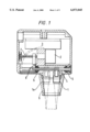
- FIG. 1 is a cross sectional view of a probe head for use in the present invention
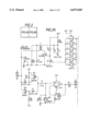
- FIG. 2 is a diagram of the circuit for the probe pulser and preamplifier of the present invention
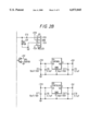
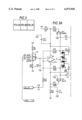
- FIG. 3 is a circuit diagram for the log amplifier system of the present invention.
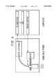
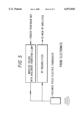
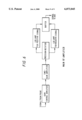
- FIG. 4 shows the system in a schematic form
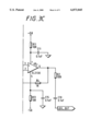
- FIG. 5 shows schematically the electronic systems of the probe
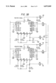
- FIG. 6 shows schematically the electronic systems of the main RF amplifier.
- FIG. 1 shows an apparatus for application to an area of skin, of a patient or hide.
- the apparatus comprises a transducer 1, which may be moved by means of a stepper motor 2 to scan an area of tissue on or under that particular area of skin.
- the motor 2 drives shaft 4, which is supported between an external shift bearing 5 and an internal shaft bearing 6, and the transducer 1 is movable between positions 1 and la as shown in FIG. 1.
- the transducer is driven along the shaft by means of flexible drive 7 although connection may also be made through link arm 8.
- the transducer 1, housed within cone 9, has preferably a piezoelectric polymer element capable of emitting a single cycle pulse at a frequency of between 10 and 50 MHz.
- the preferred centre frequency is in the region of 20 MHz and, as will be described below the probe transducer is activated at a high voltage, and the system is adapted to cause an ultra fast rise and fall time pulse. The sharp signals given thereby enable a better reception of the reflected signals.
- the control electronics of the system are housed in area 3 and are described in more detail below.
- the probe electronics contain a pulse generator for energising the ultrasound transducer and a preamplifier for the returning signal.
- the time gain compensator and motor control unit contains the main signal amplifier and the control and drive electronics for the probe motor. This may be connected to a compatible computer along with an analogue to digital converter board.
- the pulser which generates an ultra fast signal of rise and fall time (>30 kV/ ⁇ s) very short duration ( ⁇ 20 ns) high voltage pulse (>300V).
- the pulse is produced from a single low voltage (+12 volt) supply to the board.
- the pulse is created by the back emf of a small inductor acting as an impedance transformer with an avalanche transistor to limit the pulse duration and to produce an ultra fast fall time for the pulse.
- Pulse triggering is generated by a 3 ⁇ s 5 volt positive supplied to pin 1 of JPI. This causes the inputs to U2 of the 74HCT14 hex inverting Schmitt triggered buffer to go high for 3 ⁇ s.
- the turn on speed of Q1 is limited by R1 and the gate capacitance of Q1. This prevents a significant pulse from the in-rush current into T1, which saturates within 3 ⁇ s.
- the outputs of U2 go high turning Q2 on quickly which turns off Q1 in less than 10 ns. This causes a back emf pulse of in excess of 600 volts to be generated across T1.
- a preamplifier with input protection which consists of a standard current mode opamp with the input protected by a diode bridge.
- This amplifier has a voltage gain of 17 (12.3 dB).
- the received signal having been preamplified, is fed to a time gain compensation circuit to allow for attenuation through the various layers of tissue being investigated.
- An amplifier consists of five stages.
- the first stage is a variable gain amplifier with a -10 dB to +30 dB control. This acts as overall gain control for the system.
- the second stage is a variable gain amplifier and ramp generator with a 0 to +30 dB control range that is ramped at a controlled rate and acts as the time gain compensation.
- the third stage is a precision rectifier that splits the signal into the positive and negative parts of the signal, and for the fourth stage, a log compressor consisting of two 50 dB log amps. The output of these two log amps is recombined in the fifth stage and buffered to give a 50 ohm output for input to the analogue/digital converter.
- a motor control comprises a bipolar stepper motor drive using MOSFET transistors with phase sequencing provided by a specially programmed PAL.
- the step rate and step count is controlled by the host computer through an industrial standard 8254 counter/timer IC.
- the signal has an improved range and discrimination when transferred to an analogue digital converter and thence to the computing means and visual display means.
- Value can be added to the visual display by subjecting the returned signals either to a process of fractal analysis, wavelet analysis or a fast Fourier transform.
- Fractal analysis comprises representing the region of interest of the skin and underlying tissue as a three dimensional landscape, with lateral and axial dimensions on a horizontal plane and the intensity of the image (0-256) on a vertical axis.
- the area of landscape can then be mapped using flat disc shaped structuring elements with no height in a grey scale dimension and using techniques of mathematical morphology, the surface area of the image can be measured at different resolutions by removing features of less than a particular size. According to the method, this can be performed for resolutions between 1 pixel up to 20 pixels. At any given resolution, the rate of change of the surface area with respect to resolution is related to the estimated fractal dimension at that resolution.
- the set of estimated fractal dimensions up to resolutions of 20 pixels defines the fractal signature.
- Apparatus embodying the invention will find use in identifying and diagnosing tumours. injuries and any other abnormal condition up to depth of 3-5 cm below the skill surface being investigated. Such noninvasive investigation is obviously a benefit to the patient and the apparatus provides a means of carrying out such investigation quickly, and with the advantage of giving clear images of any problem which may be encountered within the tissue surveyed.
- One further use of the invention is in the testing of hides, sheepskins, and other materials used for commercial purposes such as clothing or footwear.
- the value of the hide will depend upon its surface perfection. This is not easy to see until the hair (or wool or the like) has been removed.
- the apparatus of the present invention can be used to scan a hide from an "inside” (deep) surface thereof and determine whether imperfections are likely to appear on the opposite "outside” surface once the hair has been removed.
Landscapes
- Engineering & Computer Science (AREA)
- Physics & Mathematics (AREA)
- Health & Medical Sciences (AREA)
- Radar, Positioning & Navigation (AREA)
- Remote Sensing (AREA)
- Life Sciences & Earth Sciences (AREA)
- Acoustics & Sound (AREA)
- Radiology & Medical Imaging (AREA)
- Molecular Biology (AREA)
- Biophysics (AREA)
- Nuclear Medicine, Radiotherapy & Molecular Imaging (AREA)
- Pathology (AREA)
- Computer Networks & Wireless Communication (AREA)
- Biomedical Technology (AREA)
- Heart & Thoracic Surgery (AREA)
- Medical Informatics (AREA)
- General Physics & Mathematics (AREA)
- Surgery (AREA)
- Animal Behavior & Ethology (AREA)
- General Health & Medical Sciences (AREA)
- Public Health (AREA)
- Veterinary Medicine (AREA)
- Ultra Sonic Daignosis Equipment (AREA)
- Image Processing (AREA)
- Image Analysis (AREA)
Priority Applications (1)
| Application Number | Priority Date | Filing Date | Title |
|---|---|---|---|
| US09/990,014 US20020032381A1 (en) | 1998-02-09 | 2001-11-21 | Method and apparatus for ultrasonic tissue investigation |
Applications Claiming Priority (3)
| Application Number | Priority Date | Filing Date | Title |
|---|---|---|---|
| GB9504751 | 1995-03-09 | ||
| GBGB9504751.0A GB9504751D0 (en) | 1995-03-09 | 1995-03-09 | Apparatus for ultrasonic tissue investigation |
| PCT/GB1996/000566 WO1996028096A1 (en) | 1995-03-09 | 1996-03-11 | Apparatus for ultrasonic tissue investigation |
Related Child Applications (1)
| Application Number | Title | Priority Date | Filing Date |
|---|---|---|---|
| US51026300A Continuation-In-Part | 1998-02-09 | 2000-02-22 |
Publications (1)
| Publication Number | Publication Date |
|---|---|
| US6073045A true US6073045A (en) | 2000-06-06 |
Family
ID=10770911
Family Applications (1)
| Application Number | Title | Priority Date | Filing Date |
|---|---|---|---|
| US08/894,791 Expired - Fee Related US6073045A (en) | 1995-03-09 | 1996-03-11 | Apparatus for ultrasonic tissue investigation |
Country Status (9)
| Country | Link |
|---|---|
| US (1) | US6073045A (de) |
| EP (1) | EP0957769B9 (de) |
| JP (1) | JPH11507846A (de) |
| AU (1) | AU721503B2 (de) |
| DE (1) | DE69635983T2 (de) |
| ES (1) | ES2264137T3 (de) |
| GB (1) | GB9504751D0 (de) |
| WO (1) | WO1996028096A1 (de) |
| ZA (1) | ZA961941B (de) |
Cited By (9)
| Publication number | Priority date | Publication date | Assignee | Title |
|---|---|---|---|---|
| US20040122319A1 (en) * | 2002-10-10 | 2004-06-24 | Mehi James I. | High frequency, high frame-rate ultrasound imaging system |
| US20060241495A1 (en) * | 2005-03-23 | 2006-10-26 | Eastman Kodak Company | Wound healing monitoring and treatment |
| US20070239001A1 (en) * | 2005-11-02 | 2007-10-11 | James Mehi | High frequency array ultrasound system |
| US20070263226A1 (en) * | 2006-05-15 | 2007-11-15 | Eastman Kodak Company | Tissue imaging system |
| US7761100B2 (en) | 2003-07-01 | 2010-07-20 | General Electric Co. | Ultra-low frequency electromagnetic tracking system |
| US7830069B2 (en) | 2004-04-20 | 2010-11-09 | Sunnybrook Health Sciences Centre | Arrayed ultrasonic transducer |
| US8316518B2 (en) | 2008-09-18 | 2012-11-27 | Visualsonics Inc. | Methods for manufacturing ultrasound transducers and other components |
| US9173047B2 (en) | 2008-09-18 | 2015-10-27 | Fujifilm Sonosite, Inc. | Methods for manufacturing ultrasound transducers and other components |
| US9184369B2 (en) | 2008-09-18 | 2015-11-10 | Fujifilm Sonosite, Inc. | Methods for manufacturing ultrasound transducers and other components |
Families Citing this family (3)
| Publication number | Priority date | Publication date | Assignee | Title |
|---|---|---|---|---|
| US6120445A (en) | 1998-10-02 | 2000-09-19 | Scimed Life Systems, Inc. | Method and apparatus for adaptive cross-sectional area computation of IVUS objects using their statistical signatures |
| US9451929B2 (en) | 2008-04-17 | 2016-09-27 | Boston Scientific Scimed, Inc. | Degassing intravascular ultrasound imaging systems with sealed catheters filled with an acoustically-favorable medium and methods of making and using |
| US8545412B2 (en) | 2009-05-29 | 2013-10-01 | Boston Scientific Scimed, Inc. | Systems and methods for making and using image-guided intravascular and endocardial therapy systems |
Citations (6)
| Publication number | Priority date | Publication date | Assignee | Title |
|---|---|---|---|---|
| EP0219128A2 (de) * | 1985-10-16 | 1987-04-22 | Hitachi Construction Machinery Co., Ltd. | Ultraschallprüfungsverfahren und Vorrichtung |
| US4858124A (en) * | 1984-08-15 | 1989-08-15 | Riverside Research Institute | Method for enhancement of ultrasonic image data |
| US5115814A (en) * | 1989-08-18 | 1992-05-26 | Intertherapy, Inc. | Intravascular ultrasonic imaging probe and methods of using same |
| US5394750A (en) * | 1984-06-04 | 1995-03-07 | Matzuk; Terrance | Tissue signature tracking transceiver |
| US5601082A (en) * | 1994-09-30 | 1997-02-11 | Intravascular Research Limited | Medical ultrasound imaging |
| US5721379A (en) * | 1993-11-13 | 1998-02-24 | The University Of Warwick | Electromagnetic acoustic transducers |
-
1995
- 1995-03-09 GB GBGB9504751.0A patent/GB9504751D0/en active Pending
-
1996
- 1996-03-11 EP EP96905953A patent/EP0957769B9/de not_active Expired - Lifetime
- 1996-03-11 ZA ZA961941A patent/ZA961941B/xx unknown
- 1996-03-11 JP JP8527376A patent/JPH11507846A/ja active Pending
- 1996-03-11 US US08/894,791 patent/US6073045A/en not_active Expired - Fee Related
- 1996-03-11 WO PCT/GB1996/000566 patent/WO1996028096A1/en not_active Ceased
- 1996-03-11 DE DE69635983T patent/DE69635983T2/de not_active Expired - Fee Related
- 1996-03-11 ES ES96905953T patent/ES2264137T3/es not_active Expired - Lifetime
- 1996-03-11 AU AU49509/96A patent/AU721503B2/en not_active Ceased
Patent Citations (6)
| Publication number | Priority date | Publication date | Assignee | Title |
|---|---|---|---|---|
| US5394750A (en) * | 1984-06-04 | 1995-03-07 | Matzuk; Terrance | Tissue signature tracking transceiver |
| US4858124A (en) * | 1984-08-15 | 1989-08-15 | Riverside Research Institute | Method for enhancement of ultrasonic image data |
| EP0219128A2 (de) * | 1985-10-16 | 1987-04-22 | Hitachi Construction Machinery Co., Ltd. | Ultraschallprüfungsverfahren und Vorrichtung |
| US5115814A (en) * | 1989-08-18 | 1992-05-26 | Intertherapy, Inc. | Intravascular ultrasonic imaging probe and methods of using same |
| US5721379A (en) * | 1993-11-13 | 1998-02-24 | The University Of Warwick | Electromagnetic acoustic transducers |
| US5601082A (en) * | 1994-09-30 | 1997-02-11 | Intravascular Research Limited | Medical ultrasound imaging |
Non-Patent Citations (4)
| Title |
|---|
| (French) Berson, et al., "Imagerie acoustique a haute resolution Applications en dermatologie," L'Onde Electrique, Mar./Apr. 1999, vol. 72, No. 2, pp. 31-35. |
| (French) Berson, et al., Imagerie acoustique a haute resolution Applications en dermatologie, L Onde Electrique, Mar./Apr. 1999, vol. 72, No. 2, pp. 31 35. * |
| Turnbull, et al., "Ultrasound Backscatter Microscope for Skin Imaging," 1993 Ultrasonics Symposium, published Oct. 31, 1993, pp. 985-988. |
| Turnbull, et al., Ultrasound Backscatter Microscope for Skin Imaging, 1993 Ultrasonics Symposium, published Oct. 31, 1993, pp. 985 988. * |
Cited By (20)
| Publication number | Priority date | Publication date | Assignee | Title |
|---|---|---|---|---|
| US8827907B2 (en) | 2002-10-10 | 2014-09-09 | Fujifilm Sonosite, Inc. | High frequency, high frame-rate ultrasound imaging system |
| US7255678B2 (en) | 2002-10-10 | 2007-08-14 | Visualsonics Inc. | High frequency, high frame-rate ultrasound imaging system |
| US20040122319A1 (en) * | 2002-10-10 | 2004-06-24 | Mehi James I. | High frequency, high frame-rate ultrasound imaging system |
| US7761100B2 (en) | 2003-07-01 | 2010-07-20 | General Electric Co. | Ultra-low frequency electromagnetic tracking system |
| US7830069B2 (en) | 2004-04-20 | 2010-11-09 | Sunnybrook Health Sciences Centre | Arrayed ultrasonic transducer |
| US20060241495A1 (en) * | 2005-03-23 | 2006-10-26 | Eastman Kodak Company | Wound healing monitoring and treatment |
| US20070239001A1 (en) * | 2005-11-02 | 2007-10-11 | James Mehi | High frequency array ultrasound system |
| USRE46185E1 (en) | 2005-11-02 | 2016-10-25 | Fujifilm Sonosite, Inc. | High frequency array ultrasound system |
| US7901358B2 (en) | 2005-11-02 | 2011-03-08 | Visualsonics Inc. | High frequency array ultrasound system |
| US7460248B2 (en) | 2006-05-15 | 2008-12-02 | Carestream Health, Inc. | Tissue imaging system |
| US20070263226A1 (en) * | 2006-05-15 | 2007-11-15 | Eastman Kodak Company | Tissue imaging system |
| US8316518B2 (en) | 2008-09-18 | 2012-11-27 | Visualsonics Inc. | Methods for manufacturing ultrasound transducers and other components |
| US9173047B2 (en) | 2008-09-18 | 2015-10-27 | Fujifilm Sonosite, Inc. | Methods for manufacturing ultrasound transducers and other components |
| US9184369B2 (en) | 2008-09-18 | 2015-11-10 | Fujifilm Sonosite, Inc. | Methods for manufacturing ultrasound transducers and other components |
| US9555443B2 (en) | 2008-09-18 | 2017-01-31 | Fujifilm Sonosite, Inc. | Methods for manufacturing ultrasound transducers and other components |
| US9935254B2 (en) | 2008-09-18 | 2018-04-03 | Fujifilm Sonosite, Inc. | Methods for manufacturing ultrasound transducers and other components |
| US10596597B2 (en) | 2008-09-18 | 2020-03-24 | Fujifilm Sonosite, Inc. | Methods for manufacturing ultrasound transducers and other components |
| US11094875B2 (en) | 2008-09-18 | 2021-08-17 | Fujifilm Sonosite, Inc. | Methods for manufacturing ultrasound transducers and other components |
| US11845108B2 (en) | 2008-09-18 | 2023-12-19 | Fujifilm Sonosite, Inc. | Methods for manufacturing ultrasound transducers and other components |
| US12029131B2 (en) | 2008-09-18 | 2024-07-02 | Fujifilm Sonosite, Inc. | Methods for patterning electrodes of ultrasound transducers and other components |
Also Published As
| Publication number | Publication date |
|---|---|
| EP0957769B1 (de) | 2006-03-29 |
| ES2264137T3 (es) | 2006-12-16 |
| ZA961941B (en) | 1996-09-20 |
| EP0957769B9 (de) | 2007-02-21 |
| EP0957769A1 (de) | 1999-11-24 |
| DE69635983T2 (de) | 2006-12-21 |
| WO1996028096A1 (en) | 1996-09-19 |
| JPH11507846A (ja) | 1999-07-13 |
| AU721503B2 (en) | 2000-07-06 |
| AU4950996A (en) | 1996-10-02 |
| GB9504751D0 (en) | 1995-04-26 |
| DE69635983D1 (de) | 2006-05-18 |
Similar Documents
| Publication | Publication Date | Title |
|---|---|---|
| US11672509B2 (en) | Shear wave elastrography method and apparatus for imaging an anisotropic medium | |
| US9687214B2 (en) | Ultrasonic measuring device, program, and method of controlling ultrasonic measuring device | |
| EP0957769B9 (de) | Vorrichtung zur untersuchung von gewebe mittels ultraschallwellen | |
| US11191523B2 (en) | Ultrasonic image construction method, ultrasonic image construction apparatus, ultrasonic image construction program, and skin evaluation method | |
| US11607202B2 (en) | Ultrasound diagnostic apparatus, method for controlling ultrasound diagnostic apparatus, and readable recording medium recording a program for controlling ultrasound diagnostic apparatus | |
| JPH11327A (ja) | 超音波診断装置 | |
| US20040120559A1 (en) | Methods and apparatus for contrast agent time intensity curve analyses | |
| CN114761827A (zh) | 量化介质的非线性剪切波弹性的超声波方法和用于实施该方法的设备 | |
| US7727152B2 (en) | Method and apparatus for scanning confocal acoustic diagnostic for bone quality | |
| US20180228377A1 (en) | Object information acquiring apparatus and display method | |
| US20260000381A1 (en) | Ultrasound diagnostic apparatus and method of controlling ultrasound diagnostic apparatus | |
| US20250352169A1 (en) | Ultrasonic diagnostic apparatus and method of controlling ultrasonic diagnostic apparatus | |
| EP4635422A1 (de) | Ultraschalldiagnosevorrichtung und verfahren zur steuerung der ultraschalldiagnosevorrichtung | |
| US20020032381A1 (en) | Method and apparatus for ultrasonic tissue investigation | |
| EP3578109A1 (de) | Ultraschalldiagnosevorrichtung, ultraschalldiagnosevorrichtungsteuerungsverfahren und ultraschalldiagnosevorrichtungsteuerungsprogramm | |
| US11083432B2 (en) | Yukov tissue characterization method and apparatus | |
| US11373307B2 (en) | Ultrasound diagnostic apparatus and method for controlling ultrasound diagnostic apparatus | |
| US20210150709A1 (en) | Ultrasonic image construction method, apparatus and signal-processing method | |
| EP4691373A1 (de) | Ultraschalldiagnosevorrichtung und steuerungsverfahren für die ultraschalldiagnosevorrichtung | |
| Edwards | The use of high frequency ultrasound to study dimensions and properties of skin | |
| EP4681653A1 (de) | Ultraschalldiagnosevorrichtung und verfahren zur steuerung der ultraschalldiagnosevorrichtung | |
| Ferreira et al. | Low-Cost Photoacoustic System for Biomedical Applications. | |
| Vacarescu et al. | Portable high-frequency device for cosmetic and clinical fingernail assessment | |
| CN116528773A (zh) | 信息处理装置、信息处理方法及程序 | |
| Thijssen et al. | Front-end for echographic image processing |
Legal Events
| Date | Code | Title | Description |
|---|---|---|---|
| AS | Assignment |
Owner name: UNITED MEDICAL AND DENTAL SCHOOL OF GUY'S & ST. TH Free format text: ASSIGNMENT OF ASSIGNORS INTEREST;ASSIGNORS:DYSON, MARY;YOUNG, STEPHEN ROBERT;LYNCH, JOHN ANDREW;AND OTHERS;REEL/FRAME:010230/0970;SIGNING DATES FROM 19971120 TO 19971207 Owner name: LONGPORT INCORPORATED, PENNSYLVANIA Free format text: ASSIGNMENT OF ASSIGNORS INTEREST;ASSIGNORS:SQUARE WAVE SYSTEMS LIMITED;UNITED MEDICAL AND DENTAL SCHOOL OF GUY'S AND ST. THOMAS'S HOSPITALS;REEL/FRAME:010230/0979;SIGNING DATES FROM 19980731 TO 19980821 Owner name: SQUARE WAVE SYSTEMS LIMITED, GREAT BRITAIN Free format text: ASSIGNMENT OF ASSIGNORS INTEREST;ASSIGNOR:LEWIS, HUGH;REEL/FRAME:010230/0973 Effective date: 19971125 |
|
| FEPP | Fee payment procedure |
Free format text: PETITION RELATED TO MAINTENANCE FEES FILED (ORIGINAL EVENT CODE: PMFP); ENTITY STATUS OF PATENT OWNER: SMALL ENTITY |
|
| FEPP | Fee payment procedure |
Free format text: PETITION RELATED TO MAINTENANCE FEES GRANTED (ORIGINAL EVENT CODE: PMFG); ENTITY STATUS OF PATENT OWNER: SMALL ENTITY Free format text: PAT HOLDER CLAIMS SMALL ENTITY STATUS, ENTITY STATUS SET TO SMALL (ORIGINAL EVENT CODE: LTOS); ENTITY STATUS OF PATENT OWNER: SMALL ENTITY |
|
| REIN | Reinstatement after maintenance fee payment confirmed | ||
| FPAY | Fee payment |
Year of fee payment: 4 |
|
| SULP | Surcharge for late payment | ||
| PRDP | Patent reinstated due to the acceptance of a late maintenance fee |
Effective date: 20040805 |
|
| FP | Lapsed due to failure to pay maintenance fee |
Effective date: 20040606 |
|
| REMI | Maintenance fee reminder mailed | ||
| FPAY | Fee payment |
Year of fee payment: 8 |
|
| SULP | Surcharge for late payment |
Year of fee payment: 7 |
|
| REMI | Maintenance fee reminder mailed | ||
| LAPS | Lapse for failure to pay maintenance fees | ||
| STCH | Information on status: patent discontinuation |
Free format text: PATENT EXPIRED DUE TO NONPAYMENT OF MAINTENANCE FEES UNDER 37 CFR 1.362 |
|
| FP | Lapsed due to failure to pay maintenance fee |
Effective date: 20120606 |