US6060809A - Staggered pole switched reluctance motor - Google Patents
Staggered pole switched reluctance motor Download PDFInfo
- Publication number
- US6060809A US6060809A US09/170,809 US17080998A US6060809A US 6060809 A US6060809 A US 6060809A US 17080998 A US17080998 A US 17080998A US 6060809 A US6060809 A US 6060809A
- Authority
- US
- United States
- Prior art keywords
- rotor
- stator
- pole
- poles
- phase
- Prior art date
- Legal status (The legal status is an assumption and is not a legal conclusion. Google has not performed a legal analysis and makes no representation as to the accuracy of the status listed.)
- Expired - Fee Related
Links
Images


Classifications
-
- H—ELECTRICITY
- H02—GENERATION; CONVERSION OR DISTRIBUTION OF ELECTRIC POWER
- H02K—DYNAMO-ELECTRIC MACHINES
- H02K19/00—Synchronous motors or generators
- H02K19/02—Synchronous motors
- H02K19/10—Synchronous motors for multi-phase current
- H02K19/103—Motors having windings on the stator and a variable reluctance soft-iron rotor without windings
-
- H—ELECTRICITY
- H02—GENERATION; CONVERSION OR DISTRIBUTION OF ELECTRIC POWER
- H02K—DYNAMO-ELECTRIC MACHINES
- H02K29/00—Motors or generators having non-mechanical commutating devices, e.g. discharge tubes or semiconductor devices
- H02K29/03—Motors or generators having non-mechanical commutating devices, e.g. discharge tubes or semiconductor devices with a magnetic circuit specially adapted for avoiding torque ripples or self-starting problems
-
- H—ELECTRICITY
- H02—GENERATION; CONVERSION OR DISTRIBUTION OF ELECTRIC POWER
- H02K—DYNAMO-ELECTRIC MACHINES
- H02K1/00—Details of the magnetic circuit
- H02K1/06—Details of the magnetic circuit characterised by the shape, form or construction
- H02K1/22—Rotating parts of the magnetic circuit
- H02K1/24—Rotor cores with salient poles ; Variable reluctance rotors
-
- H—ELECTRICITY
- H02—GENERATION; CONVERSION OR DISTRIBUTION OF ELECTRIC POWER
- H02K—DYNAMO-ELECTRIC MACHINES
- H02K19/00—Synchronous motors or generators
- H02K19/16—Synchronous generators
- H02K19/22—Synchronous generators having windings each turn of which co-operates alternately with poles of opposite polarity, e.g. heteropolar generators
- H02K19/24—Synchronous generators having windings each turn of which co-operates alternately with poles of opposite polarity, e.g. heteropolar generators with variable-reluctance soft-iron rotors without winding
-
- H—ELECTRICITY
- H02—GENERATION; CONVERSION OR DISTRIBUTION OF ELECTRIC POWER
- H02K—DYNAMO-ELECTRIC MACHINES
- H02K41/00—Propulsion systems in which a rigid body is moved along a path due to dynamo-electric interaction between the body and a magnetic field travelling along the path
- H02K41/02—Linear motors; Sectional motors
- H02K41/03—Synchronous motors; Motors moving step by step; Reluctance motors
Definitions
- This invention relates to electronically commuted switched reluctance machines and more particularly to continuous rotation motors operated by sources of polyphase electric energy.
- Switched reluctance motors are well known in the art. These motors have a stationary member, typically called a stator, and a movable member, typically called a rotor The rotor and stator are oriented such that they move relative to each other.
- a typical stator includes a yoke supporting a plurality of magnetically permeable poles circumferentially spaced and having gaps therebetween.
- a typical rotor includes a magnetically permeable body comprised of laminations of magnetically permeable steel forming two or more poles circumferentially spaced and having gaps therebetween.
- the rotor is disposed relative to the stator such that their respective poles pass closely adjacent, when the rotor is moved relative to the stator, i.e., the poles of the rotor move in spaced relation to the poles of the stator.
- the motor has phase windings on the poles of the stator but not on the poles of the rotor.
- Switched reluctance motors rely on polyphase electronic commutation to excite these phase windings in proper sequence to cause movement of the rotor relative to the stator. Specifically, excitation of the phase windings produces on the stator a pole pair having a north pole and a south pole.
- phase windings create a magnetic flux path that passes through the polarized pole pairs, the rotor and the yoke of the stator, i.e., a magnetic circuit.
- the rotor moves to bring a pair of rotor poles into a minimum reluctance position relative to the polarized pair of stator poles. This minimum reluctance position corresponds to the maximum inductance of the energized phase winding.
- a feature common to two phase SR motors is that the rotor is typically configured to optimize rotation in one direction.
- SR motors switched reluctance motors
- SR motors are efficient in converting electrical energy into mechanical work, they are reliable because of their mechanical simplicity and they are capable of significant rotational speeds, i.e., 100,000 RPM. Additionally, SR motors are inexpensive to produce, they are rugged and robust and do not require brushes or slip rings.
- Some polyphase source and stator/rotor combinations include, without limitation, two phase 8/4 motor; three phase 6/4 motor; four phase 8/6 motor and a five phase 10/8 motor.
- One reason for increasing the number of stator and rotor poles and for having higher numbers of phases is to increase the number of electronic phase commutations per revolution thereby minimizing torque dips or torque ripple between the phases.
- Torque in an SR motor is related to changing inductance (dL) of energized phase windings as a function of rotor position.
- Inductance in an SR motor decreases or increases as the poles of the rotor move into or out-of alignment with the poles associated with the energized stator windings, i.e., as the rotor-stator system moves into or out-of a minimum reluctance position.
- torque is produced when there is a change in inductance as a function of angular position, i.e., dL/d ⁇ ; positive torque being produced when the inductance of an energized phase increases and negative torque being produced when the inductance of an energized phase decreases.
- a problem with prior art two phase SR motors is that at certain angular positions of the rotor relative to the stator, the torque experienced by the rotor is zero or a very small percentage of maximum torque. This position of little or no torque results from the poles of the rotor and the stator being positioned relative to each other such that insufficient flux from an energized stator pole pair passes through a pair of rotor poles to cause relative motion therebetween. Attempts at overcoming this problem included modifying the geometries of the rotor poles such that portions of the rotor pole are in sufficient flux communication with an energized stator pole to impart torque to the rotor.
- One such geometry includes a stepped gap rotor wherein a first portion of the face of a rotor pole coming into flux communication with the energizing stator pole forms a gap with the face of the stator pole having a first gap space. The second portion of the face of the rotor pole coming into flux communication with the face of the stator pole forms a second gap that is narrower than the first gap space; the transition between the first gap space and the second gap space being a step.
- Another geometry includes a snail-cam design wherein the face of the rotor pole tapers such that the gap between the rotor and the stator becomes progressively smaller as the rotor rotates into minimum reluctance position with respect o the stator.
- the faces of the rotor poles are widened such that the first portion of the rotor pole extends towards an adjacent deenergized stator pole when the second portion of the rotor pole is in a minimum reluctance position with an energized stator pole.
- An attempt at overcoming torque ripple in SR motors includes increasing the number of commutation phases to 3 or more. It is well known that torque ripple generally decreases with an increasing number of motor phases. Specifically, 3 phase motors generally have less torque ripple than 2 phase motors, 4 phase motors have less torque ripple than 3 phase motors and so on.
- the decrease in torque ripple with increasing phases results from the dL/d ⁇ from one phase being non-zero before the dL/d ⁇ from an immediately preceding phase becoming zero.
- increasing the number of phases to 3 or more produces closely adjoining or overlapping dL/d ⁇ such that the rotor experiences torque from the energization of one phase before the termination of torque from the energization of another phase.
- a switched reluctance motor having an inner stator with a plurality of evenly spaced, outwardly extending poles disposed thereon.
- An annular rotor surrounds the stator and is mounted for rotation about a longitudinal axis relative to the poles of the stator.
- the rotor has a plurality of inward extending poles disposed thereon.
- At least one of the rotor poles has a rotor pole face of a first size and another of the rotor poles has a rotor pole face of a second size greater than the first size.
- Windings for two phases are wound about poles of the stator that are separated by a winding and an associated stator pole of the opposite phase.
- a phase winding is disposed around a pole of the stator and electrically connected to one phase of an electrical power source for energization thereby.
- an SR motor having a stator with a plurality of magnetically permeable stator poles evenly spaced circumferentially about a central axis, each of the stator poles extending outward from the axis and traversing a first stator angle.
- An annular rotor is mounted for rotation relative to the stator about the axis. The rotor has an even number of magnetically permeable poles unevenly spaced about the axis.
- the rotor poles extend toward the axis and include a pole having a narrow face that traverses a first rotor angle, wherein the first rotor angle is approximately equal to the first stator angle, and a pole having a wide face that traverses a second rotor angle that is approximately twice the first rotor angle.
- a switched reluctance motor driven by a two phase source having a stator having a plurality of evenly spaced like poles defining a uniform gap between adjacent stator poles. Windings for each of the two phases of the motor are wound about stator poles that are circumferentially separated by a winding and an associated stator pole of a different phase.
- a rotor is mounted for rotation around the stator and has a wide rotor pole and a narrow rotor pole.
- the rotor is dimensioned such that a first sector of the wide rotor pole is in alignment with a first stator pole when the narrow rotor pole is aligned with a second stator pole and a second sector of the wide rotor pole is in alignment with the first stator pole when the narrow rotor pole is aligned with the gap adjacent the second stator pole.
- a switched reluctance motor driven by a two phase source having a stator with a plurality of like poles, each having a stator pole face.
- the stator poles are uniformly spaced to define a uniform gap between adjacent stator poles.
- Windings are provided for each of the phases of the motor and are wound about stator poles that are circumferentially separated by at least one winding and an associated stator pole of a different phase.
- a rotor is mounted for rotation about the periphery of the stator.
- the rotor has a wide rotor pole face.
- the rotor is dimensioned such that the narrow pole face is approximately equal to a stator pole face and the wide rotor pole face spans at least the pole face of a first stator pole and the gap adjacent the first stator when the narrow pole face is aligned with the pole face of a second stator pole.
- a switched reluctance motor having an inner stator with a plurality of evenly spaced like stator poles, the number of stator poles being a whole multiple of four.
- a rotor having a plurality of rotor poles is mounted for rotation around the stator.
- the number of rotor poles is one-half the number of stator poles, and half of the rotor poles are wide rotor poles and half of the rotor poles being narrow rotor poles.
- a narrow rotor pole is disposed on each side of a wide rotor pole.
- the rotor dimensioned such that the narrow rotor poles have pole has a pole face approximately equal to the pole face of a stator pole and the gap between adjacent stator poles. Windings for two phases are wound about stator poles that are circumferentially separated by at least one winding and an associated stator pole of a different phase. A pair of adjacent stator poles is connected to have the same polarity.
- a switched reluctance motor driven by a two phase source having an inner stator with a plurality of evenly spaced like poles defining a uniform gap between adjacent stator poles. Windings for each of the two phases of the motor are wound about stator poles that are circumferentially separeted by a winding and an associated stator pole of a different phase.
- a rotor is mounted for rotation around the stator having a wide rotor pole and a narrow rotor pole.
- the rotor is dimensioned such that the energization of a phase causes a wide rotor pole to interact with a first stator pole to induce a first torque on the rotor and to produce a first predetermined angular rotation of the rotor, and thereafter a first narrow pole interacts with a second stator pole to induce a second torque on the rotor and to produce a second predetermined angular rotation on the rotor.
- a switched reluctance motor driven by a two phase source having an inner stator with a plurality of evenly distributed, like poles thereon, each of the poles having a stator pole face. Windings for each of the phases of the motor are wound about stator poles that are circumferentially separated by at least one winding and an associated stator pole of a different phase.
- An outer rotor mounted for rotation around the stator. The rotor has a wide rotor pole having a wide rotor pole face and a narrow rotor pole has a narrow rotor pole face.
- the rotor is dimensioned such that energization of one of the phases causes a predetermined angular rotation of the rotor wherein a first portion of the angular rotation is created by a wide rotor pole being drawn into a minimum reluctance position relative to one of the energized stator poles and the other portion of the angular rotation is created by a narrow rotor pole being drawn into a minimum reluctance position with another of the energized stator poles.
- a switched reluctance motor driven by a two phase source having a stator with a plurality of like poles evenly distributed thereon to define a uniform gap between each pole, each of the poles having a stator pole face. Windings for each of the phases of the motor are wound about stator poles that are circumferentially separated by at least one winding and an associated stator pole of a different phase.
- An annular rotor is mounted for rotation around the stator.
- the rotor has a wide rotor pole having a wide rotor pole face and a narrow rotor pole having a narrow rotor pole face.
- the rotor is dimensioned such that a uniform gap is defined between the rotor pole faces and the stator pole faces and energization of one of the phases, wherein the wide rotor pole magnetically interacts with a first stator pole and the narrow rotor pole magnetically interacts with a second stator pole to cause the rotor to rotate a predetermined angular amount wherein the area of overlap of the wide rotor pole face and the narrow rotor pole face relative to the first and second stator poles faces increase at a generally uniform rate as the rotor moves the predetermined angular amount.
- a switched reluctance motor driven by a two phase source.
- the motor has an inner stator having a plurality of like poles evenly distributed thereon, each of the poles having a stator pole face. Windings for each of the phases of the motor are wound about stator poles that are circumferentially separated by at least one winding and an associated stator pole of a different phase.
- a rotor surrounds the stator and is mounted for rotation relative to the stator.
- the rotor has a wide rotor pole having a wide rotor pole face and a narrow rotor pole having a narrow rotor pole face.
- the rotor poles are dimensioned relative to the stator poles such that the motor has an inductance-to-angular rotation profile, wherein the inductance of a phase increases over a first angle of rotation and decreases over a second angle of rotation and the first angle of rotation is approximately twice the second angle of rotation.
- a switched reluctance motor driven by a two phase source comprising: a stator having a yoke and a (2 X) number of evenly spaced, like poles distributed on the yoke defining a gap between each stator pole. Windings for each of the two phases of the motor are wound about stator poles that are circumferentially separated by a winding and an associated stator pole of a different phase. A rotor is mounted for rotation relative to the stator.
- the rotor having (X) number of rotor poles and the rotor is dimensioned such that, during each phase energization, the motor has a first state wherein (1/2 X) number of rotor poles are magnetically coupled to a like number of stator poles and a second state wherein (X) number of rotor poles are magnetically coupled to a like number of stator poles.
- a switched reluctance motor driven by a two phase source comprising a stator having a yoke and an even number of evenly-spaced, like stator poles distributed on the yoke defining a gap between each stator pole. Windings for each of the two phases of the motor are wound about stator poles that are circumferentially separated by a winding and an associated stator pole of a different phase. A rotor is mounted for rotation relative to the stator.
- the rotor has an even number of rotor poles, and the rotor poles are dimensioned such that when the phases are alternately energized, the rotor poles operatively interact with the stator poles such that the motor oscillates between a first state wherein half of the rotor poles are magnetically coupled to a like number of the stator poles, and a second state wherein all of the rotor poles are magnetically coupled to a like number of stator poles.
- An advantage of the present invention is the improved torque experienced by the rotor at all positions of the rotor relative to the stator.
- Another advantage of the present invention is the improved torque characteristics of a 2 phase SR motor making a two phase SR motor applicable to applications heretofore requiring an SR motor having 3 or more phases.
- Still another advantage of the present invention is reduced torque ripple.
- Yet another advantage of the present invention is the improved electrical power output over prior art generators.
- a still further advantage of the present invention is a two phase, SR motor having an inner stator and an outer rotor.
- a still further advantage of the present invention is a two phase SR motor that is quieter than two-phase SR motors known heretofore.
- a still further advantage of the present invention is a two phase SR motor that, during each phase energization, has a first state wherein a predetermined number of rotor and stator poles are magnetically coupled, and a second state wherein twice said predetermined number of rotor and stator poles are magnetically coupled.
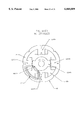
- FIG. 1 is a sectional view of an 8/4 switched reluctance motor in accordance with the present invention.
- FIG. 2 is the motor of FIG. 1 with associated control and operational circuitry connected thereto and showing the rotor advanced by 15 mechanical degrees relative to the motor of FIG. 1.
- FIGS. 3-4 are isolated views of the rotor and stator of FIG. 1 showing the rotor advanced by 30 and 45 mechanical degrees respectively relative to the motor of FIG. 1.
- FIGS. 5(a)-5(f) are isolated views of the rotor and stator of FIG. 1 showing mechanical progression of the rotor in a CCW direction relative to the stator in response to the generation of north and south pole pairs by the excitation of the phase A and phase B windings, removed for the purpose of illustration.
- FIGS. 6(a)-6(f) are flux plots corresponding to the phase energization and rotor and stator positions of FIGS. 5(a)-5(f).
- FIG. 7(a) is an exemplary ideal inductance profile of the phase A and phase B stator windings of FIG. 1 with respect to the CCW mechanical progression of the rotor relative to the stator.
- FIG. 7(b) is an ideal energization profile of the phase A and phase B windings of FIG. 1 for the inductance profile of FIG. 7(a).
- FIG. 8 is an inductance profile of the phase A and phase B stator windings of FIG. 1 with respect to the CCW progression of the rotor relative to the stator.
- FIG. 9(a) is the static torque curves for the Phase A and Phase B windings at 1.5A, 2.0A, 2.5A and 3.0A phase energization current for the inductance profile of FIG. 8.
- FIG. 9(b) is an energization profile of the phase A and phase B stator windings for the static torque curves of FIG. 9(a).
- FIG. 9(c) is the torque curves resulting from the combination of the Phase A and Phase B torque curves of FIG. 9(a).
- FIG. 10 is a sectional view of an 16/8 switched reluctance motor in accordance with the present invention.
- FIG. 11(a) is a sectional views of an 4/2 switched reluctance motor in accordance with the present invention with associated control and operational circuitry connected thereto.
- FIGS. 11(b)-11(c) are isolated views of the 4/2 switched reluctance motor of FIG. 11(a) showing the rotor advanced by 45 and 90 degrees respectively relative to the motor of FIG. 11(a) in response to the generation of north and south pole pairs by the excitation of the phase A and phase B windings.
- FIG. 12 is a linear actuator in accordance with the present invention.
- FIGS. 13(a)-13(e) are isolated views of a rotor and stator in accordance with a stator implementation of the present invention showing mechanical progression of the rotor in a CW direction relative to the stator in response to the generation of north and south pole pairs by the excitation of phase A and phase B windings, removed for illustration purposes.
- FIG. 14 is a sectional view of a switched reluctance motor-generator in accordance with the present invention with associated control and operational circuitry connected thereto.
- FIG. 15 is a sectional view of an 8/4, 2-phase switched reluctance motor having an inner stator and an outer rotor illustrating an alternate embodiment of the present invention.
- FIG. 16 is a sectional view of the motor shown in FIG. 15, showing the rotor advanced clockwise 15 mechanical degrees relative to the stator.
- FIGS. 17 and 18 are views of the motor shown in FIG. 15, showing the rotor advanced clockwise by 22.5 and 45 mechanical degrees, respectively, relative to the stator.
- FIG. 19 is an ideal energization profile of phases A and B of the motor shown in FIG. 15.
- FIGS. 20-23 are sectional views of the motor shown in FIG. 15, showing flux plots corresponding to the rotor and stator positions shown in FIGS. 15-18.
- FIG. 1 a sectional view of a two phase 8/4 switched reluctance motor 10 in accordance with the present invention is illustrated.
- the motor has a stator 12 having a magnetically permeable member 14 disposed around a central bore 16 and defining a plurality of poles 18(a)-18(h).
- the stator has an even number of poles, and while eight poles are shown in FIG. 1, the stator can have a different even number of poles.
- a rotor 20 is disposed in the central bore for rotation therein.
- the rotor has 4 poles 22(a)-22(d), however, the rotor can have a different even number of poles.
- Phase windings 24, 26 are disposed around the phase A and phase B stator poles respectively for generating magnetic fields that extend from the stator poles into the central bore. Phase windings 24 and 26 are alternately disposed on every other stator pole and are wound such that for every pole of one polarity there is a corresponding pole of an opposite polarity.
- phase A poles 18(a) and 18(c) are north poles and phase A poles 18(e) and 18(g) are south poles.
- phase B poles 18(f) and 18(h) are north poles and phase B poles 18(b) and 18(d) are south poles. It is to be appreciated, that the pole polarity is for illustration purposes only and is not to be construed as limiting the invention.
- phase windings A and B are series connected to sources of switched current 30 and 32 respectively such that current flows through the phase windings only in one direction. It is to be appreciated, however, that the phase windings could be parallel connected or combination series-parallel connected to their respective sources of switched current.
- a position sensor 36 such as a hall effect sensor, a resolver or an encoder, is connected between the rotor and the stator for determining the position of the rotor relative to the stator. Alternatively, self inductance of the phase windings are used to determine the position of the stator relative to the rotor.
- the position sensor has an output connected to a controller 38 for reporting the angular position of the rotor relative to the stator.
- the controller 38 is connected to the phase A and phase B phase drivers for controlling the firing of the respective phases in accordance with the position of the rotor relative to the stator.
- An optional speed control 39 connected to controller 38 provides for adjustment of the rotational speed of the rotor.
- motor 10 is a unidirectional motor in which the rotor rotates counterclockwise (CCW) with respect to the stator. It is to be appreciated, however, that motor could be designed for clockwise (CW) rotation and that the direction of rotation is not to be construed as limiting the invention.
- the poles of the rotor are disposed unevenly about the circumference thereof.
- the angle between rotor poles 22(a)-22(b) and 22(c)-22(d) is a first angle 41
- the angle between rotor poles 22(b)-22(c) and 22(a)-22(d) is a second angle 42, greater than the first angle.
- the faces of the wide rotor poles span a third angle 43 and the faces of the narrow rotor poles span a forth angle 44 less; the third angle being greater than the forth angle.
- the face of the wide rotor poles are twice as wide as the face of the narrow rotor poles.
- the face of the stator poles are approximately the same width as the face of the narrow rotor poles and the distance between adjacent stator poles is approximately the width of a stator pole.
- FIGS. 5(a)-5(f) With reference to FIGS. 5(a)-5(f), the CCW progression of the rotor with respect to the stator, in response to the generation of north-south pole pairs by the excitation of associated phase windings, is illustrated.
- the phase windings, the phase A and phase B drivers, the controller/power supply, the speed control and the position sensor of FIGS. 1 and 2 have been omitted to facilitate uncluttered views of the rotor and stator.
- the poles associated with an excited phase are marked with either an ⁇ N ⁇ or an ⁇ S ⁇ to signify a north or south pole respectively.
- the controller 38 causes the phase B current source 32 to energize the phase B windings in the absence of excitation of the phase A windings.
- This excitation produces a CCW torque on the rotor causing the rotor to align the wide rotor poles with excited phase B stator poles 18(d) and 18(h), i.e., the rotor poles move into minimum reluctance position with respect to the phase B poles--the minimum reluctance position corresponding to the maximum inductance of the energized phase windings producing said alignment.
- the wide rotor poles and adjacent energized phase B stator poles are in a minimum reluctance position with respect to each other as a result of a constant gap being formed therebetween.
- the inductance of the phase B windings increases due to the narrow rotor poles 22(b) and 22(d) moving to a minimum reluctance position with stator poles 18(b) and 18(f). Accordingly, the rotor experiences a torque due to the interaction of the narrow rotor poles with the energized phase B windings while experiencing little or no torque from the interaction of the wide rotor poles with the energized phase B windings.
- the wide and narrow rotor poles are in minimum reluctance position with energized phase B stator poles 18(d)-18(h) and 18(b)-18(f) respectively. Accordingly, at this position no torque is imparted to the rotor from the energization of the phase B windings.
- Energizing the phase A windings at 45 degrees CCW rotor position causes flux to flow from phase A poles 18(a) and 18(e) through the wide rotor poles. In response to flux flowing therethrough, the rotor experiences a CCW torque causing the rotor to align the wide poles with the poles of the excited phase A windings.
- phase B windings experience a decrease in inductance due to the increasing reluctance between the stator poles of the phase B windings and the rotor poles.
- the phase B windings are deenergized. In this manner, the torque experienced by the rotor shifts from the phase B windings to the phase A windings.
- the wide rotor poles and energized phase A stator poles 18(a) and 18(e) are in a minimum reluctance position such that no torque is imparted to the rotor from the interaction thereof.
- the inductance of the energized phase A windings is increasing due to the narrow rotor poles coming into flux communication with energized phase A stator poles 18(c) and 18(g).
- torque imparted to the rotor from the energized phase windings shifts from the wide rotor poles to the narrow rotor poles.
- the wide and narrow rotor poles are in minimum reluctance alignment with stator poles 18(a)-18(e) and 18(c)-18(g) respectively. Accordingly, the rotor experiences no torque from the interaction of the wide rotor poles with the phase A windings.
- Energizing the phase B windings causes flux to flow from phase B poles 18(b) and 18(f) through the wide rotor poles.
- the rotor experiences a CCW torque causing the rotor to align the wide poles with the excited phase B windings.
- the phase A windings are deenergized.
- FIGS. 6(a)-6(f) magnetic flux plots corresponding to the rotor positions and phase energizations of FIGS. 5(a)-5(f) are illustrated.
- FIGS. 6(a)-6(b) between 0 and 22.5 degrees CCW rotor position a greater amount of flux flows through the wide rotor poles than through the narrow rotor poles.
- FIGS. 6(b)-6(c) between 22.5 and 30 degrees CCW rotor position the amount of flux passing through the narrow rotor poles increases as the narrow rotor poles move into minimum reluctance position with stator poles 18(b) and 18(f).
- the rotor is advanced through 90 mechanical degrees by the selective energization and deenergization of the phase A and phase B windings in relation to the position of the rotor relative to the stator. It is to be appreciated, however, that the above description is extendable to movement of the rotor beyond 90 mechanical degrees. Moreover, it is to be appreciated that the increasing or decreasing inductance of a phase winding corresponds to the respective decreasing or increasing reluctance in the magnetic flux path associated with said phase winding.
- the present invention produces in the phase A and phase B windings a change in inductance with angular position (dL/d ⁇ ) having a slope that increases at a first rate and decreases at a second rate.
- a change in inductance with angular position (dL/d ⁇ ) having a slope that increases at a first rate and decreases at a second rate.
- FIGS. 7(a)-7(b) an exemplary ideal inductance profile for the change in inductance of the phase B windings 50 and the phase A windings 52 as a function of the CCW position of the rotor and in relation to ideal energization of the phase A and phase B windings is illustrated.
- FIGS. 7(a)-7(b) are for illustration purposes and are not to be construed as limiting the invention.
- phase B windings are energized in the absence of the energization of the phase A windings.
- the rotor experiences a CCW torque that urges the rotor and stator combination towards a minimum reluctance, maximum inductance, position.
- Concurrent with the increasing inductance of the phase B windings the inductance of phase A windings is decreasing.
- the inductance of each phase of the novel pole configuration decreases more rapidly than it increases. This allows for advantageous overlap of the increasing inductance of the phase A and phase B windings.
- phase A windings transitions from decreasing to increasing and the phase A windings are energized.
- both phase windings are energized and the inductance of both phase windings are increasing. Accordingly, the rotor experiences torque from both the phase A and phase B windings.
- phase B inductance transitions from increasing to decreasing and the phase B windings are deenergized.
- the rotor experiences a positive CCW torque from the energization of the phase A windings in cooperation with the increase in inductance thereof while avoiding a negative CW torque from the energization of the phase B windings in cooperation with the decrease in inductance thereof.
- the inductance of the phase B windings transitions from decreasing to increasing and the phase B windings are energized.
- the increasing inductance of the phase A and phase B windings in cooperation with the energization thereof imparts a torque to the rotor.
- the inductance of the phase A windings transitions from increasing to decreasing and the phase A windings are deenergized such that torque is imparted onto the rotor exclusively from the increasing inductance of phase B in cooperation with the energization thereof.
- the inductance of phase A transitions from decreasing to increasing and the phase A windings are energized. Accordingly, between 127 and 135 degrees rotor position the phase A and phase B windings impart a torque to the rotor.
- the inductance of the phase B windings transitions from increasing to decreasing and the phase B windings are deenergized such that the torque imparted onto the rotor is exclusively from the increasing inductance of phase A in cooperation with the energization thereof.
- the present invention produces in the phase A and phase B windings a change in inductance as a function of rotor position wherein the inductance of a phase winding increases at a different rate than the inductance thereof decreases. Specifically, the increasing inductance of each phase extends over a greater angular position than the decreasing inductance thereof.
- the phase B inductance decreases between 45 and 82 degrees rotor position, i.e., over 37 mechanical degrees, and increases between 82 and 135 degrees rotor position, i.e., over 53 mechanical degrees.
- phase A inductance increases between 37 and 90 degrees rotation, i.e., over 53 mechanical degrees, and decreases between 90 and 127 degrees rotation, i.e., over 37 mechanical degrees.
- the differing slopes of increasing and decreasing inductance of the phase A and phase B windings allows for the advantageous overlap thereof as illustrated in FIG. 7(a) and described above. This overlap of increasing inductance in cooperation with the selective energization of the phase A and phase B windings provides for torque to be imparted onto the rotor at all positions of the rotor relative to the stator.
- FIG. 8 an inductance profile of the embodiment illustrated in FIGS. 5(a)-5(f) is illustrated.
- the inductance profile of FIG. 8 illustrates that the transition between increasing and decreasing inductance of the phase A and phase B windings occurs gradually as the rotor poles move into and out-of alignment with the stator poles. Because positive, CCW, torque on the rotor is a function of increasing inductance of an energized phase winding, it is desirable to coordinate the energization of the phase windings with the rotor position to ensure the phase windings are experiencing an increasing inductance when energized.
- phase B windings are energized and the phase A windings are deenergized.
- phase A windings are energized and the phase B windings are deenergized in a manner that results in minimal torque ripple being experienced by the rotor as the torque imparted to the rotor transitions from the phase B windings to the phase A windings.
- phase A windings are deenergized and the phase B windings are energized in a manner that results in minimal torque ripple being experienced by the rotor.
- the inductance of the respective phases instantaneous energization and deenergization thereof. Accordingly, in practice, the energization and deenergization of the respective phases is timed to occur such that the torque experienced by the rotor is optimized.
- the phase B windings are deenergized such that the energy stored therein is dissipated in advance of the phase B windings experiencing a decreasing inductance thereby imparting a negative CW torque onto the rotor.
- the phase A windings are energized thereby imparting a positive CCW torque onto the rotor.
- the energization for the respective windings can be timed to optimize the torque experienced by the rotor.
- the rotor experiences a relatively constant torque with rotor position.
- the rotor experiences some torque dip as the torque imparted thereon transitions between the respective phase windings.
- the width of the rotor poles affect the inductance profile of FIG. 8.
- the face of the narrow poles, 22(b) and 22(d) are approximately the same width as the face of the stator poles while the face of the wide rotor poles, 22(a) and 22(c), are illustrated as being approximately the same width as the combined width of the face of a stator pole and an adjacent space, e.g., stator pole 22(a) and space 52.
- This arrangement advantageously provides for the aforementioned overlap of increasing inductance of the phase windings. It is believed, however, that the overlap of the phase A and phase B inductance profiles are adjustable by modifying the width of rotor poles.
- torque curves for the embodiment shown in FIGS. 5(a)-5(f), at different phase winding energization currents, i.e., 1.5A, 2.0A, 2.5A and 3.0A, are illustrated in relation to the phase energization profile thereof.
- These torque curves illustrate the torque imparted to the rotor from the energization of the respective phase windings and the advantageous overlap thereof. It is to be appreciated that the torque experienced by the rotor is the sum of the torque produced by the energization of the respective phase A and phase B windings.
- phase energization currents e.g., 2.5A and 3.0A
- lower torque ripple at lower phase energization currents e.g., 2.0A and 1.5A.
- the energization of the phase A and phase B windings are selected to coincide with the position of the rotor relative to the stator.
- FIG. 9(b) the energization of the phase A and phase B windings are illustrated as overlapping to take advantage of the increasing inductance of the respective phase A and phase B windings as a function of rotor position. In this manner, the rotor experiences minimal torque ripple with rotor rotation.
- the torque curves and energization profiles of FIGS. 9(a)-9(b) are for illustration purposes and should not to be construed as limiting the invention.
- the overlap of the energization of the phase A and phase B windings could be more or less, or the energization of the phase A and phase B windings could have no overlap depending on, without limitation, the inductance of the windings, the capacity of the commutation electronics to quickly deenergize the phase windings, the rotational speed of the rotor and/or the desired operating characteristics of the motor.
- the 8/4 embodiment set forth above is extendable to embodiments of two phase SR motors having different numbers of rotor and stator poles.
- One such embodiment includes the 16/8 SR motor illustrated in FIG. 10 wherein the motor includes phase A and phase B windings disposed around alternating stator poles and connected to phase A and phase B phase drivers, a controller/power supply, and an optional position sensor.
- the polarity of the phase A and phase B poles is not to be construed as limiting the invention or as an indication that the phase windings are energized.
- the motor has a stator 60 comprised of a plurality of inwardly extending poles 62(a)-62(d) defining a central bore 64.
- a rotor 66 comprised of two outwardly extending poles 68(a)-68(b), is disposed in the central bore for rotation therein.
- Phase windings 70 and 72 are disposed around opposing stator poles 62(b)-62(d) and opposing stator poles 62(a)-62(c) respectively for generating magnetic fields that extend from the stator poles into the central bore.
- phase windings 70 and 72 are connected to the phase A phase driver 30 and the phase B phase driver 32 respectively such that current flows through the phase windings in one direction.
- a position sensor 36 is connected between the rotor and stator for determining the position of the rotor relative to the stator.
- the position sensor has an output connected to controller 38 for reporting the angular position of the rotor relative to the stator.
- the controller 38 is connected to the phase A and phase B phase drivers for controlling the firing of the respective phases in accordance with the position of the rotor relative to the stator.
- FIGS. 11(b)-11(c) the phase windings, the phase drivers, the controller/power supply, the position sensor and the optional speed control of FIG.
- FIGS. 11(a) are omitted to facilitate uncluttered views of the rotor and stator.
- the stator poles associated with an excited phase are marked with an ⁇ N ⁇ or an ⁇ S ⁇ to signify a north or south pole respectively.
- the controller 38 causes the phase B phase driver 32 to energize the phase B windings 72 in the absence of energization of the phase A windings.
- the energization of the phase B windings produces a flux that traverses, without limitation, path 74 passing through energized phase B North pole 62(c), wide rotor pole 68(a), deenergized phase A stator pole 62(b), and the back iron, or yoke, 76 extending between stator poles 62(b) and 62(c).
- the rotor In response tot he flux traversing path 76, the rotor experiences a CCW torque causing the rotor to align the wide rotor pole with the energized phase B North pole 62(c). Advancement of the rotor to the 45 CCW degree position of FIG. 11(b), causes the flux to traverse, without limitation, path 78 passing through phase B North pole 62(c), rotor poles 68(a)-68(b), phase B South pole 62(a), and the back iron, or yoke, 76 between phase B poles 62(a) and 62(c).
- the wide rotor pole and the energized phase B North pole 62(c) are in a minimum reluctance position with respect to each other because of the relatively constant gap 80 formed therebetween.
- the inductance of the phase B winding is increasing, however, due to the narrow rotor pole 68(b) moving to a minimum reluctance position with phase B South pole 62(a). Accordingly, the rotor experiences a CCW torque from the interaction of the energized phase B windings and the narrow rotor pole while experiencing little or no torque from the interaction of the wide rotor pole with the energized phase B windings.
- path 82 passing through energized phase A South pole 62(d), wide rotor pole 68(a), phase B stator pole 62(c), and the back iron, or yoke, 76 extending between stator poles 62(c) and 62(d).
- the rotor experiences a CCW torque causing the rotor to align the wide rotor pole with the energized phase A South pole 62(d).
- phase B windings are deenergized. In this manner torque experienced by the rotor shifts from the phase B windings to the phase A windings.
- the rotor is advanced through 90 mechanical degrees by the selective energization and deenergization of the phase A and phase B windings in relation to the position of the rotor relative of the stator. It is to be appreciated, however, that the above description is extendable to movement of the rotor beyond 90 mechanical degrees. Moreover, it is also to be appreciated that, because the rotor of FIGS. 11(a)-11(c) is non-uniform around the desired center of rotation 40, it is necessary to add weight to the narrow rotor pole or remove material from the wide rotor pole to have the actual center of rotation coincide with the desired center of rotation.
- a unidirectional linear actuator 84 in accordance with the present invention is illustrated. It is to be understood that the linear actuator of FIG. 12 includes phase A and phase B windings disposed around stationary poles 86, 88 and connected to phase A and phase B phase drivers and a controller/power supply. Like the embodiment illustrated in FIG. 2, however, the phase windings, the phase drivers and the controller/power supply of FIG. 12 have been omitted to facilitate an uncluttered view of the linear actuator.
- the actuator includes a plunger 90 disposed for linear movement between stationary poles 86, 88.
- the omitted phase windings are disposed around the stationary poles such that the poles 86 on one side of the plunger are north "N" poles while the poles 88 on the other side of the plunger are south “S” poles.
- the phase A and phase B windings are alternately disposed on adjacent stationary poles and adjacent stationary poles are disposed one pole width apart.
- the plunger includes a wide pole pair 92 and a narrow pole pair 94 disposed on opposite sides of a longitudinal axis of the plunger.
- the narrow poles are the same width as a stationary pole while the wide poles are twice as wide as a stationary pole. Starting from the position shown in FIG.
- the plunger is urged leftward 96 by the selective energization of the phase A and phase B windings.
- the energization and deenergization of the phase A and phase B windings is coordinated such that the plunger is urged leftward to minimize the reluctance path between the poles associated with the energized phase windings and the poles of the plunger.
- the plunger When the plunger has reached the left most position, it is maintained there at by continuous energization of the phase A windings.
- the stationary poles are disposable on one side of the actuator with the phase A and phase B windings disposed on alternating poles and forming north-south pole pairs, and the actuator poles are disposed on a side of the actuator.
- the actuator is disposed relative to the stationary poles such that the actuator poles and stationary poles are movable in spaced relation to each other.
- the spring in the above example is disposed for compression, it is to be appreciated that the spring could also be disposed between the wide poles and a right-most stop 102 for extension therebetween during operation. The extended spring providing for the return of the plunger rightward when the phase windings are deenergized.
- FIGS. 13(a)-13(e) an alternate embodiment of the invention is illustrated wherein the stationary element 110, i.e., the stator, includes the novel pole arrangement and wherein the moving element 112, i.e., the rotor, has uniformly displaced poles.
- the phase windings, the phase drivers, the controller/power supply, the position sensor and the optional speed control are associated therewith but have been omitted to facilitate an uncluttered view thereof.
- the poles associated with an excited phase are marked with either an ⁇ N ⁇ or an ⁇ S ⁇ to signify a north or south pole respectively.
- the pole arrangement of FIGS. 13(a)-13(e) is configured such that the rotor 112 progresses in a CW direction in response to the selective energization of the phase windings. From the zero degree rotor position of FIG. 13(a), the phase B windings are energized and the phase A windings are deenergized.
- This excitation produces a CW torque on the rotor causing alignment of the rotor poles 114(a) and 114(c) with excited phase B stator poles 116(d) and 116(h), i.e., the rotor poles move into minimum reluctance position with respect to the energized phase B poles--the minimum reluctance position corresponding to the maximum inductance of the energized phase windings producing said alignment.
- FIG. 13(b) at 22.5 degrees CW rotor position, the rotor poles 114(a) and 114(c) and the wide phase B stator poles 116(d) and 116(h) have moved to a lower reluctance position with respect to each other.
- the reluctance path between the stator poles of the energized phase B windings and the rotor poles continues decreasing as the rotor poles continue moving into alignment with the energized phase B stator poles.
- the rotor experiences a torque due to the interaction of rotor poles 114(b) and 114(d) with the narrow phase B stator poles 116(b) and 116(f).
- the rotor in the absence of rotor poles 114(a) and 114(c) being in a minimum reluctance position with respect to wide phase B stator poles 116(d) and 116(h), the rotor also experiences a torque therefrom.
- phase B windings In this manner, in the presence of energized phase B windings, torque imparted to the rotor shifts from the wide phase B stator poles to the narrow phase B stator poles.
- FIG. 13(c) at 45 degrees CW rotor position, the rotor poles are in minimum reluctance position with respect to the phase B stator poles and therefore, no torque is imparted to the rotor from the energization of the phase B windings.
- Energizing the phase A windings causes flux to flow from wide phase A stator poles 116(a) and 116(e) through rotor poles 114(b) and 114(d).
- the rotor In response to flux flowing therethrough, the rotor experiences a CW torque causing rotor poles 114(b) and 114(d) to align with the wide stator poles 116(a) and 116(e). It is to be appreciated, that as the rotor moves past 45 degrees CW rotor position the phase B windings experience an increase in reluctance between the stator poles of the phase B windings and the rotor poles. To avoid having the rotor experience a CCW torque from energization of the phase B windings in cooperation with the increasing reluctance thereof, the phase B windings are deenergized. In this manner, the torque experienced by the rotor shifts from the phase B windings to the phase A windings.
- FIGS. 13(a)-13(d) the description set forth above for FIGS. 13(a)-13(d) is applicable hereinafter for advancing the rotor beyond 90 degrees CW rotor position.
- a motor also operate as a generator.
- the motor is initially used to start, for example, an internal combustion engine, however, once running, the engine drives the rotor such that the motor is useable as a generator.
- the present invention is suitable for such applications.
- FIG. 14 a sectional view of a motor-generator (M-G) 10 in accordance with the present invention with associated control and operational circuitry connected thereto is illustrated
- M-G includes series wound phase A windings and phase B windings connected to switches 45 and phase 46 respectively.
- the phase A switch selectively connects the phase A windings to phase A driver 30 or energy storage means 47.
- phase B switch selectively connects the phase B windings to phase B driver 32 or energy storage means 47.
- Controller 38 is connected to the phase switches and the phase drivers for controlling the operation thereof.
- the energy storage means stores electrical energy produced by the generator operation of the M-G in a manner known in the art.
- the controller 38 When operated as a motor, the controller 38 causes phase A switch 45 and phase B switch 46 to connect their respective phase drivers to the phase windings. The motor is then operated in the manner set forth above in conjunction with the embodiment of FIGS. 5(a)-5(f) to rotate the rotor 20 CCW.
- the controller 38 When used as a generator, however, the controller 38 causes the phase A switch and phase B switch to alternately switch between their respective phase drivers and the energy storage means in coordination with the position of the rotor relative to the stator.
- the rotor 20 when used as a generator, the rotor 20 is driven by an external source such as an internal combustion engine. With the poles of the rotor in a minimum reluctance position with respect to the poles of the phase A windings, as illustrated in FIG. 14, the controller 38 causes the phase A phase driver to introduce a first current into the phase A windings thereby inducing a magnetic field therein. Next, the controller causes the phase A switch to connect the phase A windings to the energy storage means.
- This second current charges the energy storage means 47 which in turn provides electrical energy to a load 48, such as lights, aircraft electronics and the like.
- a load 48 such as lights, aircraft electronics and the like.
- the controller coordinates the operation of the phase B phase driver and the phase B switch as a function of rotor positions such that the phase B windings charge the electrical storage means in the same manner as the above described phase A windings.
- FIGS. 15-22 illustrate a two phase 8/4 switched reluctance motor 200 having an inner stator 210 and an outer annular rotor 320 that is operable to rotate about stator 210.
- Stator 210 includes eight (8) outwardly extending stator poles designated 212(a)-212(h). Each stator pole includes an outward facing stator pole face designated 216.
- Stator poles 212(a)-212(h) are equally spaced and define like gaps 216 between adjacent stator poles.
- Phase windings 222, 224 are disposed around the stator poles to generate magnetic fields that extend through stator 210.
- Phase windings 222, 224 are disposed on every other stator pole, and are wound such that each stator pole is adjacent a stator pole of a different phase.
- phase windings 222 define phase A poles
- phase windings 224 define phase B stator poles.
- phase A poles 212(a) and 212(c) are north (N) poles
- phase A poles 212(b) and 212(g) are south (S) poles.
- phase B poles 212(b) and 212(d) are north (N) poles
- phase B poles 212(f) and 212(h) are south (S) poles.
- Phase windings 222, 224 are connected in series to sources of switched current (not shown) in a manner similar to that disclosed in FIG. 2. In this respect, the current flows through the phase windings only in one direction. As indicated above, the phase windings could be parallel connected or a combination of series-parallel connected to their respective sources of switched current.
- a position sensor (not shown) would also be provided to determine the position of rotor 230 relative to stator 210, as shown in FIG. 2.
- Rotor 230 is illustrated for clockwise rotation relative to stator 210.
- Rotor 230 is comprised of an annular ring formed of a magnetic permeable material having inward projecting rotor poles designated 234(a)-234(d).
- rotor poles 234(a) and 234(c) are wide rotor poles having wide pole faces designated 236.
- Rotor poles 234(b) and 234(d) are narrow poles having inward facing narrow rotor pole faces designated 238 in the drawings.
- Wide rotor pole face 236 is dimensioned to span a stator pole face 214 and the gap 216 adjacent such stator pole face 214.
- Narrow rotor pole face 238 is approximately equal to stator pole face 214.
- Stator pole faces 214 define an angle relative to central axis X of about 22.5 degrees.
- the distance between the corners of adjacent stator pole faces 214 defines an angle 22.5 degrees.
- wide rotor pole face 236 defines an angle of about 45 degrees and narrow rotor pole face 238 defines an angle relative to axis X of about 22.5 degrees.
- wide rotor pole face 236 is approximately twice the size of a stator pole face 214, and narrow rotor pole face 238 is approximately equal to a stator pole face 214.
- FIGS. 15-18 illustrate the progression of rotor 230 relative to stator 210 during each phase energization.
- motor 200 operates by rotor 230 experiencing a first angular rotation caused by torque generated by the interaction of wide rotor poles 234(a) and 234(c) with a first pair of energized stator poles, and then experiences a second angular rotation caused by torque generated by narrow rotor poles 234(b) and 234(d) interacting with a second pair of energized stator poles.
- Magnetic flux plots corresponding to the position of rotor 230 and phase energizations of FIGS. 15-18 are illustrated in FIGS. 20-23.
- the magnetic flux plots shown in FIGS. 20-23, and those shown in FIGS. 6A-6F, illustrate how a motor according to the present invention operates between two magnetic states.
- the first magnetic state the wide rotor poles 234(a) and 234(c) are magnetically coupled to stator poles 212(b) and 212(f).
- This first magnetic state causes a first angular rotation of the rotor to bring the leading portion of the wide rotor poles into alignment with a set of energized stator poles.
- the motor moves into a second magnetic state wherein narrow rotor poles 234(b) and 234(d) are magnetically coupled to a second set of stator poles 212(d) and 212(h), as shown in FIGS. 21 and 22.
- the motor oscillates between the aforementioned two magnetic states and oscillates between a first magnetic flux circuit configuration (through only the wide rotor poles) and a second magnetic flux circuit configuration (through both the wide and narrow rotor poles).
- a 2-pole radial magnetic force pattern exists in that only the wide rotor poles are magnetically coupled to stator poles and the magnetic flux lines extend primarily through the two wide rotor poles and their associated stator poles.
- a 4-pole radial magnetic force pattern exists as both the two wide rotor poles and the two narrow rotor poles are magnetically coupled to stator poles and the magnetic flux lines extend radially through the wide and narrow rotor poles and their associated stator poles.
- the radial magnetic force pattern changes from a 2-pole pattern to a 4-pole pattern.
- the number of radial magnetic force patterns is based upon the number of wide rotor poles on the rotor.
- a rotor with X number of wide rotor poles would change from a X number pole pattern to a 2X pole pattern.
- a motor in accordance with the present invention provides much quieter operation due to the more uniform distribution of stresses on the stator.
- two phase motors known heretofore are noisy due to the fact the rotor and stator are magnetically coupled typically at locations 180° apart.
- This type of magnetically coupling distorts the stator by drawing the opposed magnetically coupled regions of the stators toward each other.
- the stator is drawn into a non-circular, i.e., an obround configuration.
- the portions of the stator that are drawn together snap out, causing vibration and noise in the motor.
- the present invention substantially reduces distortion of the stator by distributing the stresses more uniformly around the stator. This balancing of forces on the stator reduces the distortion thereof, as well as noise the stator produces during operation.
Landscapes
- Engineering & Computer Science (AREA)
- Power Engineering (AREA)
- Synchronous Machinery (AREA)
Abstract
Description
Claims (28)
Priority Applications (1)
| Application Number | Priority Date | Filing Date | Title |
|---|---|---|---|
| US09/170,809 US6060809A (en) | 1995-10-19 | 1998-10-13 | Staggered pole switched reluctance motor |
Applications Claiming Priority (2)
| Application Number | Priority Date | Filing Date | Title |
|---|---|---|---|
| US08/545,085 US5852334A (en) | 1995-10-19 | 1995-10-19 | Staggered pole switched reluctance motor |
| US09/170,809 US6060809A (en) | 1995-10-19 | 1998-10-13 | Staggered pole switched reluctance motor |
Related Parent Applications (1)
| Application Number | Title | Priority Date | Filing Date |
|---|---|---|---|
| US08/545,085 Continuation-In-Part US5852334A (en) | 1995-10-19 | 1995-10-19 | Staggered pole switched reluctance motor |
Publications (1)
| Publication Number | Publication Date |
|---|---|
| US6060809A true US6060809A (en) | 2000-05-09 |
Family
ID=46203463
Family Applications (1)
| Application Number | Title | Priority Date | Filing Date |
|---|---|---|---|
| US09/170,809 Expired - Fee Related US6060809A (en) | 1995-10-19 | 1998-10-13 | Staggered pole switched reluctance motor |
Country Status (1)
| Country | Link |
|---|---|
| US (1) | US6060809A (en) |
Cited By (14)
| Publication number | Priority date | Publication date | Assignee | Title |
|---|---|---|---|---|
| EP1306961A1 (en) * | 2001-10-23 | 2003-05-02 | Leister Process Technologies | Two phase reluctance motor with outer rotor |
| US20050116675A1 (en) * | 2003-12-01 | 2005-06-02 | Dooley Kevin A. | Sensorless control in a permanent magnet machine |
| US20050242671A1 (en) * | 2004-04-29 | 2005-11-03 | Lin Ted T | Half-stepping motor with bifilar winding ratio for smooth motion |
| US20070013237A1 (en) * | 2005-07-15 | 2007-01-18 | Lin Engineering, Inc. | Accurate microstepping motor |
| US20090108702A1 (en) * | 2007-10-30 | 2009-04-30 | Hr Textron, Inc. | Lamination having tapered tooth geometry which is suitable for use in electric motor |
| US20130069495A1 (en) * | 2011-09-15 | 2013-03-21 | Samsung Electro-Mechanics Co., Ltd. | Switched reluctance motor |
| US20140009044A1 (en) * | 2012-07-09 | 2014-01-09 | Denso Corporation | Rotating electrical machine |
| TWI451668B (en) * | 2011-11-29 | 2014-09-01 | Univ Nat Kaohsiung Applied Sci | Two - phase axial magnetoresistive motor and its rotor |
| WO2017216524A1 (en) * | 2016-06-14 | 2017-12-21 | Arm Ltd | Method and apparatus for operating an electric motor |
| EP3379698A1 (en) * | 2017-03-20 | 2018-09-26 | Jinlong Machinery & Electronics (Dongguan) Co., Ltd. | Electric toothbrush and motor device thereof |
| CN108667258A (en) * | 2018-03-29 | 2018-10-16 | 刘法锐 | A kind of magnetically confined to linear unicoil Multiple coil power generator |
| US10186917B2 (en) | 2016-05-24 | 2019-01-22 | Unison Industries, Llc | Rotor assembly for a power generation system |
| US20190190413A1 (en) * | 2017-12-20 | 2019-06-20 | Samsung Electronics Co., Ltd. | Motor and washing machine having the same |
| US20200144950A1 (en) * | 2017-12-28 | 2020-05-07 | Software Motor Corporation | Low-noise, high rotor pole switched reluctance motor |
Citations (30)
| Publication number | Priority date | Publication date | Assignee | Title |
|---|---|---|---|---|
| US1234914A (en) * | 1916-11-25 | 1917-07-31 | Marius Latour | Dynamo-electric machine. |
| US1250752A (en) * | 1914-08-22 | 1917-12-18 | Gen Electric | Apparatus for producing and electromotive force of special wave form. |
| US1597453A (en) * | 1925-01-13 | 1926-08-24 | Alternator | |
| US1799156A (en) * | 1931-04-07 | Walter dobnio | ||
| GB733158A (en) * | 1952-01-24 | 1955-07-06 | British Thomson Houston Co Ltd | Improvements in and relating to high tension magnetos |
| US3098164A (en) * | 1959-05-18 | 1963-07-16 | Inoue Kiyoshi | Impulse generator |
| US3732561A (en) * | 1970-09-29 | 1973-05-08 | Litton Precision Prod Inc | Electromagnetic controlled wheel indicator |
| US4491790A (en) * | 1980-02-13 | 1985-01-01 | Westinghouse Electric Corp. | Electric energy meter having a mutual inductance current transducer |
| US4575652A (en) * | 1984-09-27 | 1986-03-11 | Synektron Corporation | Permanent magnet motor having high starting torque and narrowly-defined detent zones |
| US4583015A (en) * | 1983-08-20 | 1986-04-15 | Pioneer Electronic Corporation | Single-phase brushless motor with multisector stator armature poles having different cross-sections |
| US4626719A (en) * | 1980-07-22 | 1986-12-02 | Warner Electric Brake & Clutch Company | Stepping motor having rotor with axially spaced sections |
| US4748362A (en) * | 1983-12-21 | 1988-05-31 | Ems Electronic Motor Systems Ab | D. C. motor with multi-tooth poles |
| US4766359A (en) * | 1987-03-18 | 1988-08-23 | Westinghouse Electric Corp. | Absolute shaft position sensing circuit |
| US4883999A (en) * | 1988-08-15 | 1989-11-28 | Pacific Scientific Company | Polyphase electronically commutated reluctance motor |
| US4995159A (en) * | 1988-08-15 | 1991-02-26 | Pacific Scientific Company | Method of making an electronically commutated reluctance motor |
| US4998052A (en) * | 1989-07-28 | 1991-03-05 | General Electric Company | Gearless direct drive switched reluctance motor for laundry application |
| US5023502A (en) * | 1989-10-31 | 1991-06-11 | A. O. Smith Corporation | Switched reluctance motor rotor |
| US5075610A (en) * | 1991-03-28 | 1991-12-24 | Honeywell Inc. | Switched reluctance motor control circuit with energy recovery capability |
| US5111095A (en) * | 1990-11-28 | 1992-05-05 | Magna Physics Corporation | Polyphase switched reluctance motor |
| US5111096A (en) * | 1991-03-15 | 1992-05-05 | Emerson Electric Co. | Isolated segmental switch reluctance motor |
| US5122697A (en) * | 1990-04-30 | 1992-06-16 | Emerson Electric Co. | Hybrid single-phase variable reluctance motor |
| US5294856A (en) * | 1990-04-30 | 1994-03-15 | Emerson Electric Co. | Shifted pole single phase variable reluctance motor |
| EP0695020A2 (en) * | 1994-07-25 | 1996-01-31 | Emerson Electric Co. | Auxiliary starting switched reluctance motor |
| US5545938A (en) * | 1991-12-10 | 1996-08-13 | British Technology Group Ltd | Doubly salient reluctance machines |
| US5604388A (en) * | 1994-02-16 | 1997-02-18 | Emerson Electric Co. | Switched reluctance rotor molded lug |
| WO1997015108A1 (en) * | 1995-10-19 | 1997-04-24 | Tridelta Industries, Inc. | Staggered pole switched reluctance motor |
| US5652493A (en) * | 1994-12-08 | 1997-07-29 | Tridelta Industries, Inc. (Magna Physics Division) | Polyphase split-phase switched reluctance motor |
| US5701065A (en) * | 1993-11-18 | 1997-12-23 | Ishizaki; Akira | Method and apparatus for controlling synchronous motor |
| US5719456A (en) * | 1994-05-18 | 1998-02-17 | Dana Corporation | Variable reluctance electric motor |
| US5719453A (en) * | 1994-05-31 | 1998-02-17 | Emerson Electric Co. | 2-on coil arrangement for a switched reluctance motor |
-
1998
- 1998-10-13 US US09/170,809 patent/US6060809A/en not_active Expired - Fee Related
Patent Citations (31)
| Publication number | Priority date | Publication date | Assignee | Title |
|---|---|---|---|---|
| US1799156A (en) * | 1931-04-07 | Walter dobnio | ||
| US1250752A (en) * | 1914-08-22 | 1917-12-18 | Gen Electric | Apparatus for producing and electromotive force of special wave form. |
| US1234914A (en) * | 1916-11-25 | 1917-07-31 | Marius Latour | Dynamo-electric machine. |
| US1597453A (en) * | 1925-01-13 | 1926-08-24 | Alternator | |
| GB733158A (en) * | 1952-01-24 | 1955-07-06 | British Thomson Houston Co Ltd | Improvements in and relating to high tension magnetos |
| US3098164A (en) * | 1959-05-18 | 1963-07-16 | Inoue Kiyoshi | Impulse generator |
| US3732561A (en) * | 1970-09-29 | 1973-05-08 | Litton Precision Prod Inc | Electromagnetic controlled wheel indicator |
| US4491790A (en) * | 1980-02-13 | 1985-01-01 | Westinghouse Electric Corp. | Electric energy meter having a mutual inductance current transducer |
| US4626719A (en) * | 1980-07-22 | 1986-12-02 | Warner Electric Brake & Clutch Company | Stepping motor having rotor with axially spaced sections |
| US4583015A (en) * | 1983-08-20 | 1986-04-15 | Pioneer Electronic Corporation | Single-phase brushless motor with multisector stator armature poles having different cross-sections |
| US4748362A (en) * | 1983-12-21 | 1988-05-31 | Ems Electronic Motor Systems Ab | D. C. motor with multi-tooth poles |
| US4575652A (en) * | 1984-09-27 | 1986-03-11 | Synektron Corporation | Permanent magnet motor having high starting torque and narrowly-defined detent zones |
| US4766359A (en) * | 1987-03-18 | 1988-08-23 | Westinghouse Electric Corp. | Absolute shaft position sensing circuit |
| US4995159A (en) * | 1988-08-15 | 1991-02-26 | Pacific Scientific Company | Method of making an electronically commutated reluctance motor |
| US4883999A (en) * | 1988-08-15 | 1989-11-28 | Pacific Scientific Company | Polyphase electronically commutated reluctance motor |
| US4998052A (en) * | 1989-07-28 | 1991-03-05 | General Electric Company | Gearless direct drive switched reluctance motor for laundry application |
| US5023502A (en) * | 1989-10-31 | 1991-06-11 | A. O. Smith Corporation | Switched reluctance motor rotor |
| US5294856A (en) * | 1990-04-30 | 1994-03-15 | Emerson Electric Co. | Shifted pole single phase variable reluctance motor |
| US5122697A (en) * | 1990-04-30 | 1992-06-16 | Emerson Electric Co. | Hybrid single-phase variable reluctance motor |
| US5111095A (en) * | 1990-11-28 | 1992-05-05 | Magna Physics Corporation | Polyphase switched reluctance motor |
| US5111096A (en) * | 1991-03-15 | 1992-05-05 | Emerson Electric Co. | Isolated segmental switch reluctance motor |
| US5075610A (en) * | 1991-03-28 | 1991-12-24 | Honeywell Inc. | Switched reluctance motor control circuit with energy recovery capability |
| US5545938A (en) * | 1991-12-10 | 1996-08-13 | British Technology Group Ltd | Doubly salient reluctance machines |
| US5701065A (en) * | 1993-11-18 | 1997-12-23 | Ishizaki; Akira | Method and apparatus for controlling synchronous motor |
| US5604388A (en) * | 1994-02-16 | 1997-02-18 | Emerson Electric Co. | Switched reluctance rotor molded lug |
| US5719456A (en) * | 1994-05-18 | 1998-02-17 | Dana Corporation | Variable reluctance electric motor |
| US5719453A (en) * | 1994-05-31 | 1998-02-17 | Emerson Electric Co. | 2-on coil arrangement for a switched reluctance motor |
| EP0695020A2 (en) * | 1994-07-25 | 1996-01-31 | Emerson Electric Co. | Auxiliary starting switched reluctance motor |
| US5844343A (en) * | 1994-07-25 | 1998-12-01 | Emerson Electric Co. | Auxiliary starting switched reluctance motor |
| US5652493A (en) * | 1994-12-08 | 1997-07-29 | Tridelta Industries, Inc. (Magna Physics Division) | Polyphase split-phase switched reluctance motor |
| WO1997015108A1 (en) * | 1995-10-19 | 1997-04-24 | Tridelta Industries, Inc. | Staggered pole switched reluctance motor |
Non-Patent Citations (2)
| Title |
|---|
| T.J.E. Miller; Switched Reluctance Motors and Their Control, 1993, pp. 2 3, 8 9, 14 15, 26 47, New York. * |
| T.J.E. Miller; Switched Reluctance Motors and Their Control, 1993, pp. 2-3, 8-9, 14-15, 26-47, New York. |
Cited By (29)
| Publication number | Priority date | Publication date | Assignee | Title |
|---|---|---|---|---|
| EP1306961A1 (en) * | 2001-10-23 | 2003-05-02 | Leister Process Technologies | Two phase reluctance motor with outer rotor |
| US7800327B2 (en) * | 2003-12-01 | 2010-09-21 | Pratt-Whitney Canada Corp | Sensorless control in a permanent magnet machine |
| US20050116675A1 (en) * | 2003-12-01 | 2005-06-02 | Dooley Kevin A. | Sensorless control in a permanent magnet machine |
| US7288910B2 (en) * | 2003-12-01 | 2007-10-30 | Pratt & Whitney Canada Corp. | Sensorless control in a permanent magnet machine |
| US20080018275A1 (en) * | 2003-12-01 | 2008-01-24 | Dooley Kevin A | Sensorless control in a permanent magnet machine |
| US20050242671A1 (en) * | 2004-04-29 | 2005-11-03 | Lin Ted T | Half-stepping motor with bifilar winding ratio for smooth motion |
| US6969930B2 (en) | 2004-04-29 | 2005-11-29 | Lin Ted T | Half-stepping motor with bifilar winding ratio for smooth motion |
| US20070013237A1 (en) * | 2005-07-15 | 2007-01-18 | Lin Engineering, Inc. | Accurate microstepping motor |
| US7518270B2 (en) | 2005-07-15 | 2009-04-14 | Lin Engineering, Inc. | Accurate microstepping motor |
| US20090108702A1 (en) * | 2007-10-30 | 2009-04-30 | Hr Textron, Inc. | Lamination having tapered tooth geometry which is suitable for use in electric motor |
| US7939984B2 (en) * | 2007-10-30 | 2011-05-10 | Woodward Hrt, Inc. | Lamination having tapered tooth geometry which is suitable for use in electric motor |
| US20130069495A1 (en) * | 2011-09-15 | 2013-03-21 | Samsung Electro-Mechanics Co., Ltd. | Switched reluctance motor |
| TWI451668B (en) * | 2011-11-29 | 2014-09-01 | Univ Nat Kaohsiung Applied Sci | Two - phase axial magnetoresistive motor and its rotor |
| US20140009044A1 (en) * | 2012-07-09 | 2014-01-09 | Denso Corporation | Rotating electrical machine |
| US9929629B2 (en) * | 2012-07-09 | 2018-03-27 | Denso Corporation | Rotating electrical machine |
| US10186917B2 (en) | 2016-05-24 | 2019-01-22 | Unison Industries, Llc | Rotor assembly for a power generation system |
| WO2017216524A1 (en) * | 2016-06-14 | 2017-12-21 | Arm Ltd | Method and apparatus for operating an electric motor |
| GB2565514A (en) * | 2016-06-14 | 2019-02-13 | Advanced Risc Mach Ltd | Method and apparatus for operating an electric motor |
| CN109478867A (en) * | 2016-06-14 | 2019-03-15 | Arm有限公司 | Method and apparatus for operating an electric motor |
| US10312845B2 (en) | 2016-06-14 | 2019-06-04 | Arm Ltd. | Method and apparatus for operating an electric motor |
| US10938331B2 (en) | 2016-06-14 | 2021-03-02 | Arm Limited | Method and apparatus for operating an electric motor |
| GB2565514B (en) * | 2016-06-14 | 2022-09-14 | Advanced Risc Mach Ltd | Method and apparatus for operating an electric motor |
| EP3379698A1 (en) * | 2017-03-20 | 2018-09-26 | Jinlong Machinery & Electronics (Dongguan) Co., Ltd. | Electric toothbrush and motor device thereof |
| US10695153B2 (en) | 2017-03-20 | 2020-06-30 | Jinlong Machinery & Electronics (Dongguan) Co., Ltd. | Electric toothbrush and motor device thereof |
| US20190190413A1 (en) * | 2017-12-20 | 2019-06-20 | Samsung Electronics Co., Ltd. | Motor and washing machine having the same |
| US10804823B2 (en) * | 2017-12-20 | 2020-10-13 | Samsung Electronics Co., Ltd. | Motor and washing machine having the same |
| US20200144950A1 (en) * | 2017-12-28 | 2020-05-07 | Software Motor Corporation | Low-noise, high rotor pole switched reluctance motor |
| US10707798B2 (en) * | 2017-12-28 | 2020-07-07 | Software Motor Company | Low-noise, high rotor pole switched reluctance motor |
| CN108667258A (en) * | 2018-03-29 | 2018-10-16 | 刘法锐 | A kind of magnetically confined to linear unicoil Multiple coil power generator |
Similar Documents
| Publication | Publication Date | Title |
|---|---|---|
| US6046568A (en) | Staggered pole switched reluctance motor | |
| US4883999A (en) | Polyphase electronically commutated reluctance motor | |
| US6028385A (en) | Switched reluctance motor | |
| EP0559818B1 (en) | Polyphase switched reluctance motor | |
| JP2594781B2 (en) | Drive system including variable speed-variable reluctance electric motor | |
| US6060809A (en) | Staggered pole switched reluctance motor | |
| US4748362A (en) | D. C. motor with multi-tooth poles | |
| US7432623B2 (en) | Brushless electromechanical machine | |
| EP0596682A1 (en) | Motor with position sensing | |
| GB2171260A (en) | Variable reluctance motor | |
| US20110285254A1 (en) | Self-starting electromotor | |
| EP0465462A4 (en) | Electronically commutated reluctance motor | |
| US5124606A (en) | Dual rotor with continuous/positioning reverse controls | |
| RU2180766C2 (en) | Electronically commutated two-phase reluctance machine | |
| EP0577843B1 (en) | High-speed reluctance motor | |
| JP2016536952A (en) | Improved switched reluctance motor and switched reluctance device for hybrid vehicles | |
| US5157298A (en) | Brushless motor with greater efficiency | |
| US6888279B2 (en) | Controlled reluctance AC induction motor | |
| US7030531B2 (en) | Controlled reluctance AC induction motor | |
| MXPA98003037A (en) | Switched alternate polar reluctance engine | |
| GB2341732A (en) | Layout of rotor poles in an electric motor | |
| KR20030019655A (en) | Rotary disk slit of incremental encoder | |
| GB2571559A (en) | Electromagnetic machine | |
| KR20020066001A (en) | Driving circuit for repeat srm motor | |
| JPH05146136A (en) | Outer rotor type stepping motor |
Legal Events
| Date | Code | Title | Description |
|---|---|---|---|
| AS | Assignment |
Owner name: TRIDELTA INDUSTRIES, INC., OHIO Free format text: ASSIGNMENT OF ASSIGNORS INTEREST;ASSIGNOR:PENGOV, WAYNE A.;REEL/FRAME:009538/0595 Effective date: 19981007 |
|
| FEPP | Fee payment procedure |
Free format text: PAYOR NUMBER ASSIGNED (ORIGINAL EVENT CODE: ASPN); ENTITY STATUS OF PATENT OWNER: SMALL ENTITY Free format text: PAT HOLDER CLAIMS SMALL ENTITY STATUS, ENTITY STATUS SET TO SMALL (ORIGINAL EVENT CODE: LTOS); ENTITY STATUS OF PATENT OWNER: SMALL ENTITY Free format text: PAYER NUMBER DE-ASSIGNED (ORIGINAL EVENT CODE: RMPN); ENTITY STATUS OF PATENT OWNER: SMALL ENTITY |
|
| REFU | Refund |
Free format text: REFUND - PAYMENT OF MAINTENANCE FEE, 4TH YEAR, LARGE ENTITY (ORIGINAL EVENT CODE: R1551); ENTITY STATUS OF PATENT OWNER: SMALL ENTITY |
|
| FEPP | Fee payment procedure |
Free format text: PAYOR NUMBER ASSIGNED (ORIGINAL EVENT CODE: ASPN); ENTITY STATUS OF PATENT OWNER: SMALL ENTITY |
|
| FPAY | Fee payment |
Year of fee payment: 4 |
|
| FEPP | Fee payment procedure |
Free format text: PAYOR NUMBER ASSIGNED (ORIGINAL EVENT CODE: ASPN); ENTITY STATUS OF PATENT OWNER: SMALL ENTITY Free format text: PAYER NUMBER DE-ASSIGNED (ORIGINAL EVENT CODE: RMPN); ENTITY STATUS OF PATENT OWNER: SMALL ENTITY |
|
| AS | Assignment |
Owner name: PENGOV, WAYNE, OHIO Free format text: ASSIGNMENT OF ASSIGNORS INTEREST;ASSIGNOR:TRIDELTA INDUSTRIES, INC.;REEL/FRAME:018087/0215 Effective date: 20060619 |
|
| REMI | Maintenance fee reminder mailed | ||
| LAPS | Lapse for failure to pay maintenance fees | ||
| STCH | Information on status: patent discontinuation |
Free format text: PATENT EXPIRED DUE TO NONPAYMENT OF MAINTENANCE FEES UNDER 37 CFR 1.362 |
|
| FP | Lapsed due to failure to pay maintenance fee |
Effective date: 20080509 |