US6058790A - Adjustable length sampler tube - Google Patents
Adjustable length sampler tube Download PDFInfo
- Publication number
- US6058790A US6058790A US09/237,478 US23747899A US6058790A US 6058790 A US6058790 A US 6058790A US 23747899 A US23747899 A US 23747899A US 6058790 A US6058790 A US 6058790A
- Authority
- US
- United States
- Prior art keywords
- liquid sampler
- liquid
- length
- tube
- main body
- Prior art date
- Legal status (The legal status is an assumption and is not a legal conclusion. Google has not performed a legal analysis and makes no representation as to the accuracy of the status listed.)
- Expired - Fee Related
Links
- 239000007788 liquid Substances 0.000 claims abstract description 66
- 238000004904 shortening Methods 0.000 claims abstract description 7
- 238000010276 construction Methods 0.000 abstract description 9
- 238000003860 storage Methods 0.000 abstract description 9
- 239000000463 material Substances 0.000 abstract description 5
- 238000012360 testing method Methods 0.000 description 2
- XLYOFNOQVPJJNP-UHFFFAOYSA-N water Substances O XLYOFNOQVPJJNP-UHFFFAOYSA-N 0.000 description 2
- 239000003350 kerosene Substances 0.000 description 1
- 238000004519 manufacturing process Methods 0.000 description 1
- 238000005096 rolling process Methods 0.000 description 1
- 238000005070 sampling Methods 0.000 description 1
- 239000000126 substance Substances 0.000 description 1
- 235000020681 well water Nutrition 0.000 description 1
- 239000002349 well water Substances 0.000 description 1
Images


Classifications
-
- G—PHYSICS
- G01—MEASURING; TESTING
- G01N—INVESTIGATING OR ANALYSING MATERIALS BY DETERMINING THEIR CHEMICAL OR PHYSICAL PROPERTIES
- G01N1/00—Sampling; Preparing specimens for investigation
- G01N1/02—Devices for withdrawing samples
- G01N1/10—Devices for withdrawing samples in the liquid or fluent state
- G01N1/12—Dippers; Dredgers
-
- G—PHYSICS
- G01—MEASURING; TESTING
- G01N—INVESTIGATING OR ANALYSING MATERIALS BY DETERMINING THEIR CHEMICAL OR PHYSICAL PROPERTIES
- G01N1/00—Sampling; Preparing specimens for investigation
- G01N1/02—Devices for withdrawing samples
- G01N1/10—Devices for withdrawing samples in the liquid or fluent state
- G01N1/20—Devices for withdrawing samples in the liquid or fluent state for flowing or falling materials
- G01N1/2035—Devices for withdrawing samples in the liquid or fluent state for flowing or falling materials by deviating part of a fluid stream, e.g. by drawing-off or tapping
- G01N2001/205—Devices for withdrawing samples in the liquid or fluent state for flowing or falling materials by deviating part of a fluid stream, e.g. by drawing-off or tapping using a valve
Definitions
- This invention relates, generally, to tools used to collect liquid samples for testing purposes. More particularly, it relates to a liquid sampler tube having an adjustable length so that it can be shortened to save space when in storage or in transport.
- Liquid sampler tubes are elongate, cylindrical tubes that are lowered into wells or other liquid reservoirs to collect liquid samples therefrom.
- a check valve in the lowermost end of the tube opens automatically to allow liquid to flow into the hollow interior of the tube as it is being lowered into liquid held in a well or other reservoir.
- the check valve closes when the tube is lifted or displaced upwardly as it is removed from the body of liquid, thereby trapping a predetermined amount of liquid within said hollow interior.
- the liquid is then subjected to chemical analysis or other tests for a wide variety of purposes.
- Liquid sampler tubes are typically made of plastic and are mass produceable so they are relatively inexpensive to manufacture. However, due to their elongate, cylindrical shape, they are not particularly inexpensive to store and to transport.
- the present invention is a liquid sampler tube that includes an elongate, hollow tube having a handle means at a first end thereof, a check valve means at a second end thereof, and an elongate main body therebetween of predetermined initial length.
- a shortening means is provided for selectively reducing the predetermined initial length to a shortened length for storage or transportation purposes and for selectively increasing the shortened length to restore it to the initial predetermined length for use. Accordingly, a predetermined amount of space holds an increased number of shortened liquid sampler tubes relative to the amount of space required to hold an equal number of liquid sampler tubes having said unshortened predetermined initial length.
- the shortening means is an accordion-fold formed in the elongate main body of the liquid sampler tube along its extent.
- the shortening means is a telescoping means.
- the shortening means is provided by forming the elongate main body of a flexible, flat hose material and rolling said flexible, flat hose material into a rolled configuration.
- Another object is to provide a liquid sampler tube that is easily foreshortened in length and that is just as easily restored to its initial length.
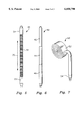
- FIG. 1 is a side elevational view of a liquid sampler tube of the prior art
- FIG. 2 is a side elevational, partially sectional view depicting use of a liquid sampler tube in sampling well water;
- FIG. 3 is a side elevational view depicting use of a liquid sampler tube to sample liquid carried in a tanker truck;
- FIG. 4 is a perspective view depicting use of a liquid sampler tube to sample liquid contained in a fifty gallon drum;
- FIG. 5 is a side elevational view depicting a first embodiment of the novel adjustable length liquid sampler tube
- FIG. 6 is a side elevational view depicting a second embodiment of the novel adjustable length liquid sampler tube.
- FIG. 7 is a perspective view depicting a third embodiment of the novel adjustable length liquid sampler tube.
- Liquid sampler tube 10 includes a handle means 12 in the form of a loop at its upper or proximal end, an elongate hollow main body 14 of cylindrical construction for receiving liquid, and a check valve means including a free floating ball 16 in its lower or distal free end. Ball 16 floats freely to allow liquid to enter into main body 14 at said lowermost end when liquid sampler tube 10 is being lowered into a body of liquid, but said ball 16 seats against a valve seat and prevents liquid from flowing out of main body 14 when said main body is lifted from said body of liquid. Graduation marks 18 enable the user to measure the amount of liquid collected within main body 14.
- a rope or other suitable connection means is secured to handle means 12 if liquid sampler tube 10 is to be lowered to a depth that exceeds the length of main body 14.
- liquid sampler 10 One common use of liquid sampler 10 is to sample water 20 (or other liquid) in a well 22 as depicted in FIG. 2.
- liquid sampler tube 10 Another common use is to retrieve a sample of gasoline, kerosene, or the like from the hold of a tanker truck as depicted in FIG. 3.
- the fixed length of industry standard liquid sampler tube 10 may be manufactured to any manageable length as desired.
- Liquid sampler tube 10 can also be used to sample liquid held in the hold of a ship, not shown, and in many other unillustrated applications.
- FIG. 4 depicts a conventional liquid sampler 10 in use to sample liquid contained within a drum, such as a fifty gallon drum, or the like.
- main body 32 has an accordion-like construction as depicted so that it can be foreshortened when said accordion-like section is compressed, i.e., when the opposite ends of liquid sampler tube 10 are manually displaced toward one another. This enables it to be reduced in length to less than fifty percent (50%) of its initial length so that at least twice as many liquid sampler tubes may be stored and shipped in the same space as the liquid sampler tubes of the prior art.
- the accordion-like construction also facilitates returning the liquid sampler to its initial, unshortened length so that it can be used in the conventional way in wells, holds, drums, and the like.
- elongate main body 32 at each end thereof is not provided with the annular folds that collectively provide the accordion-effect.
- Said unaltered spaces are denoted 31 and 33 respectively.
- Tubular spaces 31, 33 provide gripping surfaces where a user may grasp liquid sampler 10 at its opposite ends by the hands to shorten it or to lengthen it, as suggested by double-headed arrow 35 in FIG. 5.
- FIG. 6 Another feasible way to shorten liquid sampler tube 10 for storage or shipping purposes is denoted 40 as a whole in FIG. 6.
- upper section 42 is slideingly received into middle section 44 and said middle section 44 is slideingly received into lower section 46.
- main body 52 is formed of a flat, flexible hose material that can be rolled into a rolled configuration as depicted. This also greatly reduces the amount of space occupied by liquid sampler tube 50 when it is in storage or in transport. Liquid flowing past ball valve 16 restores main body 52 to its initial configuration when liquid sampler tube 50 is unrolled and in use.
- a weight means 54 of predetermined mass may be added to elongate main body 52 near its lowermost end to ensure straightening of the flexible hose material as it is lowered into a body of water.
Landscapes
- Life Sciences & Earth Sciences (AREA)
- Hydrology & Water Resources (AREA)
- Physics & Mathematics (AREA)
- Health & Medical Sciences (AREA)
- Chemical & Material Sciences (AREA)
- Analytical Chemistry (AREA)
- Biochemistry (AREA)
- General Health & Medical Sciences (AREA)
- General Physics & Mathematics (AREA)
- Immunology (AREA)
- Pathology (AREA)
- Sampling And Sample Adjustment (AREA)
Abstract
A liquid sampler tube of elongate, cylindrical construction has an accordion fold formed along a predetermined extent of its main body so that the liquid sampler tube can be shortened when in storage or in transport and returned to its initial length when ready for use. In a second embodiment, a telescoping construction supplants the accordion fold. In a third embodiment, the elongate main body is formed of a flexible, flat hose material so that it can be rolled into a rolled configuration for storage or transport and unrolled when ready for use. The shortening of the liquid sampler tube enables a greater number of liquid sampler tubes to occupy a given space relative to the number of liquid sampler tubes of standard, unshortened length.
Description
1. Field of the Invention
This invention relates, generally, to tools used to collect liquid samples for testing purposes. More particularly, it relates to a liquid sampler tube having an adjustable length so that it can be shortened to save space when in storage or in transport.
2. Description of the Prior Art
Liquid sampler tubes are elongate, cylindrical tubes that are lowered into wells or other liquid reservoirs to collect liquid samples therefrom. A check valve in the lowermost end of the tube opens automatically to allow liquid to flow into the hollow interior of the tube as it is being lowered into liquid held in a well or other reservoir. The check valve closes when the tube is lifted or displaced upwardly as it is removed from the body of liquid, thereby trapping a predetermined amount of liquid within said hollow interior. The liquid is then subjected to chemical analysis or other tests for a wide variety of purposes.
Liquid sampler tubes are typically made of plastic and are mass produceable so they are relatively inexpensive to manufacture. However, due to their elongate, cylindrical shape, they are not particularly inexpensive to store and to transport.
What is needed, then, is a way to reduce the storage and transportation costs associated with liquid sampler tubes.
However, it was not obvious to those of ordinary skill in this art how the needed improvements could be provided, in view of the art considered as a whole at the time the present invention was made.
The long-standing but heretofore unfulfilled need for an innovation that overcomes the limitations of the prior art is now met by a new, useful, and nonobvious invention. The present invention is a liquid sampler tube that includes an elongate, hollow tube having a handle means at a first end thereof, a check valve means at a second end thereof, and an elongate main body therebetween of predetermined initial length. A shortening means is provided for selectively reducing the predetermined initial length to a shortened length for storage or transportation purposes and for selectively increasing the shortened length to restore it to the initial predetermined length for use. Accordingly, a predetermined amount of space holds an increased number of shortened liquid sampler tubes relative to the amount of space required to hold an equal number of liquid sampler tubes having said unshortened predetermined initial length.
In a first embodiment, the shortening means is an accordion-fold formed in the elongate main body of the liquid sampler tube along its extent.
In a second embodiment, the shortening means is a telescoping means.
In a third embodiment, the shortening means is provided by forming the elongate main body of a flexible, flat hose material and rolling said flexible, flat hose material into a rolled configuration.
It is a primary object of this invention to provide an adjustable length liquid sampler tube that, when its length has been shortened, occupies less space than the liquid sampler tubes heretofore known, thereby reducing storage and transportation costs.
Another object is to provide a liquid sampler tube that is easily foreshortened in length and that is just as easily restored to its initial length.
These and other important objects, features, and advantages of the invention will become apparent as this description proceeds.
The invention accordingly comprises the features of construction, combination of elements and arrangement of parts that will be exemplified in the construction hereinafter set forth, and the scope of the invention will be indicated in the claims.
For a fuller understanding of the nature and objects of the invention, reference should be made to the following detailed description, taken in connection with the accompanying drawings, in which:
FIG. 1 is a side elevational view of a liquid sampler tube of the prior art;
FIG. 2 is a side elevational, partially sectional view depicting use of a liquid sampler tube in sampling well water;
FIG. 3 is a side elevational view depicting use of a liquid sampler tube to sample liquid carried in a tanker truck;
FIG. 4 is a perspective view depicting use of a liquid sampler tube to sample liquid contained in a fifty gallon drum;
FIG. 5 is a side elevational view depicting a first embodiment of the novel adjustable length liquid sampler tube;
FIG. 6 is a side elevational view depicting a second embodiment of the novel adjustable length liquid sampler tube; and
FIG. 7 is a perspective view depicting a third embodiment of the novel adjustable length liquid sampler tube.
Referring now to FIG. 1, it will there be seen that an industry standard liquid sampler tube is denoted as a whole by the reference numeral 10. Liquid sampler tube 10 includes a handle means 12 in the form of a loop at its upper or proximal end, an elongate hollow main body 14 of cylindrical construction for receiving liquid, and a check valve means including a free floating ball 16 in its lower or distal free end. Ball 16 floats freely to allow liquid to enter into main body 14 at said lowermost end when liquid sampler tube 10 is being lowered into a body of liquid, but said ball 16 seats against a valve seat and prevents liquid from flowing out of main body 14 when said main body is lifted from said body of liquid. Graduation marks 18 enable the user to measure the amount of liquid collected within main body 14.
A rope or other suitable connection means, not shown, is secured to handle means 12 if liquid sampler tube 10 is to be lowered to a depth that exceeds the length of main body 14.
One common use of liquid sampler 10 is to sample water 20 (or other liquid) in a well 22 as depicted in FIG. 2.
Another common use is to retrieve a sample of gasoline, kerosene, or the like from the hold of a tanker truck as depicted in FIG. 3. Note that the fixed length of industry standard liquid sampler tube 10 may be manufactured to any manageable length as desired. Liquid sampler tube 10 can also be used to sample liquid held in the hold of a ship, not shown, and in many other unillustrated applications.
FIG. 4 depicts a conventional liquid sampler 10 in use to sample liquid contained within a drum, such as a fifty gallon drum, or the like.
The preferred embodiment of the invention is depicted in FIG. 5 and is denoted 30 as a whole. A major percentage of main body 32 has an accordion-like construction as depicted so that it can be foreshortened when said accordion-like section is compressed, i.e., when the opposite ends of liquid sampler tube 10 are manually displaced toward one another. This enables it to be reduced in length to less than fifty percent (50%) of its initial length so that at least twice as many liquid sampler tubes may be stored and shipped in the same space as the liquid sampler tubes of the prior art.
The accordion-like construction also facilitates returning the liquid sampler to its initial, unshortened length so that it can be used in the conventional way in wells, holds, drums, and the like.
Note that about four inches or so of elongate main body 32 at each end thereof is not provided with the annular folds that collectively provide the accordion-effect. Said unaltered spaces are denoted 31 and 33 respectively. Tubular spaces 31, 33 provide gripping surfaces where a user may grasp liquid sampler 10 at its opposite ends by the hands to shorten it or to lengthen it, as suggested by double-headed arrow 35 in FIG. 5.
Another feasible way to shorten liquid sampler tube 10 for storage or shipping purposes is denoted 40 as a whole in FIG. 6. In this telescoping design, upper section 42 is slideingly received into middle section 44 and said middle section 44 is slideingly received into lower section 46. This reduces the overall length of liquid sampler tube 40 to about one-third its initial length for storage and shipping purposes. Like the preferred embodiment, it is a simple matter to restore liquid sampler tube 40 to its initial length to prepare it for use.
A third embodiment, denoted 50 as a whole, is depicted in FIG. 7. In this embodiment, main body 52 is formed of a flat, flexible hose material that can be rolled into a rolled configuration as depicted. This also greatly reduces the amount of space occupied by liquid sampler tube 50 when it is in storage or in transport. Liquid flowing past ball valve 16 restores main body 52 to its initial configuration when liquid sampler tube 50 is unrolled and in use.
A weight means 54 of predetermined mass may be added to elongate main body 52 near its lowermost end to ensure straightening of the flexible hose material as it is lowered into a body of water.
This invention represents a major breakthrough in the art of liquid sampler tubes. Being drawn to a pioneering invention, the claims that follow are entitled, as a matter of law, to broad interpretation to protect the heart or essence of the invention from piracy.
It will thus be seen that the objects set forth above, and those made apparent from the foregoing description, are efficiently attained. Since certain changes may be made in the foregoing construction without departing from the scope of the invention, it is intended that all matters contained in the foregoing construction or shown in the accompanying drawings shall be interpreted as illustrative and not in a limiting sense.
It is also to be understood that the following claims are intended to cover all of the generic and specific features of the invention herein described, and all statements of the scope of the invention which, as a matter of language, might be said to fall therebetween.
Now that the invention has been described,
Claims (1)
1. A liquid sampler tube, comprising:
an elongate, hollow tube having a handle means at a first end thereof, a check valve means at a second end thereof, and an elongate main body therebetween having a predetermined length;
shortening means for selectively reducing said predetermined length to a shortened length and for selectively increasing said shortened length to said predetermined length, wherein said shortening means is an accordion-fold formed along the extent of said elongate main body;
whereby a predetermined amount of space holds an increased number of shortened liquid sampler tubes relative to an equal number of liquid sampler tubes having said predetermined length; and
whereby a liquid sampler tube of shortened length is restored to its predetermined length prior to use.
Priority Applications (1)
| Application Number | Priority Date | Filing Date | Title |
|---|---|---|---|
| US09/237,478 US6058790A (en) | 1999-01-26 | 1999-01-26 | Adjustable length sampler tube |
Applications Claiming Priority (1)
| Application Number | Priority Date | Filing Date | Title |
|---|---|---|---|
| US09/237,478 US6058790A (en) | 1999-01-26 | 1999-01-26 | Adjustable length sampler tube |
Publications (1)
| Publication Number | Publication Date |
|---|---|
| US6058790A true US6058790A (en) | 2000-05-09 |
Family
ID=22893889
Family Applications (1)
| Application Number | Title | Priority Date | Filing Date |
|---|---|---|---|
| US09/237,478 Expired - Fee Related US6058790A (en) | 1999-01-26 | 1999-01-26 | Adjustable length sampler tube |
Country Status (1)
| Country | Link |
|---|---|
| US (1) | US6058790A (en) |
Cited By (3)
| Publication number | Priority date | Publication date | Assignee | Title |
|---|---|---|---|---|
| CN107131190A (en) * | 2017-07-11 | 2017-09-05 | 广东工业大学 | A kind of scalable sampling device |
| DE102016124857A1 (en) * | 2016-12-19 | 2018-06-21 | Technische Universität Darmstadt | Device for taking a water sample and a method for determining a distribution of the water content |
| CN110715825A (en) * | 2018-07-12 | 2020-01-21 | 四川赛恩思仪器有限公司 | Material detector analysis sampling device |
Citations (7)
| Publication number | Priority date | Publication date | Assignee | Title |
|---|---|---|---|---|
| US164451A (en) * | 1875-06-15 | Improvement in liquor testers, filterers, and emptiers combined | ||
| US293423A (en) * | 1884-02-12 | Paul contact | ||
| US4338826A (en) * | 1980-09-11 | 1982-07-13 | Air Test Labs, Inc. | Sampling apparatus |
| US4610171A (en) * | 1985-04-26 | 1986-09-09 | Nason Frederic L | Urinanalysis vial |
| US5507194A (en) * | 1993-10-06 | 1996-04-16 | Norton Performance Plastics Corporation | Disposable bailer |
| US5597966A (en) * | 1995-06-01 | 1997-01-28 | Timmons; Robert D. | Fluid sampling device |
| US5902940A (en) * | 1997-09-12 | 1999-05-11 | Applied Biogenics, Inc. | Disposable fluid sampling apparatus or bailer |
-
1999
- 1999-01-26 US US09/237,478 patent/US6058790A/en not_active Expired - Fee Related
Patent Citations (7)
| Publication number | Priority date | Publication date | Assignee | Title |
|---|---|---|---|---|
| US164451A (en) * | 1875-06-15 | Improvement in liquor testers, filterers, and emptiers combined | ||
| US293423A (en) * | 1884-02-12 | Paul contact | ||
| US4338826A (en) * | 1980-09-11 | 1982-07-13 | Air Test Labs, Inc. | Sampling apparatus |
| US4610171A (en) * | 1985-04-26 | 1986-09-09 | Nason Frederic L | Urinanalysis vial |
| US5507194A (en) * | 1993-10-06 | 1996-04-16 | Norton Performance Plastics Corporation | Disposable bailer |
| US5597966A (en) * | 1995-06-01 | 1997-01-28 | Timmons; Robert D. | Fluid sampling device |
| US5902940A (en) * | 1997-09-12 | 1999-05-11 | Applied Biogenics, Inc. | Disposable fluid sampling apparatus or bailer |
Cited By (4)
| Publication number | Priority date | Publication date | Assignee | Title |
|---|---|---|---|---|
| DE102016124857A1 (en) * | 2016-12-19 | 2018-06-21 | Technische Universität Darmstadt | Device for taking a water sample and a method for determining a distribution of the water content |
| CN107131190A (en) * | 2017-07-11 | 2017-09-05 | 广东工业大学 | A kind of scalable sampling device |
| CN107131190B (en) * | 2017-07-11 | 2023-02-07 | 广东工业大学 | Scalable sample device |
| CN110715825A (en) * | 2018-07-12 | 2020-01-21 | 四川赛恩思仪器有限公司 | Material detector analysis sampling device |
Similar Documents
| Publication | Publication Date | Title |
|---|---|---|
| US7574912B2 (en) | Collapsible liquid level measurement device with attachment | |
| US8789549B1 (en) | Portable canopy anchoring device and system | |
| US6058790A (en) | Adjustable length sampler tube | |
| DE3540768C1 (en) | Method and device for determining and displaying the amount of a liquid or solid storage item | |
| US20040040972A1 (en) | Collapsible beverage container and method therefor | |
| US4760747A (en) | Liquid sampling and measuring device | |
| US20170000099A1 (en) | Device and method of use for measuring fish | |
| US4141251A (en) | Pipetting device | |
| KR20190115269A (en) | Flexible sampler for groundwater | |
| EP1336533A3 (en) | Holder for a beverage container | |
| CN207439727U (en) | A kind of geotome | |
| US4869371A (en) | Pump components for building pump, and methods of constructing and using same | |
| US8959687B2 (en) | String line multipurpose tool | |
| KR101585172B1 (en) | Water sampling device | |
| US1527463A (en) | Joint adapter for fishing rods | |
| US5902940A (en) | Disposable fluid sampling apparatus or bailer | |
| US7000491B1 (en) | Aqueous vertical sampler | |
| US7353721B2 (en) | Fluid sampling device | |
| US7441472B2 (en) | Method and device for sampling fluids | |
| RU176043U1 (en) | MECHANIZED SAMPLER OF BULK MATERIALS | |
| CN212932042U (en) | Portable environment monitoring equipment | |
| CN214749170U (en) | Water multilayer sampling device for water quality testing | |
| CN221405658U (en) | Portable equipment for detecting heavy metal components in seawater | |
| Murphy et al. | Standardized sampling protocol for verifying mid-ocean ballast water exchange | |
| WO1994012817A1 (en) | Relief valve |
Legal Events
| Date | Code | Title | Description |
|---|---|---|---|
| REMI | Maintenance fee reminder mailed | ||
| LAPS | Lapse for failure to pay maintenance fees | ||
| FP | Lapsed due to failure to pay maintenance fee |
Effective date: 20040509 |
|
| STCH | Information on status: patent discontinuation |
Free format text: PATENT EXPIRED DUE TO NONPAYMENT OF MAINTENANCE FEES UNDER 37 CFR 1.362 |