US6058089A - External floppy drive with secure storage of a cable and connector for connecting to a computer system - Google Patents
External floppy drive with secure storage of a cable and connector for connecting to a computer system Download PDFInfo
- Publication number
- US6058089A US6058089A US08/370,939 US37093995A US6058089A US 6058089 A US6058089 A US 6058089A US 37093995 A US37093995 A US 37093995A US 6058089 A US6058089 A US 6058089A
- Authority
- US
- United States
- Prior art keywords
- peripheral device
- external peripheral
- electrical connector
- cable
- side edge
- Prior art date
- Legal status (The legal status is an assumption and is not a legal conclusion. Google has not performed a legal analysis and makes no representation as to the accuracy of the status listed.)
- Expired - Lifetime
Links
- 230000002093 peripheral effect Effects 0.000 claims abstract description 55
- 238000005452 bending Methods 0.000 claims description 3
- 238000013500 data storage Methods 0.000 description 2
- 238000012986 modification Methods 0.000 description 2
- 230000004048 modification Effects 0.000 description 2
- 230000004075 alteration Effects 0.000 description 1
- 230000000694 effects Effects 0.000 description 1
Images

Classifications
-
- H—ELECTRICITY
- H05—ELECTRIC TECHNIQUES NOT OTHERWISE PROVIDED FOR
- H05K—PRINTED CIRCUITS; CASINGS OR CONSTRUCTIONAL DETAILS OF ELECTRIC APPARATUS; MANUFACTURE OF ASSEMBLAGES OF ELECTRICAL COMPONENTS
- H05K5/00—Casings, cabinets or drawers for electric apparatus
- H05K5/02—Details
- H05K5/0256—Details of interchangeable modules or receptacles therefor, e.g. cartridge mechanisms
- H05K5/026—Details of interchangeable modules or receptacles therefor, e.g. cartridge mechanisms having standardized interfaces
- H05K5/0265—Details of interchangeable modules or receptacles therefor, e.g. cartridge mechanisms having standardized interfaces of PCMCIA type
- H05K5/0273—Details of interchangeable modules or receptacles therefor, e.g. cartridge mechanisms having standardized interfaces of PCMCIA type having extensions for peripherals, e.g. LAN, antennas
-
- G—PHYSICS
- G11—INFORMATION STORAGE
- G11B—INFORMATION STORAGE BASED ON RELATIVE MOVEMENT BETWEEN RECORD CARRIER AND TRANSDUCER
- G11B33/00—Constructional parts, details or accessories not provided for in the other groups of this subclass
- G11B33/02—Cabinets; Cases; Stands; Disposition of apparatus therein or thereon
- G11B33/022—Cases
- G11B33/025—Portable cases
Definitions
- This invention relates to external peripheral devices for personal computer systems. More specifically, this invention relates to external peripheral devices having a cable and a connector for connecting to a personal computer system.
- These external floppy drives are typically connected to the subnotebook by a cable to a special connector located on an external surface of the subnotebook.
- This connector may be a specially designated connector, or it may be a standard connector, such as a parallel or serial port that can double as the interface for the external floppy drive.
- An external floppy drive usually requires a cable to connect to the computer system.
- This cable if it is too long, can be rather unwieldy and difficult to manage when storing the external drive in a small case or just when carrying the device around. In fact, the dangling cable can be quite an annoyance.
- Some users may wrap the cable around the floppy drive, itself, but this means of storing the cable can be just a unwieldy as leaving the cable free to dangle wherever, since the connector at the end of the cable is still loose. If the cable, on the other hand, is too short, it may be difficult to position the drive in a usable place beside the computer during use. Thus, a need has arisen for some means to store the cable and the connector in an unobtrusive manner.
- An external peripheral device has a cable wrap member around which the flexible cable is wrapped during storage of the device. Additionally, the external peripheral device has a connector holder for securely holding the connector.
- the connector is preferably a PCMCIA connector card, but it is conceivable that other connectors could be used with this invention.
- the cable wrap member protrudes from the rear end of the external peripheral device, and the flexible cable wraps around this protrusion.
- Flange members attach to the free end of the protrusion, so the flexible cable is held in place on the protrusion by the flange members and the housing of the external peripheral device.
- the connector holder is a lowered space in the top surface of the external device into which the PCMCIA connector card fits snugly. Small lips on the top surface of the external device protrude out over the connector holder space in order to hold the PCMCIA connector card in place.
- a spring on one side of the lowered space presses the connector card up against the other side of the lowered space. This spring, in combination with the small lips, hold the PCMCIA connector card securely in the connector holder space.
- FIG. 1 is a perspective view of an external floppy drive according to the present invention
- FIG. 2 is a rear view thereof with the flexible cable and PCMCIA connector card securely stored;
- FIG. 3 is a side view thereof.
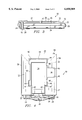
- FIG. 4 is a top view thereof.
- an external floppy disk drive 10 is shown with a housing 12 connected to a PCMCIA connector card 14 by a flexible cable 16.
- a floppy disk bay door 18, a floppy disk ejector button 20 and a floppy disk drive activity LED 21 are located on the front face 22 of the housing 12.
- other external peripherals could include an external CD ROM drive.
- the floppy drive bay door 18 would be replaced with a CD ROM drive bay door.
- Another external peripheral could include an external hard drive.
- the housing 12 has a cable wrap member 24 that protrudes out of the rear face 26 of the housing 12.
- Flanges 28 connect to the free end of the protruding cable wrap member 24.
- a cable notch 30 in the middle of the protruding cable wrap member 24 receives the flexible cable 16 (see FIGS. 2-4).
- the housing 12 also has a top surface 32 that curves upwardly and inwardly from the front 22 and side faces 34, 36.
- a flat lowered space 38 that is only slightly larger than the dimensions of the PCMCIA connector card 14.
- the lowered space 38 is bounded by walls 40, 42, 43, 44, 45 and 46.
- Most of wall 42 is open to permit lowered space 38 to extend to the rear face 26 of the housing 12 bounded by walls 43.
- part of wall 44 is open to permit lowered space 38 to extend almost to side face 34 bounded by walls 45.
- Two small lips 48 extend from the top surface 32 of the housing 12 above the wall 44 out over the lowered space 38.
- another lip 50 extends from the top surface 32 of the housing 12 above the wall 40 out over the lowered space 38.
- Springs 52 protrude out through an opening 54 in wall 40 under lip 50.
- the PCMCIA connector card 14 has two rows of small connector pin holes 56 arrayed on its front surface 58 for connection to matching pins on a connector slot in a computer system (not shown).
- the flexible cable 16 wraps around the cable wrap member 24 as seen in FIGS. 2-4.
- the drawings show the cable 16 inserted in the cable notch 30 near the housing end of the cable 16, but the cable 16 could be held in the cable notch 30 near the PCMCIA connector end of the cable 16 according to the user's preference. Either way, the flexible cable 16 is held in cable notch 30 to prevent unnecessary bending stresses on the joint between the cable 16 and either the housing 12 or the PCMCIA connector card 14.
- the PCMCIA connector card 14 fits into the lowered space 38 as seen in FIG. 4.
- the opening in wall 42 that permits the lowered space 38 to extend to the rear face 26 also permits an access for the flexible cable 16.
- Lips 48 and 50 hold the PCMCIA connector card 14 down, and springs 52 press the PCMCIA connector card against wall 44. Together, the lips 48 and 50 and the springs 52 hold the PCMCIA connector card 14 securely in place in the lowered space 38 such that the lips 48 and 50, the walls 40, 42, 43, 44, 45 and 46, the springs 52 and the lowered space 38 form a PCMCIA connector card holder.
- the combination of the cable 16 wrapped around the cable wrap member 24 and the PCMCIA connector card 14 held in the connector card holder provides a convenient way to secure the entire housing/cable/connector unit for easy storage and transportation.
- the opening in wall 44 that permits the lowered space 38 to extend almost to the side face 34 also permits the user to use a finger to push the PCMCIA connector card 14 in the direction of arrow A (FIG. 2) against the springs 52.
- the side of the PCMCIA connector card 14 will clear the lips 48, so that the user can then lift and rotate the PCMCIA connector card 14 in the direction of arrow B, thus removing the connector 14 from the connector holder.
- Replacing the connector 14 in the connector holder is done in simply the opposite manner.
Landscapes
- Engineering & Computer Science (AREA)
- Microelectronics & Electronic Packaging (AREA)
- Details Of Connecting Devices For Male And Female Coupling (AREA)
Abstract
Description
Claims (18)
Priority Applications (1)
| Application Number | Priority Date | Filing Date | Title |
|---|---|---|---|
| US08/370,939 US6058089A (en) | 1993-01-27 | 1995-01-10 | External floppy drive with secure storage of a cable and connector for connecting to a computer system |
Applications Claiming Priority (4)
| Application Number | Priority Date | Filing Date | Title |
|---|---|---|---|
| US1002093A | 1993-01-27 | 1993-01-27 | |
| US29/018,030 USD366472S (en) | 1994-01-27 | 1994-01-27 | External floppy disk drive for a notebook personal computer |
| US18948794A | 1994-01-31 | 1994-01-31 | |
| US08/370,939 US6058089A (en) | 1993-01-27 | 1995-01-10 | External floppy drive with secure storage of a cable and connector for connecting to a computer system |
Related Parent Applications (3)
| Application Number | Title | Priority Date | Filing Date |
|---|---|---|---|
| US1002093A Continuation-In-Part | 1993-01-27 | 1993-01-27 | |
| US29018030 Continuation-In-Part | 1994-01-27 | ||
| US18948794A Continuation-In-Part | 1993-01-27 | 1994-01-31 |
Publications (1)
| Publication Number | Publication Date |
|---|---|
| US6058089A true US6058089A (en) | 2000-05-02 |
Family
ID=27359133
Family Applications (1)
| Application Number | Title | Priority Date | Filing Date |
|---|---|---|---|
| US08/370,939 Expired - Lifetime US6058089A (en) | 1993-01-27 | 1995-01-10 | External floppy drive with secure storage of a cable and connector for connecting to a computer system |
Country Status (1)
| Country | Link |
|---|---|
| US (1) | US6058089A (en) |
Cited By (19)
| Publication number | Priority date | Publication date | Assignee | Title |
|---|---|---|---|---|
| US6320835B1 (en) * | 1997-11-04 | 2001-11-20 | Teac Corporation | Disk drive device having a housing and a flexible cable connected between the housing and a disk tray |
| US6334788B1 (en) * | 1999-05-14 | 2002-01-01 | Sony Corporation | Electronic apparatus for reproducing data |
| US6386908B2 (en) * | 1997-09-19 | 2002-05-14 | Sony Corporation | Electronic device |
| USD487460S1 (en) | 2002-12-02 | 2004-03-09 | Lite On It Corporation | External slot-in optical disk drive |
| US6705891B1 (en) * | 2002-10-24 | 2004-03-16 | Hon Hai Precision Ind. Co., Ltd. | Case for portable storage peripheral equipment |
| US6722917B2 (en) * | 2002-02-01 | 2004-04-20 | Yea Yen Huang | USB hub |
| US20040105230A1 (en) * | 2002-11-29 | 2004-06-03 | Yi-Sheng Lin | Case for portable storage peripheral equipment having cable assembly with strain relief |
| US20040139279A1 (en) * | 2002-12-30 | 2004-07-15 | Freecom Technologies B.V. | Memory device |
| US6931474B1 (en) | 1999-09-23 | 2005-08-16 | Intel Corporation | Dual-function computing system having instant-on mode of operation |
| DE102004004739A1 (en) * | 2004-01-30 | 2005-08-18 | Robert Bosch Gmbh | Contact arrangement for connecting an electronic component to a substrate having a defined plug device which can be removed and connected to the substrate |
| US7098899B1 (en) * | 1999-09-21 | 2006-08-29 | Intel Corporation | Dual form low power, instant on and high performance, non-instant on computing device |
| US20070218731A1 (en) * | 2006-03-20 | 2007-09-20 | Fujitsu Limited | Electronic apparatus |
| US20070291449A1 (en) * | 2006-06-16 | 2007-12-20 | Asustek Computer Inc. | OTG type storage device and notebook computer using the same |
| US20110136355A1 (en) * | 2009-12-09 | 2011-06-09 | Michael Delpier | Port Attached To Flexible Mount |
| US20110216499A1 (en) * | 2010-03-03 | 2011-09-08 | Andrew Lee | Computer hot-plug structure |
| US20120170176A1 (en) * | 2011-01-04 | 2012-07-05 | Nokia Corporation | Method and Apparatus for an Electronic Device |
| US20120262899A1 (en) * | 2009-06-25 | 2012-10-18 | Nifco Inc. | Cable holder for mounting on vehicle |
| USD702692S1 (en) * | 2011-11-23 | 2014-04-15 | Digital Hard Copy | Card for holding a digital storage medium |
| USD702693S1 (en) * | 2011-11-23 | 2014-04-15 | Digital Hard Copy | Digital storage medium card |
Citations (3)
| Publication number | Priority date | Publication date | Assignee | Title |
|---|---|---|---|---|
| US5033474A (en) * | 1990-01-05 | 1991-07-23 | Buddy Systems, Inc. | ECG cable storage means in a personal health monitor |
| US5132871A (en) * | 1989-09-11 | 1992-07-21 | Poqet Computer Corporation | Battery powered disk drive system having a smart connector for a portable computer |
| US5153817A (en) * | 1990-02-09 | 1992-10-06 | Kabushiki Kaisha Toshiba | Electronic apparatus system including an expansion device removably connected to a removable battery pack |
-
1995
- 1995-01-10 US US08/370,939 patent/US6058089A/en not_active Expired - Lifetime
Patent Citations (3)
| Publication number | Priority date | Publication date | Assignee | Title |
|---|---|---|---|---|
| US5132871A (en) * | 1989-09-11 | 1992-07-21 | Poqet Computer Corporation | Battery powered disk drive system having a smart connector for a portable computer |
| US5033474A (en) * | 1990-01-05 | 1991-07-23 | Buddy Systems, Inc. | ECG cable storage means in a personal health monitor |
| US5153817A (en) * | 1990-02-09 | 1992-10-06 | Kabushiki Kaisha Toshiba | Electronic apparatus system including an expansion device removably connected to a removable battery pack |
Cited By (25)
| Publication number | Priority date | Publication date | Assignee | Title |
|---|---|---|---|---|
| US6386908B2 (en) * | 1997-09-19 | 2002-05-14 | Sony Corporation | Electronic device |
| US6320835B1 (en) * | 1997-11-04 | 2001-11-20 | Teac Corporation | Disk drive device having a housing and a flexible cable connected between the housing and a disk tray |
| US6334788B1 (en) * | 1999-05-14 | 2002-01-01 | Sony Corporation | Electronic apparatus for reproducing data |
| US7098899B1 (en) * | 1999-09-21 | 2006-08-29 | Intel Corporation | Dual form low power, instant on and high performance, non-instant on computing device |
| US7096309B2 (en) | 1999-09-23 | 2006-08-22 | Intel Corporation | Computing device capable of instant-on and non-instant on modes of operation |
| US6931474B1 (en) | 1999-09-23 | 2005-08-16 | Intel Corporation | Dual-function computing system having instant-on mode of operation |
| US6722917B2 (en) * | 2002-02-01 | 2004-04-20 | Yea Yen Huang | USB hub |
| US6705891B1 (en) * | 2002-10-24 | 2004-03-16 | Hon Hai Precision Ind. Co., Ltd. | Case for portable storage peripheral equipment |
| US20040105230A1 (en) * | 2002-11-29 | 2004-06-03 | Yi-Sheng Lin | Case for portable storage peripheral equipment having cable assembly with strain relief |
| USD487460S1 (en) | 2002-12-02 | 2004-03-09 | Lite On It Corporation | External slot-in optical disk drive |
| US7136288B2 (en) * | 2002-12-30 | 2006-11-14 | Freecom Technologies B.V. | Memory device |
| US20040139279A1 (en) * | 2002-12-30 | 2004-07-15 | Freecom Technologies B.V. | Memory device |
| DE102004004739A1 (en) * | 2004-01-30 | 2005-08-18 | Robert Bosch Gmbh | Contact arrangement for connecting an electronic component to a substrate having a defined plug device which can be removed and connected to the substrate |
| US20070218731A1 (en) * | 2006-03-20 | 2007-09-20 | Fujitsu Limited | Electronic apparatus |
| US7393241B2 (en) * | 2006-03-20 | 2008-07-01 | Fujitsu Limited | Electronic apparatus |
| US20070291449A1 (en) * | 2006-06-16 | 2007-12-20 | Asustek Computer Inc. | OTG type storage device and notebook computer using the same |
| US20120262899A1 (en) * | 2009-06-25 | 2012-10-18 | Nifco Inc. | Cable holder for mounting on vehicle |
| US8079867B2 (en) * | 2009-12-09 | 2011-12-20 | Hewlett-Packard Development Company, L.P. | Port attached to flexible mount |
| US20110136355A1 (en) * | 2009-12-09 | 2011-06-09 | Michael Delpier | Port Attached To Flexible Mount |
| US20110216499A1 (en) * | 2010-03-03 | 2011-09-08 | Andrew Lee | Computer hot-plug structure |
| US8035962B2 (en) * | 2010-03-03 | 2011-10-11 | Antec, Inc. | Computer hot-plug structure |
| US20120170176A1 (en) * | 2011-01-04 | 2012-07-05 | Nokia Corporation | Method and Apparatus for an Electronic Device |
| US8767387B2 (en) * | 2011-01-04 | 2014-07-01 | Vertu Corporation Limited | Method and apparatus for an electronic device |
| USD702692S1 (en) * | 2011-11-23 | 2014-04-15 | Digital Hard Copy | Card for holding a digital storage medium |
| USD702693S1 (en) * | 2011-11-23 | 2014-04-15 | Digital Hard Copy | Digital storage medium card |
Similar Documents
| Publication | Publication Date | Title |
|---|---|---|
| US6058089A (en) | External floppy drive with secure storage of a cable and connector for connecting to a computer system | |
| US5734551A (en) | Method to install SIMMs without causing discomfort to the user | |
| US7172460B2 (en) | Universal serial bus connector with integral shell | |
| EP0811186B1 (en) | Modular pcmcia card | |
| CA2220380C (en) | An adapter base for receiving a cartridge memory | |
| US6222726B1 (en) | Portable personal computer with arrangement for connecting an expansion card to a socket therein | |
| US6285159B1 (en) | Portable computer usable with a specific battery pack or ordinary battery | |
| US6524137B1 (en) | Integral multiplex adapter card | |
| US20050213297A1 (en) | Extended peripheral battery pack for a tablet computer | |
| JP2000029583A (en) | Adapter for personal computer peripheral device | |
| US6386908B2 (en) | Electronic device | |
| US20040075977A1 (en) | USB memory receptacle of electronic device | |
| US5117378A (en) | Laptop computer with detachable interface card | |
| US20040026516A1 (en) | Combined flash memory card | |
| US6709278B2 (en) | Personal digital assistant with a foldable memory card adapter | |
| JPH10133776A (en) | Portable electronic devices | |
| US6390855B1 (en) | Expansion slot adapter for a palm held computer | |
| US20080009197A1 (en) | Memory card assembly | |
| US20060082963A1 (en) | USB drive mass storage device with means for holding memory cards not in use | |
| JP4921209B2 (en) | USB plug and USB device provided with the USB plug | |
| US10043114B2 (en) | Electronic device | |
| US6327154B1 (en) | Battery case for PCMCIA card modem with antenna | |
| US6058008A (en) | Insertion device for the hard disk drive of a portable computer | |
| JP2816318B2 (en) | Electronics | |
| JPH03175517A (en) | Small size computer with plug-in type memory unit for protecting data |
Legal Events
| Date | Code | Title | Description |
|---|---|---|---|
| AS | Assignment |
Owner name: COMPAQ COMPUTER CORPORATION, TEXAS Free format text: ASSIGNMENT OF ASSIGNORS INTEREST;ASSIGNORS:YOUENS, JOHN E.;NEGISHI, RYUICHI;OKADA, TORU;AND OTHERS;REEL/FRAME:007518/0885 Effective date: 19950110 |
|
| FEPP | Fee payment procedure |
Free format text: PAYOR NUMBER ASSIGNED (ORIGINAL EVENT CODE: ASPN); ENTITY STATUS OF PATENT OWNER: LARGE ENTITY |
|
| STCF | Information on status: patent grant |
Free format text: PATENTED CASE |
|
| AS | Assignment |
Owner name: COMPAQ INFORMATION TECHNOLOGIES GROUP, L.P., TEXAS Free format text: ASSIGNMENT OF ASSIGNORS INTEREST;ASSIGNOR:COMPAQ COMPUTER CORPORATION;REEL/FRAME:012418/0222 Effective date: 20010620 |
|
| FPAY | Fee payment |
Year of fee payment: 4 |
|
| AS | Assignment |
Owner name: HEWLETT-PACKARD DEVELOPMENT COMPANY, L.P., TEXAS Free format text: CHANGE OF NAME;ASSIGNOR:COMPAQ INFORMATION TECHNOLOGIES GROUP, LP;REEL/FRAME:015000/0305 Effective date: 20021001 |
|
| FPAY | Fee payment |
Year of fee payment: 8 |
|
| FPAY | Fee payment |
Year of fee payment: 12 |