US6051985A - Horizontal circuit drive analyzer and method of analyzing the horizontal circuit drive of a video display - Google Patents
Horizontal circuit drive analyzer and method of analyzing the horizontal circuit drive of a video display Download PDFInfo
- Publication number
- US6051985A US6051985A US09/102,110 US10211098A US6051985A US 6051985 A US6051985 A US 6051985A US 10211098 A US10211098 A US 10211098A US 6051985 A US6051985 A US 6051985A
- Authority
- US
- United States
- Prior art keywords
- output
- horizontal drive
- load
- base
- drive stage
- Prior art date
- Legal status (The legal status is an assumption and is not a legal conclusion. Google has not performed a legal analysis and makes no representation as to the accuracy of the status listed.)
- Expired - Fee Related
Links
Images
Classifications
-
- H—ELECTRICITY
- H04—ELECTRIC COMMUNICATION TECHNIQUE
- H04N—PICTORIAL COMMUNICATION, e.g. TELEVISION
- H04N17/00—Diagnosis, testing or measuring for television systems or their details
- H04N17/04—Diagnosis, testing or measuring for television systems or their details for receivers
Definitions
- the present invention relates to a method and instrument for analyzing the horizontal sweep circuit drive of a video display of the type used for television receivers and other CRT monitors, and it more particularly relates to a method for detecting an abnormal drive current to the horizontal sweep circuit of multifrequency video displays.
- Multifrequency video displays are adapted to operate through a range of horizontal frequencies, and the horizontal drive stage must produce a base current to the horizontal output transistor which is suitable for the current required for each frequency at which the display operates. Displays with a wide horizontal operating range frequently have horizontal drive stages which are capable of switching between two or more levels of base current to the horizontal output transistor (H.O.T.) so that it is lower at lower frequencies and higher at high frequencies.
- H.O.T. horizontal output transistor
- a lower base current is needed for lower frequencies because the H.O.T. conducts for longer periods of time at the lower frequencies thereby allowing a significantly higher collector current than would occur if the same collector current were applied at higher frequencies.
- Two methods are commonly employed in the driver stage to switch the current level to the base of the H.O.T.
- One method is to change the level of the primary current in the driver transformer by changing the primary resistor which is in series with the windings of the transformer.
- the second method is to switch a resistor in series with the output for the driver circuit and the base of the H.O.T.
- the H.O.T. will not provide the collector current which is normally required for proper operation of the display.
- the symptoms may not be detectable if the current is reduced only slightly, but more significant reductions will cause the collector current to become limited, thereby limiting the horizontal deflection.
- the efficiency of the H.O.T. is correspondingly reduced, and this will cause the H.O.T. to overheat and prematurely fail.
- the present invention is employed to test the horizontal drive stage of a cathode ray tube display where the horizontal drive stage has a drive output which is directed to the base of a H.O.T.
- the output from the horizontal drive circuit is disconnected from the base of the H.O.T. and is connected to the apparatus of the present invention such that the apparatus of the present invention will replace the load seen by the horizontal drive circuit.
- a load is connected between the output of the horizontal drive circuit and ground which simulates the load normally provided by the base of the H.O.T.
- a metering means such as a conventional voltage measuring circuit, is connected across the load to measure the output of the horizontal drive circuit, and the readings from the metering means are thereafter projected on a display.
- the H.O.T. is typically a conventional bipolar or MOSFET type transistor which operates as an on and off switch. To accommodate the requirements of such transistors, the horizontal drive stage output provides a square wave having positive and negative phases which alternately switch the H.O.T. between the on and off condition.
- the load which is attached to the output of the horizontal drive stage includes a resistor in series with a Schottky diode which permits the drive current output produced by the driver stage to flow through the resistor during only the positive cycle, thereby simulating the positive drive cycle provided to the base of the H.O.T.
- the voltage across the resistor is proportional to the positive current from the output of the horizontal drive circuit.
- the voltage across the resistor is amplified by a differential amplifier and converted to an average DC voltage by a low pass filter and then measured by a conventional voltage measuring circuit. The voltage measurement relative to the drive current is then shown on any suitable display.
- the invention further includes a protector switch circuit which monitors the collector of the H.O.T. to prevent damage to the horizontal output stage in the event the service technician did not disconnect the base of the H.O.T. from the output stage.
- the protector switch circuit also provides protection to the diode and the associated circuitry of the test instrument from spurious currents.
- a technician can monitor the voltage output from the drive stage to determine if the correct current capacity is available to the horizontal output circuit. If the current to the base of the H.O.T. is inadequate, the technician can then troubleshoot the defective drive circuit. Similarly, if the output shows variations in voltage to the drive stage, he can troubleshoot the driver circuit for intermittent driver problems.
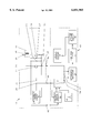
- the single drawing depicts a horizontal output circuit under test connected to a test instrument embodying the method of the present invention.
- the horizontal output stage 10 of a multifrequency cathode ray tube video display (the remaining portions of the display are not shown) includes a transformer 14, commonly referred to as a flyback transformer, one winding 15 of which is connected to a B+ power source 16.
- a yoke winding 18 is connected between ground and the opposite terminal of winding 15 of the transformer 14, and a retracing timing capacitor 20 and a dampener diode 22 are connected across the yoke 18.
- Connected to the junction between the yoke 18 and the winding 15 is the collector terminal 24 of a horizontal output transistor (H.O.T.) 26, the emitter terminal 28 of which is connected to ground 30.
- H.O.T. horizontal output transistor
- the horizontal drive circuit 32 of the device under test has a horizontal drive output 34 which is connected to the base 36 of the H.O.T (before testing performance).
- a test apparatus 40 in accordance with the present invention is provided.
- the test instrument 40 includes a first connector 42 for connection to the emitter terminal 28 of the H.O.T., a second connector 44 for connection to the horizontal driver output 34 and a third connector 46 for connection to the collector terminal 24 of the H.O.T.
- the test instrument 40 further includes a on/off actuator button 48 which is adapted to close a switch 50 thereby placing a current sensing resistor 52 in series with a diode 54, such as a Schottky diode, between the second connector 44 and the first connector 42.
- a protective circuit disable switch 56 is connected between the third connector 46 and the second connector 44.
- the protector current disable switch 56 is also connected to the switch 50 such that any spurious voltage detected between the collector 24 of the H.O.T. 26 and the drive stage output 34 will cause the protector circuit disable switch 56 to open switch 50 thereby disconnecting the resistor 52 and the diode 54 from the circuit.
- a differential amplifier 58 is connected across the current sensing resistor 52 to amplify the voltage across the resistor, and the current from the differential amplifier 58 is measured by a conventional voltage measuring circuit 60 after it is converted to DC voltage by a low pass filter 62. The voltage as measured by the circuit 60 is then shown on a suitable display 64 such as a liquid crystal display or the like.
- the method of the present invention is an active test and, therefore, power is then applied to the horizontal drive circuit after which the technician depresses the button 48 to close the switch 50 and holds the button 48 down until meaningful test readings are obtained. If there are no spurious currents detected between the connectors 42 and 46, the protection circuit will not disable the switch 50, and the resistor 52 and diode 54 will be connected between the horizontal drive output 34 and ground, thereby simulating the load imposed on the horizontal drive circuit by the base 36 of the H.O.T. The positive swing of the voltage from the horizontal drive output 34 is applied across the resistor 52 and this voltage is amplified by the differential amplifier 58. The output of the amplifier 58 is measured by the voltage measuring circuit 60 and shown on display 64.
- a technician can read the display 64 to determine the voltage relative to the drive current which the horizontal drive circuit applies to the base 36 of the H.O.T. and compare this voltage to specifications for the H.O.T. in a suitable reference manual. If the voltage differs from the proper operating requirements of the H.O.T. so as to be inadequate for the proper operation of the H.O.T., the technician can then troubleshoot the horizontal drive circuit 32.
Landscapes
- Engineering & Computer Science (AREA)
- Health & Medical Sciences (AREA)
- Biomedical Technology (AREA)
- General Health & Medical Sciences (AREA)
- Multimedia (AREA)
- Signal Processing (AREA)
- Testing, Inspecting, Measuring Of Stereoscopic Televisions And Televisions (AREA)
Abstract
Description
Claims (7)
Priority Applications (1)
| Application Number | Priority Date | Filing Date | Title |
|---|---|---|---|
| US09/102,110 US6051985A (en) | 1998-06-22 | 1998-06-22 | Horizontal circuit drive analyzer and method of analyzing the horizontal circuit drive of a video display |
Applications Claiming Priority (1)
| Application Number | Priority Date | Filing Date | Title |
|---|---|---|---|
| US09/102,110 US6051985A (en) | 1998-06-22 | 1998-06-22 | Horizontal circuit drive analyzer and method of analyzing the horizontal circuit drive of a video display |
Publications (1)
| Publication Number | Publication Date |
|---|---|
| US6051985A true US6051985A (en) | 2000-04-18 |
Family
ID=22288175
Family Applications (1)
| Application Number | Title | Priority Date | Filing Date |
|---|---|---|---|
| US09/102,110 Expired - Fee Related US6051985A (en) | 1998-06-22 | 1998-06-22 | Horizontal circuit drive analyzer and method of analyzing the horizontal circuit drive of a video display |
Country Status (1)
| Country | Link |
|---|---|
| US (1) | US6051985A (en) |
Cited By (1)
| Publication number | Priority date | Publication date | Assignee | Title |
|---|---|---|---|---|
| US20140184240A1 (en) * | 2012-12-30 | 2014-07-03 | Ching-Tsung Chen | Testing system with an isolated switching module |
Citations (5)
| Publication number | Priority date | Publication date | Assignee | Title |
|---|---|---|---|---|
| US3423631A (en) * | 1966-11-01 | 1969-01-21 | Gen Telephone & Elect | Horizontal deflection circuit |
| US3449623A (en) * | 1966-09-06 | 1969-06-10 | Rca Corp | Electron beam deflection circuit |
| US3622883A (en) * | 1965-08-18 | 1971-11-23 | Ibm | Pulsed current transistor beta tester having feedback to maintain emitter to collector current constant |
| US4301394A (en) * | 1979-11-28 | 1981-11-17 | Rca Corporation | Horizontal deflection circuit and power supply with regulation by horizontal output transistor turn-off delay control |
| US5357175A (en) * | 1992-04-10 | 1994-10-18 | Pioneer Electronic Corporation | Deflection and high voltage circuit |
-
1998
- 1998-06-22 US US09/102,110 patent/US6051985A/en not_active Expired - Fee Related
Patent Citations (5)
| Publication number | Priority date | Publication date | Assignee | Title |
|---|---|---|---|---|
| US3622883A (en) * | 1965-08-18 | 1971-11-23 | Ibm | Pulsed current transistor beta tester having feedback to maintain emitter to collector current constant |
| US3449623A (en) * | 1966-09-06 | 1969-06-10 | Rca Corp | Electron beam deflection circuit |
| US3423631A (en) * | 1966-11-01 | 1969-01-21 | Gen Telephone & Elect | Horizontal deflection circuit |
| US4301394A (en) * | 1979-11-28 | 1981-11-17 | Rca Corporation | Horizontal deflection circuit and power supply with regulation by horizontal output transistor turn-off delay control |
| US5357175A (en) * | 1992-04-10 | 1994-10-18 | Pioneer Electronic Corporation | Deflection and high voltage circuit |
Cited By (2)
| Publication number | Priority date | Publication date | Assignee | Title |
|---|---|---|---|---|
| US20140184240A1 (en) * | 2012-12-30 | 2014-07-03 | Ching-Tsung Chen | Testing system with an isolated switching module |
| US9244118B2 (en) * | 2012-12-30 | 2016-01-26 | Global Unichip Corp. | Testing system with an isolated switching module |
Similar Documents
| Publication | Publication Date | Title |
|---|---|---|
| US4719428A (en) | Storage battery condition tester utilizing low load current | |
| US7660776B1 (en) | System for automatically identifying power system type and identifying likely errors of wiring and connection | |
| US4728898A (en) | Method and apparatus for detecting and locating faults in an AC transmission line using two indicators | |
| US5705936A (en) | Method and apparatus for automatically testing semiconductor diodes | |
| CN104297622A (en) | Method and device for detecting defects of display panel | |
| US5029188A (en) | Apparatus for monitoring operation cycles of an electrically actuated device | |
| US10139454B2 (en) | Test device and alternating current power detection method of the same | |
| US3120758A (en) | Electrical testing equipment | |
| US6051985A (en) | Horizontal circuit drive analyzer and method of analyzing the horizontal circuit drive of a video display | |
| US3934194A (en) | Solid state flyback transformer checker | |
| US3784903A (en) | Leakage detector for determining possible shock hazards to humans | |
| US5469063A (en) | Method and apparatus for testing for a high voltage on the chassis of an electronic apparatus | |
| US20070188252A1 (en) | Detection device for detecting oscillator | |
| CN113391141B (en) | Noise testing device and testing method | |
| JP7246158B2 (en) | Coil reliability test equipment | |
| US5350979A (en) | Method of analyzing television circuits and instrumentation therefor | |
| JP3577912B2 (en) | Electronic circuit inspection equipment | |
| CN220933101U (en) | Fault circuit detection device | |
| US6069657A (en) | Television simulator for DST transformers | |
| US3588695A (en) | Condition monitoring apparatus | |
| US20170205449A1 (en) | Test device and alternating current power detection method of the same | |
| Zeng et al. | Research on Diagnosis and Treatment Methods of Common Malfunction in Electronic Circuits | |
| US11768242B1 (en) | Analyzer and method for regulations testing of a solar installation | |
| US20240110981A1 (en) | Analyzer and method for regulations testing of a solar installation | |
| CN211453766U (en) | Digital direct-current high-voltage microammeter data acquisition system |
Legal Events
| Date | Code | Title | Description |
|---|---|---|---|
| AS | Assignment |
Owner name: SENCORE INC., SOUTH DAKOTA Free format text: ASSIGNMENT OF ASSIGNORS INTEREST;ASSIGNORS:KROPUENSKE, GLEN;SCHLAG, SCOTT A.;REEL/FRAME:009273/0213 Effective date: 19980529 |
|
| REMI | Maintenance fee reminder mailed | ||
| FPAY | Fee payment |
Year of fee payment: 4 |
|
| SULP | Surcharge for late payment | ||
| FPAY | Fee payment |
Year of fee payment: 8 |
|
| AS | Assignment |
Owner name: US BANK NATIONAL ASSOCIATION, MINNESOTA Free format text: COLLATERAL ASSIGNMENT (PATENTS);ASSIGNOR:SENCORE, INC.;REEL/FRAME:022117/0833 Effective date: 20090115 |
|
| AS | Assignment |
Owner name: US BANK NATIONAL ASSOCIATION, AS ADMINISTRATIVE AG Free format text: CORRECTIVE ASSIGNMENT TO CORRECT THE ASSIGNEE AND CONVEYANCE PREVIOUSLY RECORDED ON REEL 022117 FRAME 0833;ASSIGNOR:SENCORE, INC.;REEL/FRAME:022266/0238 Effective date: 20090115 |
|
| REMI | Maintenance fee reminder mailed | ||
| LAPS | Lapse for failure to pay maintenance fees | ||
| LAPS | Lapse for failure to pay maintenance fees |
Free format text: PATENT EXPIRED FOR FAILURE TO PAY MAINTENANCE FEES (ORIGINAL EVENT CODE: EXP.); ENTITY STATUS OF PATENT OWNER: SMALL ENTITY |
|
| STCH | Information on status: patent discontinuation |
Free format text: PATENT EXPIRED DUE TO NONPAYMENT OF MAINTENANCE FEES UNDER 37 CFR 1.362 |
|
| FP | Lapsed due to failure to pay maintenance fee |
Effective date: 20120418 |
|
| AS | Assignment |
Owner name: SENCORE, INC., SOUTH DAKOTA Free format text: TERMINATION AND RELEASE OF SECURITY INTEREST IN PATENTS;ASSIGNOR:US BANK NATIONAL ASSOCIATION;REEL/FRAME:034587/0581 Effective date: 20141209 |