US6041525A - Footwear grinding apparatus with flanking bearing surfaces - Google Patents
Footwear grinding apparatus with flanking bearing surfaces Download PDFInfo
- Publication number
- US6041525A US6041525A US09/132,827 US13282798A US6041525A US 6041525 A US6041525 A US 6041525A US 13282798 A US13282798 A US 13282798A US 6041525 A US6041525 A US 6041525A
- Authority
- US
- United States
- Prior art keywords
- plate
- grind
- shoe
- set forth
- recess
- Prior art date
- Legal status (The legal status is an assumption and is not a legal conclusion. Google has not performed a legal analysis and makes no representation as to the accuracy of the status listed.)
- Expired - Fee Related
Links
Images


Classifications
-
- A—HUMAN NECESSITIES
- A43—FOOTWEAR
- A43B—CHARACTERISTIC FEATURES OF FOOTWEAR; PARTS OF FOOTWEAR
- A43B13/00—Soles; Sole-and-heel integral units
- A43B13/02—Soles; Sole-and-heel integral units characterised by the material
- A43B13/10—Metal
-
- A—HUMAN NECESSITIES
- A43—FOOTWEAR
- A43B—CHARACTERISTIC FEATURES OF FOOTWEAR; PARTS OF FOOTWEAR
- A43B1/00—Footwear characterised by the material
- A43B1/0027—Footwear characterised by the material made at least partially from a material having special colours
-
- A—HUMAN NECESSITIES
- A43—FOOTWEAR
- A43B—CHARACTERISTIC FEATURES OF FOOTWEAR; PARTS OF FOOTWEAR
- A43B13/00—Soles; Sole-and-heel integral units
- A43B13/02—Soles; Sole-and-heel integral units characterised by the material
- A43B13/12—Soles with several layers of different materials
-
- A—HUMAN NECESSITIES
- A43—FOOTWEAR
- A43B—CHARACTERISTIC FEATURES OF FOOTWEAR; PARTS OF FOOTWEAR
- A43B13/00—Soles; Sole-and-heel integral units
- A43B13/14—Soles; Sole-and-heel integral units characterised by the constructive form
- A43B13/22—Soles made slip-preventing or wear-resisting, e.g. by impregnation or spreading a wear-resisting layer
- A43B13/24—Soles made slip-preventing or wear-resisting, e.g. by impregnation or spreading a wear-resisting layer by use of insertions
-
- A—HUMAN NECESSITIES
- A43—FOOTWEAR
- A43B—CHARACTERISTIC FEATURES OF FOOTWEAR; PARTS OF FOOTWEAR
- A43B23/00—Uppers; Boot legs; Stiffeners; Other single parts of footwear
- A43B23/22—Supports for the shank or arch of the uppers
- A43B23/227—Supports for the shank or arch of the uppers fixed on the outside of the shoe
-
- A—HUMAN NECESSITIES
- A43—FOOTWEAR
- A43B—CHARACTERISTIC FEATURES OF FOOTWEAR; PARTS OF FOOTWEAR
- A43B5/00—Footwear for sporting purposes
-
- A—HUMAN NECESSITIES
- A43—FOOTWEAR
- A43B—CHARACTERISTIC FEATURES OF FOOTWEAR; PARTS OF FOOTWEAR
- A43B5/00—Footwear for sporting purposes
- A43B5/005—Footwear for sporting purposes for grinding, i.e. sliding on the sole or a part thereof
-
- A—HUMAN NECESSITIES
- A43—FOOTWEAR
- A43C—FASTENINGS OR ATTACHMENTS OF FOOTWEAR; LACES IN GENERAL
- A43C13/00—Wear-resisting attachments
Definitions
- the present invention relates generally to footwear and more particularly to athletic footwear including a hard grind plate embedded in a shoe for riding longitudinally along rails, pipes and the like.
- Athletic footwear has gained immense popularity in the United States and throughout the world to be worn during exercise activities.
- Athletic footwear is known incorporating hard soles often used in bowling activity and to mount cleats used in baseball or softball athletic contests.
- Other athletics prefer shoes with cushioned soles such as in the case tennis shoes or basketball shoes.
- skateboarding and in-line roller skating Other athletic or entertainment activity which has gained immense popularity in recent years is skateboarding and in-line roller skating. Highly athletic youthful participants have developed a maneuver commonly referred to as grinding wherein the athlete will jump into the air while riding a skateboard or wearing a pair of in-line skates and slide the undercarriage along an elongated track defined by, for instance, a hand rail, park bench back or curb edge. This activity is referred to in the sport as "grinding".
- Grind plates incorporated in the SOAP shoes are typically constructed with a saddle configuration to provide a downwardly open semi-cylindrical trough having a transverse upper extent projecting horizontally throughout a majority of the shoe width to serve as a low friction bearing surface for sliding along the underlying rail, curb or the like.
- Such devices while having enjoyed significant commercial success, suffer two major shortcomings.
- the substantially horizontally projecting upward extent of the trough does not truly reflect the ideal surface curvature in the lateral direction for accommodating the variations in angular orientations of the shoe necessary to accommodate the ideal foot manipulations necessary to allow for the wearer to exercise the maneuvers preferred by a high percentage of the participating athletes.
- FIG. 1 is a top perspective view of a grinding plate embodying the present invention
- FIG. 2 is a front view, in enlarged scale, of the plate shown in FIG. 1;
- FIG. 3 is a back view, in enlarged scale, of the plate shown in FIG. 1;
- FIG. 4 is a left side view, in enlarged scale, of the plate shown in FIG. 1;
- FIG. 5 is a right side view of the grinding plate shown in FIG. 1;
- FIG. 6 is a top plan view, in enlarged scale, of the plate shown in FIG. 1;
- FIG. 7 is a bottom plan view, in enlarged scale, of the plate shown in FIG. 1;
- FIG. 8 is a longitudinal sectional view, in enlarged scale, taken along the lines 8--8 of FIG. 6;
- FIG. 9 is a transverse sectional view, taken along the line 9--9 of FIG. 8;
- FIG. 10 is a perspective view, in reduced scale, showing the grinding plate of FIG. I in exploded view to be mounted on the underside of shoe sole;
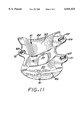
- FIG. 11 is a bottom perspective view of the grinding plate shown in FIG. 1.
- the grinding plate of the present invention includes, generally, a somewhat saddle shaped grind plate body 21 with an upwardly arched top side 23 for nesting in a cylindrically shaped concavity 25 formed in the sole 27 of a shoe.
- the bottom side of the saddle shaped grinding plate body 21 is formed with a downwardly facing arcuate trough 31 which is configured at its upper extent with a transverse bearing axis projecting generally horizontally in the medial portion (FIG.
- the trough 31 is formed by a pair of flanking cylindrical plate sectors defining medial and lateral concave bearing surfaces 33 and 35 spaced on opposite sides of a centrally located diagonal groove 41. Also included in the preferred embodiment is a parallelogramatic shaped hole 39 formed between the medial and lateral bearing surfaces 33 and 35 (FIG. 7).
- the grinding plate body 21 may take numerous different configurations and may attach to various different locations on the sole of a shoe.
- the sole 27 which is configured with a central cushion 41 surmounted on a heel 43 and forefoot outersole 45 each of which is formed with downwardly facing high friction tread as shown in FIG. 10.
- the midsole 27 is configured on its top side with a formed depression 51 and has through fastener fitting bores 55 and 57 arranged in an triangular shaped pattern for receipt of respective barrels 61 and 63 depending from a support shank generally designated 65 configured to complimentarily fit recess 51.
- the construction and performance of the shank 65 is set forth in greater detail in U.S. patent application Ser. No. 08/890,595 filed Jul. 9, 1997, and now U.S. Pat. No. 6,006,451, which application is incorporated herein by reference.
- the grinding plate body 21 is generally in the form of a sector of a cylinder and is configured to be complementally received in the cylindrically shaped concavity 25 in the midsole 27 (FIG. 10).
- the grinding plate body 21 is formed in top plan view with a generally longitudinally extending lateral edge 71 (FIG. 7) and a medial edge 73 which angles rearwardly and outwardly relative to the edge 71 to compliment the shape of the medial side of the midsole 27.
- the medial side 73 is formed with an upwardly raised medial flange 81 which angles rearwardly and inwardly to compliment the shape of the medial side of the shoe sole 27 and cooperate with the upper surface of the grind plate body 21 to provide enhanced support for the sole 27 during maneuvers by the wearer.
- the lateral side of the grind plate body 21 is formed with an upwardly raised longitudinally extending flange 83 which is complementally shaped to accommodate the lateral side of the shoe sole 27 in the arch area.
- the plate is formed along the opposite edges on the underside with the respective runners 82 and 84 having respective radii of curvature of which facilitate foot movement preferred by the athlete as the shoe is rolled from one side to the other during the grinding maneuver.
- the wearer's foot is typically manipulated through a certain variation of foot orientations resulting in the grinding plate being maneuvered through certain typical patterns which results in loading of the underside of such plate.
- the human anatomy dictates that when the knee is rolled outwardly in a lateral direction, the foot tends to pivot essentially about a center of curvature located at the lateral outside of the foot.
- the flexibility in the foot cooperates with the hip joint, knee and raised medial arch to allow greater flexibility and freedom in the inward rolling of the foot.
- the grind plate is approximately 10 centimeters wide at the front end and the side flange 83 angles rearwardly and inwardly in somewhat of a curved fashion to a 9 centimeter width at the rear end over a length of 9.5 centimeters.
- the body of the plate in the medial portion is 1.1 centimeters thick and the flanges 81 and 83 have an overall outside height along their major length of 1.3 centimeters from the extended trough bearing surface 31.
- I have curved the bearing surface upwardly and outwardly at the medial side at a radius of curvature of about 7 millimeters to form the medial runner 82 and curved the bearing surface upwardly and outwardly on the lateral side at a radius of curvature of 2.2 centimeters to form the lateral runner 84. It will be appreciated by those skilled in the art that such runners serve to accommodate different patterns of shoe manipulation and thus different foot manipulation on the underlying support rail surface for medial and lateral rolling of the athlete's knee.
- the groove 41 is about 2 centimeters wide throughout the majority of the length and expands centrally to about 2.5 centimeters in the area of the parallelogram shaped hole 39.
- the plate may be constructed of various different rigid low coefficient of friction materials such as metal, rubber, glass, ceramics and polyethylene composites. In the preferred embodiment, it is constructed of SUPERTUF® 801 nylon available from DuPont but other materials such as nylon 6 and PTEX® have been found to be acceptable. It will be noted that this groove 41 defining the unloaded area projects rearwardly and laterally at an angle of about 15° to the longitudinal center line of the plate and thus the longitudinal center line of the shoe sole 27.
- the groove 41 may be formed between the bearing surfaces 33 and 35 to thus remove a substantial amount of the plate mass without significantly detracting from the performance of the plate itself. Additionally, I have discovered in the central area of the plate, the groove may be extended up and to the body of the grinding plate so far as to totally remove the body material thus leaving a vertically through hole 39, again without detracting from the performance of the plate.
- I provide a textured trough surface which is roughened to provide better gripping of the under support surface to thereby facilitate control by the athlete as he or she maneuvers along the surface of the underlying rail.
- the shoe sole 27 be constructed in such a manner so that it can flex to accommodate the typical flexures associated with typical walking or running orientations of the human foot.
- I have configured my grind plate body 21 with on the rearward side an anchor ear 91 (FIG. 10) formed with a through bore 93 for receipt of a fastener screw 95 configured to be received upwardly through the bore 57 in the sole 27 to be screwably received into the barrel 63 of the shank 65.
- the grind plate body 21 is formed on its forward extremity with a pair of flanking fastener ears 101 and 103 which are configured with respective longitudinal grooves 107 and 109 aligned underneath the forward bores 55 and 57 in the sole 27 for receipt of a respective shoulder bolt fasteners 111 and 113 which screw into the respective forward barrels 61 of the shank 65. This then serves to securely anchor the back of the plate body 21 at the front of the heel 43 and to floatingly anchor the front extremity of the plate to the midsole 27 via the forward barrel 61 of the shank 65.
- the shoulder bolts 111 and 113 serve to provide for tightening of the fasteners while leaving some looseness for the respective ears 107 and 109 so that the shoe sole will be free to flex to a certain degree relative to the grind plate and thus relative to the rear anchor fastener 95 to allow for flexure of the sole 27 relative the grind plate to thus provide for a more natural gait during walking and running activities.
- the grind plate of the present invention may be fastened to a wearer's shoe or, for the saddle shaped plate shown in FIG. 1, may be nested upwardly into the concavity 25 of the midsole 27 shown in FIG. 10.
- Fastening to the shoe may be by straps, screws, bolts or the like.
- I have selected the threaded fasteners 95, 111 and 113 which are screwed intermedially into threaded barrels 61 and 63 of the shank 65.
- the fasteners in the form of screws or the like are screwed directly into a hard or soft soled shoe.
- the shoe is configured with a midsole 27 having the concavity 25 formed therein to be complementally fitted by the top side of the grind plate body 21. Indentations are formed for the respective ears 91, 101 and 103.
- the grind plate may be installed at the factory or may be sold separate from the shoe in the aftermarket. In any event, when the fasteners 95, 111 and 113 are inserted and screwed into position the grinding plate body 21 is drawn upwardly into the concavity 25 to such a degree that the lower most extent of the grinding plate is elevated above the horizontal plane through the bottom tread of the heel 43 and forefoot outersole 45.
- the 7 millimeters radius of curvature in the medial arch area serves to accommodate this maneuver in allowing the athlete to achieve the degree of performance sought.
- the kinetics of the inward and forward rolling of the knee allows the plate, and thus the shoe, to roll over onto runner 82 to itself rotate through a radius of 7 millimeters.
- the wearer rocks the shoe back to a erect position directly over the rail, curb or the like, one or more of the bearing surfaces 33 or 35 can engage such rail carrying so much weight as the wearer applies to that particular grind plate.
- the athlete's weight and momentum will be carried by the lateral generally horizontal, medial bearing surface along a width direction of about 7 centimeters thus affording good stability.
- the weight applied to the grind plate will be carried by the rounded surface of the lateral runner 84 allowing for extreme lateral knee bend. All this takes place in a relatively smooth manner due, in large extent, to the relatively large radius' of radii of curvature for the runner 84.
- the lower lateral foot arch, knee and hip joints cooperate with the 2.2 centimeter radius of curvature to thus allow the foot to rotate laterally outwardly about a center of curvature located almost in the vertical horizontal plane of the transverse center of the foot.
- This provides for efficient high performance for a young adult athlete wearing a shoe from about 7-10 in size.
- the ratios of dimensions could be changed for smaller or larger shoes sized to establish the proportionate contour for the same high performance.
- the grinding plate of the present invention provides a economical and convenient device for undertaking an athletic grinding maneuver utilizing a relatively light weight grinding plate which will possess all the performance characteristics associated with full bearing surface grinding plates but without the attendant weight.
Abstract
Description
Claims (34)
Priority Applications (1)
| Application Number | Priority Date | Filing Date | Title |
|---|---|---|---|
| US09/132,827 US6041525A (en) | 1996-07-23 | 1998-08-12 | Footwear grinding apparatus with flanking bearing surfaces |
Applications Claiming Priority (2)
| Application Number | Priority Date | Filing Date | Title |
|---|---|---|---|
| US2231896P | 1996-07-23 | 1996-07-23 | |
| US09/132,827 US6041525A (en) | 1996-07-23 | 1998-08-12 | Footwear grinding apparatus with flanking bearing surfaces |
Publications (1)
| Publication Number | Publication Date |
|---|---|
| US6041525A true US6041525A (en) | 2000-03-28 |
Family
ID=26695795
Family Applications (1)
| Application Number | Title | Priority Date | Filing Date |
|---|---|---|---|
| US09/132,827 Expired - Fee Related US6041525A (en) | 1996-07-23 | 1998-08-12 | Footwear grinding apparatus with flanking bearing surfaces |
Country Status (1)
| Country | Link |
|---|---|
| US (1) | US6041525A (en) |
Cited By (25)
| Publication number | Priority date | Publication date | Assignee | Title |
|---|---|---|---|---|
| US6195918B1 (en) * | 1996-07-23 | 2001-03-06 | Artemis Innovations Inc. | Grinding apparatus with flexible plate |
| US6247251B1 (en) | 2000-01-28 | 2001-06-19 | Artemis Innovations Inc. | Grind plate with removable inserts |
| US6357145B1 (en) | 1996-07-23 | 2002-03-19 | Artemis Innovations, Inc. | High performance lightweight grind shoe apparatus |
| US6406038B2 (en) | 1999-04-01 | 2002-06-18 | Heeling Sports Limited | Heeling apparatus and method |
| US6467198B1 (en) | 2000-12-13 | 2002-10-22 | Artemis Licensing Inc. | High flex grinding shoe |
| US6581943B2 (en) * | 2001-03-08 | 2003-06-24 | Sunshine Distribution, Inc. | H-block device for in-line skates |
| US20030127811A1 (en) * | 1999-04-01 | 2003-07-10 | Adams Roger R. | External wheeled heeling apparatus and method |
| US20030145493A1 (en) * | 2002-02-01 | 2003-08-07 | Adams Roger R. | Grind rail apparatus |
| US20030151215A1 (en) * | 2000-12-08 | 2003-08-14 | Aaron Stief | Sliding device |
| US6698769B2 (en) | 1999-04-01 | 2004-03-02 | Heeling Sports Limited | Multi-wheel heeling apparatus |
| US6863284B2 (en) | 2002-07-19 | 2005-03-08 | Andreas C. Wegener | In-line skate assembly with backslide plate |
| US20060027409A1 (en) * | 2004-08-04 | 2006-02-09 | Heeling Sports Limited | Motorized transportation apparatus and method |
| US7096605B1 (en) | 2003-10-08 | 2006-08-29 | Nike, Inc. | Article of footwear having an embedded plate structure |
| US7421808B2 (en) * | 2005-06-07 | 2008-09-09 | Converse Inc. | Simplified shoe construction with midsole having overmolded insert |
| US20080263900A1 (en) * | 2005-12-14 | 2008-10-30 | Djo France | Therapeutic Shoe |
| US20090026720A1 (en) * | 2007-07-23 | 2009-01-29 | Wegener Andreas C | Frame assembly for in-line skate |
| US7594666B2 (en) | 2006-06-13 | 2009-09-29 | Sunshine Distribution, Inc. | Skate assembly |
| US20110057400A1 (en) * | 2009-09-09 | 2011-03-10 | Ryan Daniel Wills | Wheeled platform apparatus and method for use with wheeled footwear |
| US20110061266A1 (en) * | 2009-09-15 | 2011-03-17 | Homeway Technology Co., Ltd. | Article of footwear that is waterproof, wear-resistant, and lightweight |
| US8303885B2 (en) | 2003-10-09 | 2012-11-06 | Nike, Inc. | Article of footwear with a stretchable upper and an articulated sole structure |
| US20120317835A1 (en) * | 2011-06-15 | 2012-12-20 | Skechers U.S.A., Inc. Ii | Shoe |
| US20140059896A1 (en) * | 2009-08-18 | 2014-03-06 | Adidas Ag | Outsole and sports shoe |
| US20160309840A1 (en) * | 2015-04-23 | 2016-10-27 | Action Sports Equipment, Inc. | Article of footwear with concave portion |
| US20190174873A1 (en) * | 2015-12-07 | 2019-06-13 | Nike, Inc. | Article Having Sole Assembly With Cleats |
| US10945485B2 (en) | 2012-08-03 | 2021-03-16 | Heeling Sports Limited | Heeling apparatus |
Citations (30)
| Publication number | Priority date | Publication date | Assignee | Title |
|---|---|---|---|---|
| US234030A (en) * | 1880-08-23 | 1880-11-02 | Shank support and protector for boots and shoes | |
| US579577A (en) * | 1896-06-04 | 1897-03-30 | Ladder-gripping attachment for boots or shoes | |
| US702476A (en) * | 1902-01-07 | 1902-06-17 | Joseph Hazzard Price | Shoe-protector. |
| US875560A (en) * | 1907-08-14 | 1907-12-31 | Elbert Vaughan | Shoe-protector. |
| US881079A (en) * | 1906-11-01 | 1908-03-03 | Friedrich Wilhelm Jolitz | Instep-protector. |
| US892152A (en) * | 1907-06-08 | 1908-06-30 | William Adalbert Harman | Foot-guard. |
| US1056091A (en) * | 1912-11-01 | 1913-03-18 | Theodore Dickson | Shoe-protector. |
| US1189329A (en) * | 1916-01-29 | 1916-07-04 | Daniel E Winagle | Shoe-protector. |
| US1428232A (en) * | 1920-04-05 | 1922-09-05 | Holmen Jacob | Shoe guard |
| US1592692A (en) * | 1923-11-06 | 1926-07-13 | Fahrlender Grayce | Shoe protector |
| US1636909A (en) * | 1927-03-12 | 1927-07-26 | Haney William John | Metal dancing-shoe sole |
| US1637897A (en) * | 1924-03-24 | 1927-08-02 | Cordo Hyde Co | Shoe and process of making the same |
| GB362752A (en) * | 1931-02-02 | 1931-12-10 | Lionel Andrews | Improvements relating to footwear |
| US1984989A (en) * | 1934-12-18 | Pedal attachment for dancing | ||
| US2060391A (en) * | 1933-10-19 | 1936-11-10 | Castagnola Oliver | Built-in arch support |
| US2476806A (en) * | 1945-12-29 | 1949-07-19 | Jr Francis L Brandt | Heel brace |
| US2484935A (en) * | 1947-09-05 | 1949-10-18 | Thor Melanchton Peterson | Sole protector |
| US3058240A (en) * | 1959-10-09 | 1962-10-16 | Charline R Osgood | Basic shoe unit |
| US3486250A (en) * | 1968-03-05 | 1969-12-30 | Russell W Purtle | Shoe attachment |
| US4691453A (en) * | 1986-09-08 | 1987-09-08 | Salustiano Tifre | Space skating shoe |
| US5249376A (en) * | 1992-11-16 | 1993-10-05 | Michael Capria | Shoe heel with rollers |
| US5319866A (en) * | 1991-08-21 | 1994-06-14 | Reebok International Ltd. | Composite arch member |
| US5388350A (en) * | 1992-12-31 | 1995-02-14 | Parker, Jr.; Bill H. | Roller shoe construction |
| US5398970A (en) * | 1993-07-28 | 1995-03-21 | Tucky; Edward W. | Shoes for walking and roller skating |
| US5410821A (en) * | 1992-01-21 | 1995-05-02 | Hilgendorf; Eric | Shoe with interchangable soles |
| US5425186A (en) * | 1994-04-15 | 1995-06-20 | Hoyt; David | Overshoe with an accordian type sole |
| WO1997011652A1 (en) * | 1995-09-25 | 1997-04-03 | Nordiska Dental Ab | Burr |
| US5632104A (en) * | 1994-10-04 | 1997-05-27 | Zohar; Itzchak | Shoes for reducing stress in feet |
| US5638614A (en) * | 1995-12-18 | 1997-06-17 | Hardy; Chris | Shoe protector and floor covering aid |
| US5716723A (en) * | 1996-03-07 | 1998-02-10 | Van Cleef; James Gresham | Glow in the dark shoe sole |
-
1998
- 1998-08-12 US US09/132,827 patent/US6041525A/en not_active Expired - Fee Related
Patent Citations (30)
| Publication number | Priority date | Publication date | Assignee | Title |
|---|---|---|---|---|
| US1984989A (en) * | 1934-12-18 | Pedal attachment for dancing | ||
| US234030A (en) * | 1880-08-23 | 1880-11-02 | Shank support and protector for boots and shoes | |
| US579577A (en) * | 1896-06-04 | 1897-03-30 | Ladder-gripping attachment for boots or shoes | |
| US702476A (en) * | 1902-01-07 | 1902-06-17 | Joseph Hazzard Price | Shoe-protector. |
| US881079A (en) * | 1906-11-01 | 1908-03-03 | Friedrich Wilhelm Jolitz | Instep-protector. |
| US892152A (en) * | 1907-06-08 | 1908-06-30 | William Adalbert Harman | Foot-guard. |
| US875560A (en) * | 1907-08-14 | 1907-12-31 | Elbert Vaughan | Shoe-protector. |
| US1056091A (en) * | 1912-11-01 | 1913-03-18 | Theodore Dickson | Shoe-protector. |
| US1189329A (en) * | 1916-01-29 | 1916-07-04 | Daniel E Winagle | Shoe-protector. |
| US1428232A (en) * | 1920-04-05 | 1922-09-05 | Holmen Jacob | Shoe guard |
| US1592692A (en) * | 1923-11-06 | 1926-07-13 | Fahrlender Grayce | Shoe protector |
| US1637897A (en) * | 1924-03-24 | 1927-08-02 | Cordo Hyde Co | Shoe and process of making the same |
| US1636909A (en) * | 1927-03-12 | 1927-07-26 | Haney William John | Metal dancing-shoe sole |
| GB362752A (en) * | 1931-02-02 | 1931-12-10 | Lionel Andrews | Improvements relating to footwear |
| US2060391A (en) * | 1933-10-19 | 1936-11-10 | Castagnola Oliver | Built-in arch support |
| US2476806A (en) * | 1945-12-29 | 1949-07-19 | Jr Francis L Brandt | Heel brace |
| US2484935A (en) * | 1947-09-05 | 1949-10-18 | Thor Melanchton Peterson | Sole protector |
| US3058240A (en) * | 1959-10-09 | 1962-10-16 | Charline R Osgood | Basic shoe unit |
| US3486250A (en) * | 1968-03-05 | 1969-12-30 | Russell W Purtle | Shoe attachment |
| US4691453A (en) * | 1986-09-08 | 1987-09-08 | Salustiano Tifre | Space skating shoe |
| US5319866A (en) * | 1991-08-21 | 1994-06-14 | Reebok International Ltd. | Composite arch member |
| US5410821A (en) * | 1992-01-21 | 1995-05-02 | Hilgendorf; Eric | Shoe with interchangable soles |
| US5249376A (en) * | 1992-11-16 | 1993-10-05 | Michael Capria | Shoe heel with rollers |
| US5388350A (en) * | 1992-12-31 | 1995-02-14 | Parker, Jr.; Bill H. | Roller shoe construction |
| US5398970A (en) * | 1993-07-28 | 1995-03-21 | Tucky; Edward W. | Shoes for walking and roller skating |
| US5425186A (en) * | 1994-04-15 | 1995-06-20 | Hoyt; David | Overshoe with an accordian type sole |
| US5632104A (en) * | 1994-10-04 | 1997-05-27 | Zohar; Itzchak | Shoes for reducing stress in feet |
| WO1997011652A1 (en) * | 1995-09-25 | 1997-04-03 | Nordiska Dental Ab | Burr |
| US5638614A (en) * | 1995-12-18 | 1997-06-17 | Hardy; Chris | Shoe protector and floor covering aid |
| US5716723A (en) * | 1996-03-07 | 1998-02-10 | Van Cleef; James Gresham | Glow in the dark shoe sole |
Cited By (47)
| Publication number | Priority date | Publication date | Assignee | Title |
|---|---|---|---|---|
| US6357145B1 (en) | 1996-07-23 | 2002-03-19 | Artemis Innovations, Inc. | High performance lightweight grind shoe apparatus |
| US6195918B1 (en) * | 1996-07-23 | 2001-03-06 | Artemis Innovations Inc. | Grinding apparatus with flexible plate |
| US9242169B2 (en) | 1999-04-01 | 2016-01-26 | Heeling Sports Limited | Heeling apparatus |
| US6739602B2 (en) | 1999-04-01 | 2004-05-25 | Heeling Sports Limited | Heeling apparatus and method |
| US6450509B2 (en) | 1999-04-01 | 2002-09-17 | Heeling Sports Limited | Heeling apparatus and method |
| USD866133S1 (en) | 1999-04-01 | 2019-11-12 | Heeling Sports Limited | Shoe with wheel |
| US20070164519A1 (en) * | 1999-04-01 | 2007-07-19 | Heeling Sports Limited | Heeling apparatus and method |
| US20030127811A1 (en) * | 1999-04-01 | 2003-07-10 | Adams Roger R. | External wheeled heeling apparatus and method |
| US8480095B2 (en) | 1999-04-01 | 2013-07-09 | Heeling Sports Limited | Heeling apparatus wheel assembly |
| US20060232027A1 (en) * | 1999-04-01 | 2006-10-19 | Adams Roger R | External wheeled heeling apparatus and method |
| US6698769B2 (en) | 1999-04-01 | 2004-03-02 | Heeling Sports Limited | Multi-wheel heeling apparatus |
| US6406038B2 (en) | 1999-04-01 | 2002-06-18 | Heeling Sports Limited | Heeling apparatus and method |
| US6746026B2 (en) | 1999-04-01 | 2004-06-08 | Heeling Sports Limited | Heeling apparatus and method |
| US9776067B2 (en) | 1999-04-01 | 2017-10-03 | Heeling Sports Limited | Heeling apparatus |
| US20040222601A1 (en) * | 1999-04-01 | 2004-11-11 | Adams Roger R. | Heeling apparatus and method |
| US20060108752A1 (en) * | 1999-04-01 | 2006-05-25 | Heeling Sports Limited | Heeling apparatus and method |
| US20100117314A1 (en) * | 1999-04-01 | 2010-05-13 | Adams Roger R | Heeling apparatus wheel assembly |
| US6247251B1 (en) | 2000-01-28 | 2001-06-19 | Artemis Innovations Inc. | Grind plate with removable inserts |
| US6773021B2 (en) | 2000-12-08 | 2004-08-10 | The Burton Corporation | Sliding device |
| US20030151215A1 (en) * | 2000-12-08 | 2003-08-14 | Aaron Stief | Sliding device |
| US6467198B1 (en) | 2000-12-13 | 2002-10-22 | Artemis Licensing Inc. | High flex grinding shoe |
| US6581943B2 (en) * | 2001-03-08 | 2003-06-24 | Sunshine Distribution, Inc. | H-block device for in-line skates |
| US20030145493A1 (en) * | 2002-02-01 | 2003-08-07 | Adams Roger R. | Grind rail apparatus |
| US6863284B2 (en) | 2002-07-19 | 2005-03-08 | Andreas C. Wegener | In-line skate assembly with backslide plate |
| US7096605B1 (en) | 2003-10-08 | 2006-08-29 | Nike, Inc. | Article of footwear having an embedded plate structure |
| US8959802B2 (en) | 2003-10-09 | 2015-02-24 | Nike, Inc. | Article of footwear with a stretchable upper and an articulated sole structure |
| US8303885B2 (en) | 2003-10-09 | 2012-11-06 | Nike, Inc. | Article of footwear with a stretchable upper and an articulated sole structure |
| US20100051372A1 (en) * | 2004-08-04 | 2010-03-04 | Adams Roger R | Motorized transportation apparatus and method |
| US20060027409A1 (en) * | 2004-08-04 | 2006-02-09 | Heeling Sports Limited | Motorized transportation apparatus and method |
| US20080301887A1 (en) * | 2005-06-07 | 2008-12-11 | Converse Inc. | Simplified shoe construction with midsole having overmolded insert |
| US7421808B2 (en) * | 2005-06-07 | 2008-09-09 | Converse Inc. | Simplified shoe construction with midsole having overmolded insert |
| US7883658B2 (en) | 2005-06-07 | 2011-02-08 | Converse Inc. | Simplified shoe construction with midsole having overmolded insert |
| US20080263900A1 (en) * | 2005-12-14 | 2008-10-30 | Djo France | Therapeutic Shoe |
| US7594666B2 (en) | 2006-06-13 | 2009-09-29 | Sunshine Distribution, Inc. | Skate assembly |
| US7931283B2 (en) | 2007-07-23 | 2011-04-26 | Sunshine Distribution, Inc. | Frame assembly for in-line skate |
| US20090026720A1 (en) * | 2007-07-23 | 2009-01-29 | Wegener Andreas C | Frame assembly for in-line skate |
| US20140059896A1 (en) * | 2009-08-18 | 2014-03-06 | Adidas Ag | Outsole and sports shoe |
| US9326562B2 (en) * | 2009-08-18 | 2016-05-03 | Adidas Ag | Outsole and sports shoe |
| US20110057400A1 (en) * | 2009-09-09 | 2011-03-10 | Ryan Daniel Wills | Wheeled platform apparatus and method for use with wheeled footwear |
| US20110061266A1 (en) * | 2009-09-15 | 2011-03-17 | Homeway Technology Co., Ltd. | Article of footwear that is waterproof, wear-resistant, and lightweight |
| US20120317835A1 (en) * | 2011-06-15 | 2012-12-20 | Skechers U.S.A., Inc. Ii | Shoe |
| US10945485B2 (en) | 2012-08-03 | 2021-03-16 | Heeling Sports Limited | Heeling apparatus |
| US9596906B2 (en) * | 2015-04-23 | 2017-03-21 | Action Sports Equipment, Inc. | Article of footwear with concave portion |
| US20170105472A1 (en) * | 2015-04-23 | 2017-04-20 | Action Sports Equipment, Inc. | Article of footwear with concave portion |
| US20160309840A1 (en) * | 2015-04-23 | 2016-10-27 | Action Sports Equipment, Inc. | Article of footwear with concave portion |
| US20190174873A1 (en) * | 2015-12-07 | 2019-06-13 | Nike, Inc. | Article Having Sole Assembly With Cleats |
| US10897961B2 (en) * | 2015-12-07 | 2021-01-26 | Nike, Inc. | Article having sole assembly with cleats |
Similar Documents
| Publication | Publication Date | Title |
|---|---|---|
| US6041525A (en) | Footwear grinding apparatus with flanking bearing surfaces | |
| US6006451A (en) | Footwear apparatus with grinding plate and method of making same | |
| US6115946A (en) | Method for making footwear grinding apparatus | |
| US6006450A (en) | Wear resistant grind shoe apparatus | |
| US6195920B1 (en) | Grinding footwear apparatus with storage compartment | |
| US7464944B2 (en) | Wheeled skate | |
| US6195918B1 (en) | Grinding apparatus with flexible plate | |
| US5794362A (en) | Size adjustable athletic boot | |
| US6467198B1 (en) | High flex grinding shoe | |
| US5848796A (en) | In-line roller skate | |
| US5331752A (en) | Skate with detachable shoe | |
| US20040025374A1 (en) | Sole/support assembly for a boot and a boot incorporating such sole/support assembly | |
| US20030155725A1 (en) | Shoes for walking and rolling | |
| US20070296164A1 (en) | Personal Locomotion | |
| JPH01308501A (en) | Sole shape for shoes | |
| CA2512252A1 (en) | Flexing base skate | |
| US8960711B2 (en) | Ski boot | |
| US5802741A (en) | Snowboard boot | |
| US20030141680A1 (en) | Roller shoe | |
| US6151806A (en) | Grinding footwear apparatus including plate with braking surfaces | |
| US5947486A (en) | Biodynamic roller skate | |
| US7040633B2 (en) | Rolling or gliding sports equipment | |
| US5979939A (en) | Accessory for in-line skates | |
| WO1998033565A1 (en) | In-line roller skate with frame interface | |
| WO1997009099A1 (en) | In-line skate with liner-attached brake actuator |
Legal Events
| Date | Code | Title | Description |
|---|---|---|---|
| AS | Assignment |
Owner name: ARTEMIS INNOVATIONS, INC., CALIFORNIA Free format text: ASSIGNMENT OF ASSIGNORS INTEREST;ASSIGNOR:KELLEY, BENJAMIN B.;REEL/FRAME:009397/0446 Effective date: 19980811 |
|
| AS | Assignment |
Owner name: IMPERIAL BANK, CALIFORNIA Free format text: SECURITY AGREEMENT;ASSIGNOR:ARTEMIS INNOVATIONS, INC.;REEL/FRAME:010272/0216 Effective date: 19990525 |
|
| AS | Assignment |
Owner name: ARTEMIS INNOVATIONS, INC., CALIFORNIA Free format text: TERMINATION OF SECURITY INTEREST;ASSIGNOR:IMPERIAL BANK;REEL/FRAME:011390/0651 Effective date: 20001110 |
|
| AS | Assignment |
Owner name: ARTEMIS LICENSING, CALIFORNIA Free format text: ASSIGNMENT OF ASSIGNORS INTEREST;ASSIGNOR:ARTEMIS INNOVATIONS INC.;REEL/FRAME:012906/0591 Effective date: 20001209 |
|
| AS | Assignment |
Owner name: CURTIS HOLDINGS, LLC, MINNESOTA Free format text: SECURITY AGREEMENT;ASSIGNOR:ARTEMIS LICENSING;REEL/FRAME:013288/0422 Effective date: 20020530 Owner name: CURTIS HOLDINGS, LLC, MINNESOTA Free format text: ASSIGNMENT OF ASSIGNORS INTEREST;ASSIGNOR:ARTEMIS LICENSING;REEL/FRAME:013295/0205 Effective date: 20020530 |
|
| REMI | Maintenance fee reminder mailed | ||
| AS | Assignment |
Owner name: CURTIS HOLDINS, LLC, MINNESOTA Free format text: SURRENDER OF SECURITY INTEREST;ASSIGNOR:LICENSING, ARTEMIS;REEL/FRAME:014709/0439 Effective date: 20030930 |
|
| FPAY | Fee payment |
Year of fee payment: 4 |
|
| SULP | Surcharge for late payment | ||
| AS | Assignment |
Owner name: HEELING SPORTS LIMITED, TEXAS Free format text: ASSIGNMENT OF ASSIGNORS INTEREST;ASSIGNOR:CURTIS HOLDINGS, LLC;REEL/FRAME:016996/0092 Effective date: 20060105 |
|
| REMI | Maintenance fee reminder mailed | ||
| LAPS | Lapse for failure to pay maintenance fees | ||
| STCH | Information on status: patent discontinuation |
Free format text: PATENT EXPIRED DUE TO NONPAYMENT OF MAINTENANCE FEES UNDER 37 CFR 1.362 |
|
| FP | Lapsed due to failure to pay maintenance fee |
Effective date: 20080328 |
|
| AS | Assignment |
Owner name: BANK OF AMERICA, N.A., AS COLLATERAL AGENT, MASSACHUSETTS Free format text: SECURITY AGREEMENT;ASSIGNOR:HEELING SPORTS LIMITED;REEL/FRAME:030111/0501 Effective date: 20130328 Owner name: PATHLIGHT CAPITAL, LLC, AS COLLATERAL AGENT, MASSACHUSETTS Free format text: SECURITY AGREEMENT;ASSIGNOR:HEELING SPORTS LIMITED;REEL/FRAME:030111/0769 Effective date: 20130328 Owner name: PATHLIGHT CAPITAL, LLC, AS COLLATERAL AGENT, MASSA Free format text: SECURITY AGREEMENT;ASSIGNOR:HEELING SPORTS LIMITED;REEL/FRAME:030111/0769 Effective date: 20130328 Owner name: BANK OF AMERICA, N.A., AS COLLATERAL AGENT, MASSAC Free format text: SECURITY AGREEMENT;ASSIGNOR:HEELING SPORTS LIMITED;REEL/FRAME:030111/0501 Effective date: 20130328 |
|
| AS | Assignment |
Owner name: SBG REVO HOLDINGS, LLC, NEW YORK Free format text: TERMINATION AND RELEASE OF GRANT OF SECURITY INTEREST IN PATENTS;ASSIGNOR:PATHLIGHT CAPITAL, LLC, AS COLLATERAL AGENT;REEL/FRAME:033577/0979 Effective date: 20140815 Owner name: HEELING SPORTS LIMITED, TEXAS Free format text: TERMINATION AND RELEASE OF GRANT OF SECURITY INTEREST IN PATENTS;ASSIGNOR:PATHLIGHT CAPITAL, LLC, AS COLLATERAL AGENT;REEL/FRAME:033577/0979 Effective date: 20140815 |