US6033109A - Device for calibrating thermistor voltages to temperature values by using rough and fine lookup tables - Google Patents
Device for calibrating thermistor voltages to temperature values by using rough and fine lookup tables Download PDFInfo
- Publication number
- US6033109A US6033109A US09/080,302 US8030298A US6033109A US 6033109 A US6033109 A US 6033109A US 8030298 A US8030298 A US 8030298A US 6033109 A US6033109 A US 6033109A
- Authority
- US
- United States
- Prior art keywords
- temperature
- voltage
- values
- increment
- thermistor
- Prior art date
- Legal status (The legal status is an assumption and is not a legal conclusion. Google has not performed a legal analysis and makes no representation as to the accuracy of the status listed.)
- Expired - Lifetime
Links
Images
Classifications
-
- G—PHYSICS
- G01—MEASURING; TESTING
- G01K—MEASURING TEMPERATURE; MEASURING QUANTITY OF HEAT; THERMALLY-SENSITIVE ELEMENTS NOT OTHERWISE PROVIDED FOR
- G01K1/00—Details of thermometers not specially adapted for particular types of thermometer
- G01K1/02—Means for indicating or recording specially adapted for thermometers
- G01K1/028—Means for indicating or recording specially adapted for thermometers arrangements for numerical indication
-
- G—PHYSICS
- G01—MEASURING; TESTING
- G01K—MEASURING TEMPERATURE; MEASURING QUANTITY OF HEAT; THERMALLY-SENSITIVE ELEMENTS NOT OTHERWISE PROVIDED FOR
- G01K7/00—Measuring temperature based on the use of electric or magnetic elements directly sensitive to heat ; Power supply therefor, e.g. using thermoelectric elements
- G01K7/16—Measuring temperature based on the use of electric or magnetic elements directly sensitive to heat ; Power supply therefor, e.g. using thermoelectric elements using resistive elements
- G01K7/22—Measuring temperature based on the use of electric or magnetic elements directly sensitive to heat ; Power supply therefor, e.g. using thermoelectric elements using resistive elements the element being a non-linear resistance, e.g. thermistor
- G01K7/24—Measuring temperature based on the use of electric or magnetic elements directly sensitive to heat ; Power supply therefor, e.g. using thermoelectric elements using resistive elements the element being a non-linear resistance, e.g. thermistor in a specially-adapted circuit, e.g. bridge circuit
- G01K7/25—Measuring temperature based on the use of electric or magnetic elements directly sensitive to heat ; Power supply therefor, e.g. using thermoelectric elements using resistive elements the element being a non-linear resistance, e.g. thermistor in a specially-adapted circuit, e.g. bridge circuit for modifying the output characteristic, e.g. linearising
Definitions
- the present invention relates in general to a voltage-to-temperature value conversion device, more particularly, to a device for converting voltages to temperature values by using a thermistor.
- thermistors are applied to measure the ambient temperature of electronic apparatus, such as the temperature of the motherboard, CPU, and charging battery etc.
- the temperature specifications of thermistors are within the range between about -40° C. and +120° C., and the resistance of a thermistor decreases as the temperature increases.
- the general applications of electronic devices, such as the temperature-control of a refrigerator etc. also use thermistors to measure and control temperature.
- the thermistor is disposed in electronic apparatus where temperature is to be measured. As the temperature varies, the voltage drop across the thermistor changes to a corresponding value. After taking the voltage, the practical temperature can be obtained by referencing the voltage(resistance)-temperature characteristic curve of the thermistor.
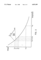
- the voltage-temperature characteristic curve of a thermistor is a logarithm-like curve, as depicted in FIG. 2. To fit the curve, a lot of voltage value and temperature value sampling pairs are required.
- the voltage-temperature characteristic curve of the thermistor is transformed into a voltage-temperature cross-reference table such that the voltage measured from the thermistor can be easily transformed into a corresponding temperature.
- the conventional voltage-temperature cross-reference table is implemented in a one-to-one manner by storing every one of the voltage values and every corresponding temperature value sampled from the voltage-temperature curve into a memory device, such as RAM and ROM. Consequently, the amount of memory required and the fabrication cost are increased.
- an object of the present invention is to provide a device for converting voltage to temperature by using a thermistor.
- the present invention does not use the conventional voltage-temperature characteristic curve to carry out voltage-temperature conversion, thereby reducing the required capacity of RAM or ROM and the cost.
- the present invention achieves the above-indicated objects by providing a device for converting voltages to temperatures comprising the following units.
- a thermistor and a division resistor are connected in series, wherein one terminal of the thermistor is grounded, and one terminal of the division resistor is connected to a voltage source, and the thermistor is disposed at the place where the temperature is to be measured, and the voltage across the thermistor varies with respect to changes of temperature.
- An analog-to-digital converter receives the voltage of the thermistor and transforms it into a digital output.
- a first multiplexer decodes the higher bit portion of the digital output, thereby selecting a corresponding temperature from a voltage-temperature cross-reference table as a rough temperature.
- a second multiplexer decodes the higher bit portion of the digital output, thereby selecting a corresponding temperature increment from a temperature-increment table as a temperature step.
- a multiplier multiplies the lower bit portion of the digit output by the temperature step to obtain a fine temperature.
- An adder adds the fine temperature to the rough temperature to output a practical temperature.
- the voltage-temperature cross-reference table is set and stored in the first storage device, and the temperature-increment table is set and stored in the second storage device.
- the voltage-temperature cross-reference table and the temperature-increment table are used for constructing a voltage-temperature characteristic curve by means of interpolation such that the voltage drop across the thermistor can be transformed into proper temperature in reference of the constructed voltage-temperature characteristic curve.
- the required memory for storing the voltage-temperature cross-reference table and the temperature-increment table is smaller than that required to store the conventional voltage-temperature cross-reference table.
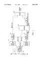
- FIG. 1 schematically shows the circuit diagram of the voltage-temperature converting device according to the present invention.
- FIG. 2 shows the voltage(resistance)-temperature characteristic curve of a thermistor.
- FIG. 1 The device for converting voltage to temperature according to the present invention is schematically shown in FIG. 1.
- a division resistor R1 and a thermistor Rt are connected in series, and disposed between a reference voltage source Vref and ground.
- the thermistor is disposed in the place where the temperature is to be measured.
- the voltage Vt of the thermistor Rt changes correspondingly.
- the voltage Vt outputs to an analog-to-digital converter 11.
- a 8-bit analog-to-digital converter is adopted, wherein the 8-bit digital output value of the converter 11 is represented as AD ⁇ 7:0>, and AD ⁇ 7:4> means the higher bit portion of the digital output AD ⁇ 7:0>, while AD ⁇ 3:0> means the lower bit portion of the digital output AD ⁇ 7:0>.
- the values (0h, 1h, 2h ⁇ Fh) of the higher bit portion AD ⁇ 7:4> of the digital output AD ⁇ 7:0> correspond to the node voltages V l5 , V 14 , V 13 ⁇ V 0 respectively, and therefore the temperatures T 0 , T 1 ⁇ T 15 serve as rough temperatures converted from the higher bit portion AD ⁇ 7:4>.
- the 8-bit temperature values T 0 , T 1 ⁇ T 15 are stored in a first storage device 12, thereby forming a voltage-temperature cross-reference table.
- the T 0 -T 1 temperature segment is further divided into 16 equal partitions, and the value of every partition do serves as the temperature increment of T 0 -T 1 temperature segment.
- each of the other temperature segments, T 1 -T 2 , T 2 -T 3 ⁇ T 14 -T l5 is further divided into 16 equal partitions respectively, and the temperature increments d 1 , d 2 ⁇ d 15 of the other temperature segments are obtained.
- the 8-bit temperature increments d 0 , d 1 , d 2 ⁇ d 15 are stored in a second storage device 13, thereby forming a temperature-increment table.
- the temperature increments d 15 , d 14 , d 13 ⁇ d 0 correspond to the values (0h, 1h, 2h ⁇ Fh) of the higher bit portion AD ⁇ 7:4> of the digital output.
- the higher bit portion AD ⁇ 7:4> is decoded by a first multiplexer 14, and a rough temperature corresponding to the higher bit portion AD ⁇ 7:4> is selected form the voltage-temperature cross-reference table.
- the higher bit portion AD ⁇ 7:4> is decoded by a second multiplexer 15, and a temperature increment corresponding to the higher bit portion AD ⁇ 7:4> is selected from the temperature-increment table and serves as a temperature step.
- the outputs of the first multiplexer 14 and the second multiplexer 15 are MRGH ⁇ 7:0> (8-bit) and MINC ⁇ 4:0> (5-bit) respectively.
- the decoding result (rough temperature) MRGH ⁇ 7:0> is T 0
- the corresponding temperature increment (temperature step) MINC ⁇ 4:0> is d 0 .
- the multiplier 16 multiplies the lower bit portion AD ⁇ 3:0> of the analog-to-digital output by the temperature step MINC ⁇ 4:0>, thereby obtaining a fine temperature MTVAL ⁇ 8:0> (9-bit). For example, if the AD ⁇ 3:0> is 2h, then the fine temperature is MTVAL ⁇ 8:0> 2d 0 . To meet the requirement of precision, only the higher bit portion of the fine temperature MTVAL ⁇ 8:0> needs to be taken into account, and therefore a bit selector 17 is used to choose the higher bit portion of the fine temperature MTVAL ⁇ 8:0>, according to the specification of the precision. In this case, the higher 5 bits of the fine temperature MTVAL ⁇ 8:0> are selected, and therefore the bit selector 17 outputs MTVAL ⁇ 8:4>.
- an adder 18 adds the truncated fine temperature MTVAL ⁇ 8:4> to the rough temperature MRGH ⁇ 7:0> and generates a practical temperature TRUEVAL ⁇ 7:0>.
- the practical temperature TRUEVAL ⁇ 7:0> equals T 0 +2d 0 .
- the device utilizes a voltage-temperature cross-reference table and a temperature-increment table to reconstruct a piecewise voltage-temperature characteristic curve of the thermistor, thereby carrying out the voltage to temperature transformation.
- 16 rough temperature values and 16 temperature increment values are stored respectively to form the voltage-temperature cross-reference table and the temperature-increment table, and a conversion precision of 256 levels can be achieved, wherein only 32 values are stored.
- the conventional voltage-temperature cross-reference table needs to store 256 temperature values to achieve the same conversion precision (256 levels).
- the memory required to store the values by the conventional conversion device is eight times of that required by the device in accordance with the present invention. Consequently, it is quite obvious that the present invention can reduce the amount of memory required to store the data of the voltage-temperature characteristic curve of a thermistor, and is very simple to implement, thereby reducing the fabrication cost.
Abstract
A device appropriate for converting voltages to temperature values by using a thermistor is disclosed. The device according to the present invention utilizes a voltage-temperature cross-reference table and a temperature-increment table to carry out the conversion instead of using the conventional one-to-one voltage-temperature table, thereby reducing the required capacity of RAM and ROM and the fabrication cost. The thermistor is disposed at the place where the temperature is to be measured, and the voltage across the thermistor varies with respect to changes of temperature. An analog-to-digital converter receives the voltage of the thermistor and transforms it into digital output. A first multiplexer decodes the higher bit portion of the digital output thereby selecting a corresponding temperature from a voltage-temperature cross-reference table as a rough temperature. A second multiplexer decodes the higher bit portion of the digital output thereby selecting a corresponding temperature increment from a temperature-increment table as a temperature step. A multiplier multiplies the lower bit portion of the digit output by the temperature step to obtain a fine temperature. An adder adds the fine temperature to the rough temperature to output a practical temperature value.
Description
1. Field of the Invention
The present invention relates in general to a voltage-to-temperature value conversion device, more particularly, to a device for converting voltages to temperature values by using a thermistor.
2. Description of the Related Art
In general, thermistors are applied to measure the ambient temperature of electronic apparatus, such as the temperature of the motherboard, CPU, and charging battery etc. In general, the temperature specifications of thermistors are within the range between about -40° C. and +120° C., and the resistance of a thermistor decreases as the temperature increases. The general applications of electronic devices, such as the temperature-control of a refrigerator etc., also use thermistors to measure and control temperature. The thermistor is disposed in electronic apparatus where temperature is to be measured. As the temperature varies, the voltage drop across the thermistor changes to a corresponding value. After taking the voltage, the practical temperature can be obtained by referencing the voltage(resistance)-temperature characteristic curve of the thermistor.
The voltage-temperature characteristic curve of a thermistor is a logarithm-like curve, as depicted in FIG. 2. To fit the curve, a lot of voltage value and temperature value sampling pairs are required. The voltage-temperature characteristic curve of the thermistor is transformed into a voltage-temperature cross-reference table such that the voltage measured from the thermistor can be easily transformed into a corresponding temperature. However, the conventional voltage-temperature cross-reference table is implemented in a one-to-one manner by storing every one of the voltage values and every corresponding temperature value sampled from the voltage-temperature curve into a memory device, such as RAM and ROM. Consequently, the amount of memory required and the fabrication cost are increased.
Therefore, an object of the present invention is to provide a device for converting voltage to temperature by using a thermistor. The present invention does not use the conventional voltage-temperature characteristic curve to carry out voltage-temperature conversion, thereby reducing the required capacity of RAM or ROM and the cost.
The present invention achieves the above-indicated objects by providing a device for converting voltages to temperatures comprising the following units.
A thermistor and a division resistor are connected in series, wherein one terminal of the thermistor is grounded, and one terminal of the division resistor is connected to a voltage source, and the thermistor is disposed at the place where the temperature is to be measured, and the voltage across the thermistor varies with respect to changes of temperature.
An analog-to-digital converter receives the voltage of the thermistor and transforms it into a digital output.
A first multiplexer decodes the higher bit portion of the digital output, thereby selecting a corresponding temperature from a voltage-temperature cross-reference table as a rough temperature.
A second multiplexer decodes the higher bit portion of the digital output, thereby selecting a corresponding temperature increment from a temperature-increment table as a temperature step. A multiplier multiplies the lower bit portion of the digit output by the temperature step to obtain a fine temperature. An adder adds the fine temperature to the rough temperature to output a practical temperature.
The voltage-temperature cross-reference table is set and stored in the first storage device, and the temperature-increment table is set and stored in the second storage device.
In the present invention, the voltage-temperature cross-reference table and the temperature-increment table are used for constructing a voltage-temperature characteristic curve by means of interpolation such that the voltage drop across the thermistor can be transformed into proper temperature in reference of the constructed voltage-temperature characteristic curve. Moreover, the required memory for storing the voltage-temperature cross-reference table and the temperature-increment table is smaller than that required to store the conventional voltage-temperature cross-reference table.
The following detailed description, given by way of example and not intended to limit the invention solely to the embodiments described herein, will best be understood in conjunction with the accompanying drawings, in which:
FIG. 1 schematically shows the circuit diagram of the voltage-temperature converting device according to the present invention; and
FIG. 2 shows the voltage(resistance)-temperature characteristic curve of a thermistor.
The device for converting voltage to temperature according to the present invention is schematically shown in FIG. 1. In FIG. 1, a division resistor R1 and a thermistor Rt are connected in series, and disposed between a reference voltage source Vref and ground. In general, the thermistor is disposed in the place where the temperature is to be measured. As the temperature varies, the voltage Vt of the thermistor Rt changes correspondingly. The voltage Vt outputs to an analog-to-digital converter 11. In this embodiment, a 8-bit analog-to-digital converter is adopted, wherein the 8-bit digital output value of the converter 11 is represented as AD<7:0>, and AD<7:4> means the higher bit portion of the digital output AD<7:0>, while AD<3:0> means the lower bit portion of the digital output AD<7:0>.
The way to establish the voltage-temperature cross-reference table and the temperature-increment table in accordance with the present invention is described as follows in accompaniment with FIG. 2. In the voltage-temperature characteristic curve of the thermistor Rt, a plurality of node voltages V0, V1 ˜V15 are selected to divide the voltage coordinate into several segments, and the node voltages V0, V1 ˜V15 have their corresponding temperature values T0, T1 ˜T15 respectively at the temperature coordinates. The values (0h, 1h, 2h˜Fh) of the higher bit portion AD<7:4> of the digital output AD<7:0>, correspond to the node voltages Vl5, V14, V13 ˜V0 respectively, and therefore the temperatures T0, T1 ˜T15 serve as rough temperatures converted from the higher bit portion AD<7:4>. The 8-bit temperature values T0, T1 ˜T15 are stored in a first storage device 12, thereby forming a voltage-temperature cross-reference table.
Referring to FIG. 2, the T0 -T1 temperature segment is further divided into 16 equal partitions, and the value of every partition do serves as the temperature increment of T0 -T1 temperature segment. Similarly, each of the other temperature segments, T1 -T2, T2 -T3 ˜T14 -Tl5, is further divided into 16 equal partitions respectively, and the temperature increments d1, d2 ˜d15 of the other temperature segments are obtained. The 8-bit temperature increments d0, d1, d2 ˜d15 are stored in a second storage device 13, thereby forming a temperature-increment table. The temperature increments d15, d14, d13 ˜d0 correspond to the values (0h, 1h, 2h˜Fh) of the higher bit portion AD<7:4> of the digital output.
As shown in FIG. 1, the higher bit portion AD<7:4> is decoded by a first multiplexer 14, and a rough temperature corresponding to the higher bit portion AD<7:4> is selected form the voltage-temperature cross-reference table. In the meantime, the higher bit portion AD<7:4> is decoded by a second multiplexer 15, and a temperature increment corresponding to the higher bit portion AD<7:4> is selected from the temperature-increment table and serves as a temperature step. The outputs of the first multiplexer 14 and the second multiplexer 15 are MRGH<7:0> (8-bit) and MINC<4:0> (5-bit) respectively. For instance, when the voltage of the thermistor Rt is between V0 and V1, the higher bit portion AD<7:4> of the analog-to-digital output is 15h. Therefore, the decoding result (rough temperature) MRGH<7:0> is T0, and the corresponding temperature increment (temperature step) MINC<4:0> is d0.
Next, the multiplier 16 multiplies the lower bit portion AD<3:0> of the analog-to-digital output by the temperature step MINC<4:0>, thereby obtaining a fine temperature MTVAL<8:0> (9-bit). For example, if the AD<3:0> is 2h, then the fine temperature is MTVAL<8:0> 2d0. To meet the requirement of precision, only the higher bit portion of the fine temperature MTVAL<8:0> needs to be taken into account, and therefore a bit selector 17 is used to choose the higher bit portion of the fine temperature MTVAL<8:0>, according to the specification of the precision. In this case, the higher 5 bits of the fine temperature MTVAL<8:0> are selected, and therefore the bit selector 17 outputs MTVAL<8:4>.
Finally, an adder 18 adds the truncated fine temperature MTVAL<8:4> to the rough temperature MRGH<7:0> and generates a practical temperature TRUEVAL<7:0>. In this case, the practical temperature TRUEVAL<7:0> equals T0 +2d0.
In view of the above descriptions, the device according to the present invention utilizes a voltage-temperature cross-reference table and a temperature-increment table to reconstruct a piecewise voltage-temperature characteristic curve of the thermistor, thereby carrying out the voltage to temperature transformation. In this embodiment, 16 rough temperature values and 16 temperature increment values are stored respectively to form the voltage-temperature cross-reference table and the temperature-increment table, and a conversion precision of 256 levels can be achieved, wherein only 32 values are stored. However, the conventional voltage-temperature cross-reference table needs to store 256 temperature values to achieve the same conversion precision (256 levels). The memory required to store the values by the conventional conversion device is eight times of that required by the device in accordance with the present invention. Consequently, it is quite obvious that the present invention can reduce the amount of memory required to store the data of the voltage-temperature characteristic curve of a thermistor, and is very simple to implement, thereby reducing the fabrication cost.
While the invention has been described by way of example and in terms of the preferred embodiment, it is to be understood that the invention is not limited to the disclosed embodiments. On the contrary, it is intended to cover various modifications and similar arrangements as would be apparent to those skilled in the art. Therefore, the scope of the appended claims should be accorded the broadest interpretation so as to encompass all such modifications and similar arrangements.
Claims (10)
1. A device for measure a practical temperature by converting a voltage to a temperature value comprising:
a thermistor and a division resistor connected in series, wherein one terminal of said thermistor is grounded, and one terminal of said division resistor is connected to a voltage source;
an analog-to-digital converter for converting the voltage of said thermistor into digital output;
a first storage device for storing a voltage-temperature cross-reference table;
a second storage device for storing a temperature-increment table;
a first multiplexer for decoding the higher bit portion of said digital output thereby selecting a corresponding temperature from said voltage-temperature cross-reference table as a rough temperature;
a second multiplexer for decoding the higher bit portion of said digital output thereby selecting a corresponding temperature increment from said temperature-increment table as a temperature step;
a multiplier for multiplying the lower bit portion of said digit output by said temperature step to obtain a fine temperature; and
an adder for adding said fine temperature to said rough temperature to output a practical temperature value.
2. The device as claimed in claim 1, wherein a plurality of node voltages are selected to divide the voltage coordinates of the voltage-to-temperature curve of said thermistor into a plurality of voltage segments, and said node voltages have their corresponding node temperature values respectively, and said node temperature values are stored in said first storage device serving as said voltage-temperature cross-reference table.
3. The device as claimed in claim 2, wherein said node temperature values and the values of said higher bit portion are one to one mapped.
4. The device as claimed in claim 2, wherein the difference between every two adjoining node temperature values is divided by a specific number to obtain every temperature-increment value with respect to said two adjoining node temperature values, and said temperature-increment values are stored in said second storage device serving as said temperature-increment table.
5. The device as claimed in claim 1, wherein the values of the temperature increments stored in said temperature-increment table and the values of said higher bit portion are one to one mapped.
6. The device as claimed in claim 1, further comprising a bit selector which receives the output of said multiplier and outputs the higher bit portion of said fine temperature, according to the required precision, to said adder.
7. A device for measureing a practical temperature by converting a voltage to a temperature value comprising:
a thermistor and a division resistor connected in series, wherein one terminal of said thermistor is grounded, and one terminal of said division resistor is connected to a voltage source;
an analog-to-digital converter for converting the voltage of said thermistor into digital output;
a first storage device for storing a voltage-temperature cross-reference table;
a second storage device for storing a temperature-increment table;
a first multiplexer for decoding the higher bit portion of said digital output thereby selecting a corresponding temperature from said voltage-temperature cross-reference table as a rough temperature;
a second multiplexer for decoding the higher bit portion of said digital output thereby selecting a corresponding temperature increment from said temperature-increment table as a temperature step;
a multiplier for multiplying the lower bit portion of said digit output by said temperature step to obtain a fine temperature; and
an adder for adding said fine temperature to said rough temperature to output a practical temperature value;
wherein a plurality of node voltages are selected to divide the voltage coordinates of the voltage-to-temperature curve of said thermistor into a plurality of voltage segments, and said node voltages have their corresponding node temperature values respectively, and said node temperature values are stored in said first storage device serving as said voltage-temperature cross-reference table.
8. The device as claimed in claim 7, wherein said node temperature values and the values of said higher bit portion are one to one mapped.
9. The device as claimed in claim 7, wherein the difference between every two adjoining node temperature values is divided by a specific number to obtain every temperature-increment value with respect to said two adjoining node temperature values, and said temperature-increment values are stored in said second storage device serving as said temperature-increment table.
10. The device as claimed in claim 7, wherein the values of the temperature increments stored in said temperature-increment table and the values of said higher bit portion are one to one mapped.
Applications Claiming Priority (2)
| Application Number | Priority Date | Filing Date | Title |
|---|---|---|---|
| TW87101961 | 1998-02-12 | ||
| TW087101961A TW527738B (en) | 1998-02-12 | 1998-02-12 | Voltage-temperature conversion device using a thermistor |
Publications (1)
| Publication Number | Publication Date |
|---|---|
| US6033109A true US6033109A (en) | 2000-03-07 |
Family
ID=21629495
Family Applications (1)
| Application Number | Title | Priority Date | Filing Date |
|---|---|---|---|
| US09/080,302 Expired - Lifetime US6033109A (en) | 1998-02-12 | 1998-05-18 | Device for calibrating thermistor voltages to temperature values by using rough and fine lookup tables |
Country Status (3)
| Country | Link |
|---|---|
| US (1) | US6033109A (en) |
| JP (1) | JPH11258068A (en) |
| TW (1) | TW527738B (en) |
Cited By (13)
| Publication number | Priority date | Publication date | Assignee | Title |
|---|---|---|---|---|
| US20040047392A1 (en) * | 2002-09-06 | 2004-03-11 | Shu-Mei Wu | Apparatus for measuring ear and forehead temperature |
| US20060091859A1 (en) * | 2004-11-03 | 2006-05-04 | Mediatek Inc. | Battery detecting system |
| US20070106963A1 (en) * | 2005-10-13 | 2007-05-10 | Baumgartner Jason R | Method and system for predicate-based compositional minimization in a verification environment |
| US20070168372A1 (en) * | 2006-01-17 | 2007-07-19 | Baumgartner Jason R | Method and system for predicate selection in bit-level compositional transformations |
| US20070268953A1 (en) * | 2006-05-19 | 2007-11-22 | Sherwood Services Ag | Thermometer calibration |
| US20070268952A1 (en) * | 2006-05-19 | 2007-11-22 | Sherwood Services Ag | Thermometer calibration by immersion in non-electrically conductive liquid |
| US20080112461A1 (en) * | 2006-10-06 | 2008-05-15 | Sherwood Services Ag | Electronic Thermometer with Selectable Modes |
| US20090153104A1 (en) * | 2007-12-12 | 2009-06-18 | Shinichi Matsuura | Charging method |
| US20090296769A1 (en) * | 2008-05-30 | 2009-12-03 | Hugo Fiennes | Calibration of temperature sensing circuitry in an electronic device |
| EP2924405A4 (en) * | 2012-11-22 | 2016-07-20 | Hitachi Automotive Systems Ltd | Intake air temperature sensor and flow measurement device |
| WO2017085635A1 (en) * | 2015-11-18 | 2017-05-26 | Pst Sensors (Proprietary) Limited | Digital sensor |
| CN113729313A (en) * | 2021-10-20 | 2021-12-03 | 深圳烟草工业有限责任公司 | Heating smoking set calibration method and system |
| CN114576610A (en) * | 2022-03-09 | 2022-06-03 | 上海松下微波炉有限公司 | Steam temperature measuring method and steam generator |
Families Citing this family (3)
| Publication number | Priority date | Publication date | Assignee | Title |
|---|---|---|---|---|
| CN107907236A (en) * | 2017-11-28 | 2018-04-13 | 惠州市蓝微新源技术有限公司 | A kind of high-precision temperature detection circuit of battery management system |
| JP6865911B1 (en) * | 2019-06-17 | 2021-04-28 | 三菱電機株式会社 | Analog-to-digital converter and analog-to-digital converter control program |
| CN110910824B (en) * | 2019-11-29 | 2022-02-25 | 西安理工大学 | Non-linear Gamma curve generation system and method for improving OLED display effect |
Citations (1)
| Publication number | Priority date | Publication date | Assignee | Title |
|---|---|---|---|---|
| JPS58214824A (en) * | 1982-06-07 | 1983-12-14 | Mitsubishi Electric Corp | Temperature measuring apparatus |
-
1998
- 1998-02-12 TW TW087101961A patent/TW527738B/en active
- 1998-05-18 US US09/080,302 patent/US6033109A/en not_active Expired - Lifetime
- 1998-07-22 JP JP10206183A patent/JPH11258068A/en active Pending
Patent Citations (1)
| Publication number | Priority date | Publication date | Assignee | Title |
|---|---|---|---|---|
| JPS58214824A (en) * | 1982-06-07 | 1983-12-14 | Mitsubishi Electric Corp | Temperature measuring apparatus |
Non-Patent Citations (2)
| Title |
|---|
| DiRocco et al., "Mate low-level thermocouples to uCs easily with a flying capacitor multiplexer," Electronic Design, vol. 28, No. 6 (Mar. 1980), pp. 283-285. |
| DiRocco et al., Mate low level thermocouples to uCs easily with a flying capacitor multiplexer, Electronic Design, vol. 28, No. 6 (Mar. 1980), pp. 283 285. * |
Cited By (24)
| Publication number | Priority date | Publication date | Assignee | Title |
|---|---|---|---|---|
| US20040047392A1 (en) * | 2002-09-06 | 2004-03-11 | Shu-Mei Wu | Apparatus for measuring ear and forehead temperature |
| US20100045238A1 (en) * | 2004-11-03 | 2010-02-25 | Tzi-Yu Jau | Battery Detecting System |
| US20060091859A1 (en) * | 2004-11-03 | 2006-05-04 | Mediatek Inc. | Battery detecting system |
| US20070106963A1 (en) * | 2005-10-13 | 2007-05-10 | Baumgartner Jason R | Method and system for predicate-based compositional minimization in a verification environment |
| US20080270086A1 (en) * | 2005-10-13 | 2008-10-30 | International Business Machines Corporation | Predicate-based compositional minimization in a verification environment |
| US20070168372A1 (en) * | 2006-01-17 | 2007-07-19 | Baumgartner Jason R | Method and system for predicate selection in bit-level compositional transformations |
| US20070268953A1 (en) * | 2006-05-19 | 2007-11-22 | Sherwood Services Ag | Thermometer calibration |
| US20070268952A1 (en) * | 2006-05-19 | 2007-11-22 | Sherwood Services Ag | Thermometer calibration by immersion in non-electrically conductive liquid |
| US7507019B2 (en) * | 2006-05-19 | 2009-03-24 | Covidien Ag | Thermometer calibration |
| US20090154519A1 (en) * | 2006-05-19 | 2009-06-18 | Sherwood Service Ag | Thermometer calibration |
| US7731418B2 (en) | 2006-05-19 | 2010-06-08 | Covidien Ag | Thermometer calibration |
| US8585285B2 (en) | 2006-10-06 | 2013-11-19 | Covidien Ag | Electronic thermometer with selectable modes |
| US7549792B2 (en) | 2006-10-06 | 2009-06-23 | Covidien Ag | Electronic thermometer with selectable modes |
| US8197132B2 (en) | 2006-10-06 | 2012-06-12 | Covidien Ag | Electronic thermometer with selectable modes |
| US20080112461A1 (en) * | 2006-10-06 | 2008-05-15 | Sherwood Services Ag | Electronic Thermometer with Selectable Modes |
| US20090153104A1 (en) * | 2007-12-12 | 2009-06-18 | Shinichi Matsuura | Charging method |
| US8148950B2 (en) * | 2007-12-12 | 2012-04-03 | Sanyo Electric Co., Ltd. | Charging method |
| US20090296769A1 (en) * | 2008-05-30 | 2009-12-03 | Hugo Fiennes | Calibration of temperature sensing circuitry in an electronic device |
| US8182139B2 (en) * | 2008-05-30 | 2012-05-22 | Apple Inc. | Calibration of temperature sensing circuitry in an electronic device |
| EP2924405A4 (en) * | 2012-11-22 | 2016-07-20 | Hitachi Automotive Systems Ltd | Intake air temperature sensor and flow measurement device |
| WO2017085635A1 (en) * | 2015-11-18 | 2017-05-26 | Pst Sensors (Proprietary) Limited | Digital sensor |
| CN113729313A (en) * | 2021-10-20 | 2021-12-03 | 深圳烟草工业有限责任公司 | Heating smoking set calibration method and system |
| CN113729313B (en) * | 2021-10-20 | 2022-08-30 | 深圳烟草工业有限责任公司 | Heating smoking set calibration method and system |
| CN114576610A (en) * | 2022-03-09 | 2022-06-03 | 上海松下微波炉有限公司 | Steam temperature measuring method and steam generator |
Also Published As
| Publication number | Publication date |
|---|---|
| JPH11258068A (en) | 1999-09-24 |
| TW527738B (en) | 2003-04-11 |
Similar Documents
| Publication | Publication Date | Title |
|---|---|---|
| US6033109A (en) | Device for calibrating thermistor voltages to temperature values by using rough and fine lookup tables | |
| CA2018264C (en) | Oscillator temperature compensating circuit using stored and calculated values | |
| EP0398910B1 (en) | High resolution phase to sine amplitude conversion | |
| US7321912B2 (en) | Device with dB-to-linear gain conversion | |
| US20180211154A1 (en) | Multiplier accumurator, network unit, and network apparatus | |
| JP4453719B2 (en) | Temperature compensated crystal oscillator | |
| US8303178B2 (en) | Temperature detecting device and method | |
| Takagi | Powering by a table look-up and a multiplication with operand modification | |
| US20060284752A1 (en) | Digital/analog converter | |
| US7620676B2 (en) | Lookup table and data acquisition method | |
| EP0675593B1 (en) | Shaped digital noise generator and method | |
| KR100297821B1 (en) | Device that converts voltage using thermistor to temperature | |
| US6999016B2 (en) | D/A converter and semiconductor device | |
| US4072940A (en) | Digital to analog resolver converter | |
| CN114281304A (en) | Random calculation method, circuit, chip and equipment | |
| CN115328259B (en) | Temperature processing circuit, temperature processing method and memory | |
| US6707874B2 (en) | Multiple-output counters for analog-to-digital and digital-to-analog conversion | |
| US6356124B1 (en) | Method and apparatus for generating a digital sine wave signal | |
| US7403966B2 (en) | Hardware for performing an arithmetic function | |
| US4334277A (en) | High-accuracy multipliers using analog and digital components | |
| Mortezapour et al. | A low power quadrature direct digital frequency synthesizer using non-linear resistor string DACs | |
| CN102292678B (en) | Digital control device for a parallel pmos transistor board | |
| JPS5868173A (en) | Real time sequence value filter employing reference function comparison | |
| CN117789802A (en) | Nonlinear trimming output circuit, nonlinear trimming output method, memory chip, electronic device and program product | |
| JP2015154237A (en) | Digital temperature compensated oscillator |
Legal Events
| Date | Code | Title | Description |
|---|---|---|---|
| AS | Assignment |
Owner name: WINBOND ELECTRONICS CORP, TAIWAN Free format text: ASSIGNMENT OF ASSIGNORS INTEREST;ASSIGNOR:HUANG, TE-HSUN;REEL/FRAME:009182/0601 Effective date: 19980416 |
|
| STCF | Information on status: patent grant |
Free format text: PATENTED CASE |
|
| FPAY | Fee payment |
Year of fee payment: 4 |
|
| FPAY | Fee payment |
Year of fee payment: 8 |
|
| FPAY | Fee payment |
Year of fee payment: 12 |