US6032958A - Bi-directional pressure-energized metal seal - Google Patents
Bi-directional pressure-energized metal seal Download PDFInfo
- Publication number
- US6032958A US6032958A US09/052,310 US5231098A US6032958A US 6032958 A US6032958 A US 6032958A US 5231098 A US5231098 A US 5231098A US 6032958 A US6032958 A US 6032958A
- Authority
- US
- United States
- Prior art keywords
- ring
- metal ring
- convolution
- seal system
- members
- Prior art date
- Legal status (The legal status is an assumption and is not a legal conclusion. Google has not performed a legal analysis and makes no representation as to the accuracy of the status listed.)
- Expired - Lifetime
Links
Images
Classifications
-
- F—MECHANICAL ENGINEERING; LIGHTING; HEATING; WEAPONS; BLASTING
- F16—ENGINEERING ELEMENTS AND UNITS; GENERAL MEASURES FOR PRODUCING AND MAINTAINING EFFECTIVE FUNCTIONING OF MACHINES OR INSTALLATIONS; THERMAL INSULATION IN GENERAL
- F16J—PISTONS; CYLINDERS; SEALINGS
- F16J15/00—Sealings
- F16J15/02—Sealings between relatively-stationary surfaces
- F16J15/06—Sealings between relatively-stationary surfaces with solid packing compressed between sealing surfaces
- F16J15/08—Sealings between relatively-stationary surfaces with solid packing compressed between sealing surfaces with exclusively metal packing
- F16J15/0887—Sealings between relatively-stationary surfaces with solid packing compressed between sealing surfaces with exclusively metal packing the sealing effect being obtained by elastic deformation of the packing
-
- E—FIXED CONSTRUCTIONS
- E21—EARTH DRILLING; MINING
- E21B—EARTH DRILLING, e.g. DEEP DRILLING; OBTAINING OIL, GAS, WATER, SOLUBLE OR MELTABLE MATERIALS OR A SLURRY OF MINERALS FROM WELLS
- E21B33/00—Sealing or packing boreholes or wells
- E21B33/02—Surface sealing or packing
- E21B33/03—Well heads; Setting-up thereof
- E21B33/04—Casing heads; Suspending casings or tubings in well heads
-
- E—FIXED CONSTRUCTIONS
- E21—EARTH DRILLING; MINING
- E21B—EARTH DRILLING, e.g. DEEP DRILLING; OBTAINING OIL, GAS, WATER, SOLUBLE OR MELTABLE MATERIALS OR A SLURRY OF MINERALS FROM WELLS
- E21B2200/00—Special features related to earth drilling for obtaining oil, gas or water
- E21B2200/01—Sealings characterised by their shape
Definitions
- Permanently-installed wellhead equipment requires seals that retain high sealing integrity when exposed to extreme pressures, or pressure fluctuations, extreme temperatures or temperature fluctuations, corrosive fluids, and dirt. Elastomer materials may break down when exposed to extreme temperature or corrosive fluids. As a result, metal seals are typically the preferred type of seal since they do not share the temperature sensitivity problems of elastomeric materials.
- the metal seals can be made from high-strength, corrosion-resistant materials which resist physical damage and corrosion.
- a seal system for sealing between a pair of members comprises a pair of substantially aligned peripheral walls on inner faces of the members, each peripheral wall having an internal frustoconical portion.
- a metal ring includes a pair of lips with external frustoconical portions sealingly engaging the internal frustoconical portions.
- the metal ring includes a pressure responsive surface configured to axially extend the metal ring upon application of external pressure.
- a seal system for sealing between a pair of members comprises a pair of substantially aligned peripheral walls on inner faces of the members, each peripheral wall having an internal frustoconical portion.
- a metal ring includes a pair of lips with external frustoconical portions sealingly engaging the internal frustoconical portions. The lips are spaced apart by a groove which permits axial extension of the metal ring upon application of external pressure.
- a seal system for sealing between a pair of members comprises a pair of substantially aligned peripheral walls on inner faces of the members, each peripheral wall having an internal frustoconical portion.
- a metal ring includes a pair of lips with external frustoconical portions for sealingly engaging the internal frustoconical portions.
- the metal ring includes at least one convolution between the lips. The convolution is configured to move the lips outwardly with respect to each other upon application of external pressure.
- a spacer is disposed in a groove defined by the convolution. The spacer controls the clearance between adjacent surfaces of the convolution.
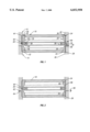
- FIG. 1 is a cross-sectional view of an embodiment of the invention.
- FIG. 2 is a cross-sectional view of an embodiment of the invention during the initial stages of installing an embodiment of a seal assembly of the invention.
- FIG. 1 illustrates a seal assembly 10 situated between an upper tubular member 12 and a lower tubular member 14.
- the seal assembly 10 includes a seal ring 16, a spacer 18, and an o-ring 20.
- the seal ring 16 includes an upper sealing lip 22 with frustoconical sealing flank 30 and a lower sealing lip 26 with frustoconical sealing flank 34.
- the sealing flank 30 mates with a frustoconical sealing surface 24 on an inner peripheral wall 32 of the member 12.
- the sealing flank 34 mates with a frustoconical sealing surface 28 on an inner peripheral wall 36 of the member 14. The interference fit between the flanks 24 and 28 and the surfaces 30 and 34, respectively, provide a tight seal between the members 12 and 14.
- the sealing lips 22 and 26 are spaced apart by a central convolution 38, which permits the sealing lips 22 and 26 to extend axially upon application of external pressure to the seal ring 16.
- the outer ends 40 and 42 of the sealing lips 22 and 26, respectively, may be made thicker to provide better resistance to axial deformation near the sealing contact region 44 and 46 and to minimize twisting of the lips.
- the spacer 18 is disposed in a groove 48 defined by the convolution 38.
- the spacer 18 is a metal ring which is split to facilitate installation in the groove 48.
- the spacer 18 includes a groove 50 which is shaped to receive the o-ring 20.
- the o-ring 20 is stretched around the spacer 18 to secure the spacer 18 to the seal ring 16.
- the clearances between the convolution 38 and the upper and lower surfaces 52 and 54 of the spacer 18 are controlled to a gap size that will prevent collapse of the convolution 38 to the extent that the convolution 38 is overstressed.
- the o-ring 20 cooperates with a groove 56 in the inner peripheral wall 32 of the member 12 to retain the seal assembly 10 in the member 12 when the member 12 is detached from the member 14.
- the seal ring 16 is made from metal, preferably a high-strength, corrosion-resistant metal (e.g. Nickel Alloy N07718)
- a soft metal plating may be provided on the seal ring 16 to enhance the sealing capability of the seal ring.
- a seal 58 is provided between the members 12 and 14 to provide a temporary seal between the members 12 and 14 for the purpose of testing the installation of the seal assembly 10. Pressure may be applied to the seal assembly 10 through the test port 60.
- the seal assembly 10 is initially attached to the member 12 by fitting the o-ring 20 into the groove 56 in the inner peripheral wall 32 of the member 12. Then the face 62 of the member 12 is advanced toward the face 64 of the member 14 until the sealing flanks 24 and 28 contact the sealing surfaces 30 and 34, respectively, as shown in FIG. 2.
- the sealing lips 22 and 26 also move radially inward such that the lips are placed in circumferential compression.
- the seal ring 16 has stored elastic force, both from the radial compression of the sealing lips 22 and 26 and the axial compression of the convolution 38. This force is directed toward achieving a tight sealing contact between the sealing flanks 30 and 34 of the seal ring 16 and the sealing surfaces 24 and 28 of the members 12 and 14, respectively.
- the amount of pressure energization of the seal ring 16 can be controlled by adjusting the flexibility of the convolution 38, the rigidity of the sealing lips 22 and 26, and the angle of the frustoconical flanks and surfaces.
- the ratio of the radial inward movement of the sealing lips 22 and 26 to the axial extension of the convolution 38 in each direction must be no more than the tangent of the angle of the frustoconical surface to ensure that the sealing force is not diminished.
- the members 12 and 14 can be put into service. Internal pressure acting in the seal ring 16 will cause the seal ring 16 to be energized radially outward against the sealing surfaces 24 and 28 while also causing the convolution 38 to move back to its normal position. The convolution 38 is again protected from being crushed by the spacer 18. This configuration will also adjust to compensate for any axial relative movement of the members 12 and 14 due to the resilience of the sealing lips 22 and 26 and the convolution 38.
Abstract
Description
Claims (16)
Priority Applications (1)
| Application Number | Priority Date | Filing Date | Title |
|---|---|---|---|
| US09/052,310 US6032958A (en) | 1998-03-31 | 1998-03-31 | Bi-directional pressure-energized metal seal |
Applications Claiming Priority (1)
| Application Number | Priority Date | Filing Date | Title |
|---|---|---|---|
| US09/052,310 US6032958A (en) | 1998-03-31 | 1998-03-31 | Bi-directional pressure-energized metal seal |
Publications (1)
| Publication Number | Publication Date |
|---|---|
| US6032958A true US6032958A (en) | 2000-03-07 |
Family
ID=21976760
Family Applications (1)
| Application Number | Title | Priority Date | Filing Date |
|---|---|---|---|
| US09/052,310 Expired - Lifetime US6032958A (en) | 1998-03-31 | 1998-03-31 | Bi-directional pressure-energized metal seal |
Country Status (1)
| Country | Link |
|---|---|
| US (1) | US6032958A (en) |
Cited By (13)
| Publication number | Priority date | Publication date | Assignee | Title |
|---|---|---|---|---|
| WO2002004783A1 (en) * | 2000-07-07 | 2002-01-17 | Zeroth Technology Limited | Deformable member |
| US6357760B1 (en) | 2000-05-19 | 2002-03-19 | Michael Doyle | Ring seal |
| US20030080516A1 (en) * | 2001-09-20 | 2003-05-01 | Zheng Qiu Shi | Fluid seal and method of using same |
| US6648335B1 (en) * | 1998-11-03 | 2003-11-18 | Michael D. Ezell | Metal-to-metal seal assembly for oil and gas production apparatus |
| US20070013146A1 (en) * | 2005-07-14 | 2007-01-18 | Gariepy James A | Sealing ring and method |
| US20080061510A1 (en) * | 2006-09-11 | 2008-03-13 | Schlumberger Technology Corporation | Forming a metal-to-metal seal in a well |
| US7407165B1 (en) * | 2000-04-04 | 2008-08-05 | Hutchinson Fts, Inc. | Composite sleeve for sealing a tubular coupling |
| US20080251256A1 (en) * | 2007-04-12 | 2008-10-16 | Baker Hughes Incorporated | Tieback seal system and method |
| US20080251261A1 (en) * | 2007-04-12 | 2008-10-16 | Baker Hughes Incorporated | Liner top packer seal assembly and method |
| GB2493094A (en) * | 2011-07-19 | 2013-01-23 | Vetco Gray Inc | A bi-directional pressure energised axial seal and a swivel connection application |
| US9169929B2 (en) * | 2013-03-15 | 2015-10-27 | Little Engine, LLC | Conformal wear-resistant seal |
| WO2020234610A1 (en) * | 2019-05-23 | 2020-11-26 | Subsea Technologies Limited | Gasket assembly and seal carrier |
| US20230358105A1 (en) * | 2022-05-03 | 2023-11-09 | Schlumberger Technology Corporation | Swivel system for downhole well tool orientation |
Citations (44)
| Publication number | Priority date | Publication date | Assignee | Title |
|---|---|---|---|---|
| US2988148A (en) * | 1958-12-22 | 1961-06-13 | Baker Oil Tools Inc | Subsurface well bore packing element |
| US3485142A (en) * | 1967-01-25 | 1969-12-23 | Parker Hannifin Corp | Liner seal for diesel engines and the like |
| US3784214A (en) * | 1971-10-18 | 1974-01-08 | J Tamplen | Seal that is responsive to either mechanical or pressure force |
| US4299332A (en) * | 1979-02-22 | 1981-11-10 | Hahn & Clay | Pressure vessel seal |
| US4361331A (en) * | 1979-10-22 | 1982-11-30 | Balzers Aktiengesellschaft fur Hochvakuumtechnic und Dunne Schichten | Seal for vacuum flange connections |
| US4390186A (en) * | 1982-02-04 | 1983-06-28 | Combustion Engineering, Inc. | Metal-to-metal ribbed seal |
| US4444400A (en) * | 1980-04-22 | 1984-04-24 | National Research Development Corporation | Seal assemblies and corrugated metal packer members therefor |
| US4486002A (en) * | 1982-09-24 | 1984-12-04 | Fmc Corporation | Combined metallic and flexible non-metallic pressure seal |
| US4545312A (en) * | 1984-08-06 | 1985-10-08 | Spencer Wright Industries, Inc. | Tufting machines |
| US4569540A (en) * | 1983-12-29 | 1986-02-11 | Beson Technology, Inc. | Piping suspender with metal-to-metal seal |
| US4601498A (en) * | 1982-11-15 | 1986-07-22 | Baker Oil Tools, Inc. | Deformable metal-to-metal seal |
| US4646845A (en) * | 1984-08-14 | 1987-03-03 | Cactus Wellhead Equipment Co., Inc. | Metal seal for wellhead apparatus |
| US4709725A (en) * | 1987-02-17 | 1987-12-01 | Vetco Gray, Inc. | Metal-to-metal seal structure |
| US4747606A (en) * | 1985-09-23 | 1988-05-31 | Vetco Gray Inc. | Bi-directional metal-to-metal seal |
| US4749047A (en) * | 1987-04-30 | 1988-06-07 | Cameron Iron Works Usa, Inc. | Annular wellhead seal |
| US4751965A (en) * | 1987-04-30 | 1988-06-21 | Cameron Iron Works Usa, Inc. | Wellhead seal assembly |
| US4771832A (en) * | 1987-12-09 | 1988-09-20 | Vetco Gray Inc. | Wellhead with eccentric casing seal ring |
| US4771828A (en) * | 1987-04-30 | 1988-09-20 | Cameron Iron Works, Usa, Inc. | Wellhead seals |
| US4791987A (en) * | 1987-04-30 | 1988-12-20 | Cameron Iron Works Usa, Inc. | Wellhead seal |
| US4813692A (en) * | 1987-01-22 | 1989-03-21 | Eg&G Pressure Science, Inc. | Pressure balanced S-seal |
| US4832381A (en) * | 1987-09-09 | 1989-05-23 | Cameron Iron Works Usa, Inc. | Seal |
| US4842061A (en) * | 1988-02-05 | 1989-06-27 | Vetco Gray Inc. | Casing hanger packoff with C-shaped metal seal |
| US4848777A (en) * | 1987-09-18 | 1989-07-18 | Fmc Corporation | Pressure energized/pressure intensified casing seal |
| US4911245A (en) * | 1989-03-10 | 1990-03-27 | Vetco Gray Inc. | Metal seal with soft inlays |
| US4911411A (en) * | 1989-04-10 | 1990-03-27 | Cryolab, Inc. | Clean gas valve using a metal-to-metal seal |
| US5026074A (en) * | 1989-06-30 | 1991-06-25 | Cooper Industries, Inc. | Annular metal-to-metal seal |
| US5044672A (en) * | 1990-03-22 | 1991-09-03 | Fmc Corporation | Metal-to-metal sealing pipe swivel joint |
| US5058906A (en) * | 1989-01-19 | 1991-10-22 | Vetco Gray Inc. | Integrally redundant seal |
| US5067734A (en) * | 1990-06-01 | 1991-11-26 | Abb Vetco Gray Inc. | Metal seal with grooved inlays |
| US5070942A (en) * | 1990-09-05 | 1991-12-10 | Cooper Industries, Inc. | Well tubing hanger sealing assembly |
| US5090871A (en) * | 1991-02-12 | 1992-02-25 | Systems Chemistry, Inc. | Junction assembly with leak detection means |
| US5174376A (en) * | 1990-12-21 | 1992-12-29 | Fmc Corporation | Metal-to-metal annulus packoff for a subsea wellhead system |
| US5183268A (en) * | 1991-04-30 | 1993-02-02 | Fmc Corporation | Metal-to-metal wellhead seal for rough casing |
| US5193616A (en) * | 1991-08-06 | 1993-03-16 | Cooper Industries, Inc. | Tubing hanger seal assembly |
| US5211226A (en) * | 1992-04-24 | 1993-05-18 | Otis Engineering Corporation | Metal-to-metal seal for oil well tubing string |
| US5224715A (en) * | 1991-01-17 | 1993-07-06 | Cooper Industries, Inc. | Supported-lip low interference metal stab seal |
| US5284205A (en) * | 1992-04-01 | 1994-02-08 | Halliburton Company | Metal to metal seal for well safety valve |
| US5370153A (en) * | 1993-12-16 | 1994-12-06 | Abb Vetco Gray Inc. | Metal seal hydraulic coupling |
| US5375812A (en) * | 1993-12-06 | 1994-12-27 | Abb Vetco Gray Inc. | Dynamic metal-to-metal seal |
| US5456314A (en) * | 1994-06-03 | 1995-10-10 | Abb Vetco Gray Inc. | Wellhead annulus seal |
| US5464063A (en) * | 1994-08-19 | 1995-11-07 | Abb Vetco Gray Inc. | Well assembly metal seal |
| US5662341A (en) * | 1996-03-19 | 1997-09-02 | Halliburton Company | Metal-to-metal seal assembly for oil and gas well production apparatus |
| US5941530A (en) * | 1995-02-10 | 1999-08-24 | Fmc Corporation | Unidirectional environment barrier seal for subsea wellhead equipment and valves |
| US5944319A (en) * | 1997-08-21 | 1999-08-31 | Vanoil Equipment Inc. | Method of forming a metal to metal seal between two confronting faces of pressure containing bodies and a metal to metal seal |
-
1998
- 1998-03-31 US US09/052,310 patent/US6032958A/en not_active Expired - Lifetime
Patent Citations (44)
| Publication number | Priority date | Publication date | Assignee | Title |
|---|---|---|---|---|
| US2988148A (en) * | 1958-12-22 | 1961-06-13 | Baker Oil Tools Inc | Subsurface well bore packing element |
| US3485142A (en) * | 1967-01-25 | 1969-12-23 | Parker Hannifin Corp | Liner seal for diesel engines and the like |
| US3784214A (en) * | 1971-10-18 | 1974-01-08 | J Tamplen | Seal that is responsive to either mechanical or pressure force |
| US4299332A (en) * | 1979-02-22 | 1981-11-10 | Hahn & Clay | Pressure vessel seal |
| US4361331A (en) * | 1979-10-22 | 1982-11-30 | Balzers Aktiengesellschaft fur Hochvakuumtechnic und Dunne Schichten | Seal for vacuum flange connections |
| US4444400A (en) * | 1980-04-22 | 1984-04-24 | National Research Development Corporation | Seal assemblies and corrugated metal packer members therefor |
| US4390186A (en) * | 1982-02-04 | 1983-06-28 | Combustion Engineering, Inc. | Metal-to-metal ribbed seal |
| US4486002A (en) * | 1982-09-24 | 1984-12-04 | Fmc Corporation | Combined metallic and flexible non-metallic pressure seal |
| US4601498A (en) * | 1982-11-15 | 1986-07-22 | Baker Oil Tools, Inc. | Deformable metal-to-metal seal |
| US4569540A (en) * | 1983-12-29 | 1986-02-11 | Beson Technology, Inc. | Piping suspender with metal-to-metal seal |
| US4545312A (en) * | 1984-08-06 | 1985-10-08 | Spencer Wright Industries, Inc. | Tufting machines |
| US4646845A (en) * | 1984-08-14 | 1987-03-03 | Cactus Wellhead Equipment Co., Inc. | Metal seal for wellhead apparatus |
| US4747606A (en) * | 1985-09-23 | 1988-05-31 | Vetco Gray Inc. | Bi-directional metal-to-metal seal |
| US4813692A (en) * | 1987-01-22 | 1989-03-21 | Eg&G Pressure Science, Inc. | Pressure balanced S-seal |
| US4709725A (en) * | 1987-02-17 | 1987-12-01 | Vetco Gray, Inc. | Metal-to-metal seal structure |
| US4749047A (en) * | 1987-04-30 | 1988-06-07 | Cameron Iron Works Usa, Inc. | Annular wellhead seal |
| US4751965A (en) * | 1987-04-30 | 1988-06-21 | Cameron Iron Works Usa, Inc. | Wellhead seal assembly |
| US4771828A (en) * | 1987-04-30 | 1988-09-20 | Cameron Iron Works, Usa, Inc. | Wellhead seals |
| US4791987A (en) * | 1987-04-30 | 1988-12-20 | Cameron Iron Works Usa, Inc. | Wellhead seal |
| US4832381A (en) * | 1987-09-09 | 1989-05-23 | Cameron Iron Works Usa, Inc. | Seal |
| US4848777A (en) * | 1987-09-18 | 1989-07-18 | Fmc Corporation | Pressure energized/pressure intensified casing seal |
| US4771832A (en) * | 1987-12-09 | 1988-09-20 | Vetco Gray Inc. | Wellhead with eccentric casing seal ring |
| US4842061A (en) * | 1988-02-05 | 1989-06-27 | Vetco Gray Inc. | Casing hanger packoff with C-shaped metal seal |
| US5058906A (en) * | 1989-01-19 | 1991-10-22 | Vetco Gray Inc. | Integrally redundant seal |
| US4911245A (en) * | 1989-03-10 | 1990-03-27 | Vetco Gray Inc. | Metal seal with soft inlays |
| US4911411A (en) * | 1989-04-10 | 1990-03-27 | Cryolab, Inc. | Clean gas valve using a metal-to-metal seal |
| US5026074A (en) * | 1989-06-30 | 1991-06-25 | Cooper Industries, Inc. | Annular metal-to-metal seal |
| US5044672A (en) * | 1990-03-22 | 1991-09-03 | Fmc Corporation | Metal-to-metal sealing pipe swivel joint |
| US5067734A (en) * | 1990-06-01 | 1991-11-26 | Abb Vetco Gray Inc. | Metal seal with grooved inlays |
| US5070942A (en) * | 1990-09-05 | 1991-12-10 | Cooper Industries, Inc. | Well tubing hanger sealing assembly |
| US5174376A (en) * | 1990-12-21 | 1992-12-29 | Fmc Corporation | Metal-to-metal annulus packoff for a subsea wellhead system |
| US5224715A (en) * | 1991-01-17 | 1993-07-06 | Cooper Industries, Inc. | Supported-lip low interference metal stab seal |
| US5090871A (en) * | 1991-02-12 | 1992-02-25 | Systems Chemistry, Inc. | Junction assembly with leak detection means |
| US5183268A (en) * | 1991-04-30 | 1993-02-02 | Fmc Corporation | Metal-to-metal wellhead seal for rough casing |
| US5193616A (en) * | 1991-08-06 | 1993-03-16 | Cooper Industries, Inc. | Tubing hanger seal assembly |
| US5284205A (en) * | 1992-04-01 | 1994-02-08 | Halliburton Company | Metal to metal seal for well safety valve |
| US5211226A (en) * | 1992-04-24 | 1993-05-18 | Otis Engineering Corporation | Metal-to-metal seal for oil well tubing string |
| US5375812A (en) * | 1993-12-06 | 1994-12-27 | Abb Vetco Gray Inc. | Dynamic metal-to-metal seal |
| US5370153A (en) * | 1993-12-16 | 1994-12-06 | Abb Vetco Gray Inc. | Metal seal hydraulic coupling |
| US5456314A (en) * | 1994-06-03 | 1995-10-10 | Abb Vetco Gray Inc. | Wellhead annulus seal |
| US5464063A (en) * | 1994-08-19 | 1995-11-07 | Abb Vetco Gray Inc. | Well assembly metal seal |
| US5941530A (en) * | 1995-02-10 | 1999-08-24 | Fmc Corporation | Unidirectional environment barrier seal for subsea wellhead equipment and valves |
| US5662341A (en) * | 1996-03-19 | 1997-09-02 | Halliburton Company | Metal-to-metal seal assembly for oil and gas well production apparatus |
| US5944319A (en) * | 1997-08-21 | 1999-08-31 | Vanoil Equipment Inc. | Method of forming a metal to metal seal between two confronting faces of pressure containing bodies and a metal to metal seal |
Cited By (32)
| Publication number | Priority date | Publication date | Assignee | Title |
|---|---|---|---|---|
| US6648335B1 (en) * | 1998-11-03 | 2003-11-18 | Michael D. Ezell | Metal-to-metal seal assembly for oil and gas production apparatus |
| US7407165B1 (en) * | 2000-04-04 | 2008-08-05 | Hutchinson Fts, Inc. | Composite sleeve for sealing a tubular coupling |
| US6357760B1 (en) | 2000-05-19 | 2002-03-19 | Michael Doyle | Ring seal |
| US7134506B2 (en) | 2000-07-07 | 2006-11-14 | Baker Hughes Incorporated | Deformable member |
| US20070029080A1 (en) * | 2000-07-07 | 2007-02-08 | Moyes Peter B | Deformable member |
| US6896049B2 (en) | 2000-07-07 | 2005-05-24 | Zeroth Technology Ltd. | Deformable member |
| US20050263296A1 (en) * | 2000-07-07 | 2005-12-01 | Moyes Peter B | Deformable member |
| EP1626157A1 (en) * | 2000-07-07 | 2006-02-15 | Zeroth Technology Limited | Deformable seal (div) |
| WO2002004783A1 (en) * | 2000-07-07 | 2002-01-17 | Zeroth Technology Limited | Deformable member |
| US7316271B2 (en) | 2000-07-07 | 2008-01-08 | Zeroth Technology Limited | Deformable member |
| US20030217844A1 (en) * | 2000-07-07 | 2003-11-27 | Moyes Peter Barnes | Deformable member |
| EP1798369A2 (en) * | 2000-07-07 | 2007-06-20 | Zeroth Technology Limited | Deformable seal (DIV II) |
| EP1798369A3 (en) * | 2000-07-07 | 2007-10-17 | Zeroth Technology Limited | Deformable seal (DIV II) |
| US20030080516A1 (en) * | 2001-09-20 | 2003-05-01 | Zheng Qiu Shi | Fluid seal and method of using same |
| US20070013146A1 (en) * | 2005-07-14 | 2007-01-18 | Gariepy James A | Sealing ring and method |
| US20080061510A1 (en) * | 2006-09-11 | 2008-03-13 | Schlumberger Technology Corporation | Forming a metal-to-metal seal in a well |
| US7510019B2 (en) | 2006-09-11 | 2009-03-31 | Schlumberger Technology Corporation | Forming a metal-to-metal seal in a well |
| US20080251256A1 (en) * | 2007-04-12 | 2008-10-16 | Baker Hughes Incorporated | Tieback seal system and method |
| US8561709B2 (en) | 2007-04-12 | 2013-10-22 | Baker Hughes Incorporated | Liner top packer seal assembly and method |
| US7735562B2 (en) * | 2007-04-12 | 2010-06-15 | Baker Hughes Incorporated | Tieback seal system and method |
| US20080251261A1 (en) * | 2007-04-12 | 2008-10-16 | Baker Hughes Incorporated | Liner top packer seal assembly and method |
| US9243711B2 (en) | 2011-07-19 | 2016-01-26 | Vetco Gray Inc. | Bi-directional pressure energized axial seal and a swivel connection application |
| CN103032047A (en) * | 2011-07-19 | 2013-04-10 | 韦特柯格雷公司 | A bi-directional pressure energised axial seal and a swivel connection application |
| GB2493094A (en) * | 2011-07-19 | 2013-01-23 | Vetco Gray Inc | A bi-directional pressure energised axial seal and a swivel connection application |
| AU2012205229B2 (en) * | 2011-07-19 | 2016-12-15 | Vetco Gray Inc. | Bi-directional pressure energized axial seal and a swivel connection application |
| GB2493094B (en) * | 2011-07-19 | 2018-05-16 | Vetco Gray Inc | Bi-directional pressure energized axial seal and a swivel connection application |
| US9169929B2 (en) * | 2013-03-15 | 2015-10-27 | Little Engine, LLC | Conformal wear-resistant seal |
| WO2020234610A1 (en) * | 2019-05-23 | 2020-11-26 | Subsea Technologies Limited | Gasket assembly and seal carrier |
| GB2599591A (en) * | 2019-05-23 | 2022-04-06 | Subsea Tech Limited | Gasket assembly and seal carrier |
| GB2599591B (en) * | 2019-05-23 | 2023-09-20 | Subsea Tech Limited | Gasket assembly and seal carrier |
| US20230358105A1 (en) * | 2022-05-03 | 2023-11-09 | Schlumberger Technology Corporation | Swivel system for downhole well tool orientation |
| US11821269B1 (en) * | 2022-05-03 | 2023-11-21 | Schlumberger Technology Corporation | Swivel system for downhole well tool orientation |
Similar Documents
| Publication | Publication Date | Title |
|---|---|---|
| US6032958A (en) | Bi-directional pressure-energized metal seal | |
| US6361049B1 (en) | Recessed groove/seal surface for seal effectiveness | |
| AU649485B2 (en) | Live load packing system | |
| US6007070A (en) | Pressure actuated packing assembly | |
| US6910692B2 (en) | Composite elastomeric seal for sealing fluid lines | |
| US5230498A (en) | Live load packing system | |
| US3218087A (en) | Foot seal | |
| CA2616361C (en) | Seal ring and method | |
| US7083170B2 (en) | Rod or piston primary seal | |
| JPH0215754B2 (en) | ||
| US4302020A (en) | Actuating sealing joint | |
| US20020140184A1 (en) | Metal-to-metal seal with soft metal insert | |
| US4555118A (en) | Seal construction for fluid swivel joints | |
| AU620005B2 (en) | Bellows seal with vibration damper | |
| JPS6213870A (en) | Packing assembly for fluid | |
| US5716083A (en) | Joint assembly and backing mechanism therefor | |
| US4486002A (en) | Combined metallic and flexible non-metallic pressure seal | |
| EP0110012B1 (en) | Valve assembly | |
| US6648337B1 (en) | Backup ring with controlled spacing | |
| US4511152A (en) | Self-reinforced face seal | |
| US4703914A (en) | Valve joint for fluid systems | |
| US7604056B2 (en) | Downhole valve and method of making | |
| US11629784B2 (en) | Sealing ring and use thereof | |
| US4289318A (en) | Hydraulic motor balancing ring seal | |
| EP0395713B1 (en) | Helical seal |
Legal Events
| Date | Code | Title | Description |
|---|---|---|---|
| AS | Assignment |
Owner name: HYDRIL COMPANY, TEXAS Free format text: ASSIGNMENT OF ASSIGNORS INTEREST;ASSIGNOR:FOWLER, JOHN H.;REEL/FRAME:009145/0579 Effective date: 19980327 |
|
| STCF | Information on status: patent grant |
Free format text: PATENTED CASE |
|
| FPAY | Fee payment |
Year of fee payment: 4 |
|
| AS | Assignment |
Owner name: HYDRIL COMPANY LP, TEXAS Free format text: ASSIGNMENT OF ASSIGNORS INTEREST;ASSIGNOR:HYDRIL COMPANY;REEL/FRAME:014499/0197 Effective date: 20020101 |
|
| AS | Assignment |
Owner name: HYDRIL COMPANY LP, TEXAS Free format text: ASSIGNMENT OF ASSIGNORS INTEREST;ASSIGNOR:HYDRIL COMPANY;REEL/FRAME:014763/0830 Effective date: 20030922 |
|
| FPAY | Fee payment |
Year of fee payment: 8 |
|
| REMI | Maintenance fee reminder mailed | ||
| AS | Assignment |
Owner name: HYDRIL GENERAL LLC, TEXAS Free format text: MERGER;ASSIGNOR:HYDRIL COMPANY LP;REEL/FRAME:020710/0717 Effective date: 20070629 Owner name: HYDRIL LLC, TEXAS Free format text: CHANGE OF NAME;ASSIGNOR:HDRYIL GENERAL LLC;REEL/FRAME:020710/0950 Effective date: 20070719 Owner name: HYDRIL GENERAL LLC,TEXAS Free format text: MERGER;ASSIGNOR:HYDRIL COMPANY LP;REEL/FRAME:020710/0717 Effective date: 20070629 Owner name: HYDRIL LLC,TEXAS Free format text: CHANGE OF NAME;ASSIGNOR:HDRYIL GENERAL LLC;REEL/FRAME:020710/0950 Effective date: 20070719 |
|
| AS | Assignment |
Owner name: HYDRIL USA MANUFACTURING LLC, TEXAS Free format text: ASSIGNMENT OF ASSIGNORS INTEREST;ASSIGNOR:HYDRIL LLC;REEL/FRAME:021050/0491 Effective date: 20080401 Owner name: HYDRIL USA MANUFACTURING LLC,TEXAS Free format text: ASSIGNMENT OF ASSIGNORS INTEREST;ASSIGNOR:HYDRIL LLC;REEL/FRAME:021050/0491 Effective date: 20080401 |
|
| FPAY | Fee payment |
Year of fee payment: 12 |