US6032919A - Gas flow proportioning and controlling valve system - Google Patents
Gas flow proportioning and controlling valve system Download PDFInfo
- Publication number
- US6032919A US6032919A US09/120,494 US12049498A US6032919A US 6032919 A US6032919 A US 6032919A US 12049498 A US12049498 A US 12049498A US 6032919 A US6032919 A US 6032919A
- Authority
- US
- United States
- Prior art keywords
- control valve
- valve
- flow control
- pressurized air
- opened
- Prior art date
- Legal status (The legal status is an assumption and is not a legal conclusion. Google has not performed a legal analysis and makes no representation as to the accuracy of the status listed.)
- Expired - Lifetime
Links
- 238000004891 communication Methods 0.000 claims abstract description 30
- 238000013022 venting Methods 0.000 claims description 5
- 238000011144 upstream manufacturing Methods 0.000 claims description 4
- 230000003247 decreasing effect Effects 0.000 claims description 3
- 230000001276 controlling effect Effects 0.000 description 7
- 230000008901 benefit Effects 0.000 description 4
- 238000004519 manufacturing process Methods 0.000 description 4
- 230000000717 retained effect Effects 0.000 description 4
- 230000001351 cycling effect Effects 0.000 description 3
- 238000010276 construction Methods 0.000 description 2
- 230000007423 decrease Effects 0.000 description 1
- 230000000694 effects Effects 0.000 description 1
- 238000005516 engineering process Methods 0.000 description 1
- 239000000463 material Substances 0.000 description 1
- 239000003129 oil well Substances 0.000 description 1
- 230000001105 regulatory effect Effects 0.000 description 1
Images

Classifications
-
- G—PHYSICS
- G05—CONTROLLING; REGULATING
- G05D—SYSTEMS FOR CONTROLLING OR REGULATING NON-ELECTRIC VARIABLES
- G05D7/00—Control of flow
- G05D7/03—Control of flow with auxiliary non-electric power
-
- F—MECHANICAL ENGINEERING; LIGHTING; HEATING; WEAPONS; BLASTING
- F16—ENGINEERING ELEMENTS AND UNITS; GENERAL MEASURES FOR PRODUCING AND MAINTAINING EFFECTIVE FUNCTIONING OF MACHINES OR INSTALLATIONS; THERMAL INSULATION IN GENERAL
- F16K—VALVES; TAPS; COCKS; ACTUATING-FLOATS; DEVICES FOR VENTING OR AERATING
- F16K31/00—Actuating devices; Operating means; Releasing devices
- F16K31/12—Actuating devices; Operating means; Releasing devices actuated by fluid
- F16K31/126—Actuating devices; Operating means; Releasing devices actuated by fluid the fluid acting on a diaphragm, bellows, or the like
- F16K31/1262—Actuating devices; Operating means; Releasing devices actuated by fluid the fluid acting on a diaphragm, bellows, or the like one side of the diaphragm being spring loaded
-
- Y—GENERAL TAGGING OF NEW TECHNOLOGICAL DEVELOPMENTS; GENERAL TAGGING OF CROSS-SECTIONAL TECHNOLOGIES SPANNING OVER SEVERAL SECTIONS OF THE IPC; TECHNICAL SUBJECTS COVERED BY FORMER USPC CROSS-REFERENCE ART COLLECTIONS [XRACs] AND DIGESTS
- Y10—TECHNICAL SUBJECTS COVERED BY FORMER USPC
- Y10T—TECHNICAL SUBJECTS COVERED BY FORMER US CLASSIFICATION
- Y10T137/00—Fluid handling
- Y10T137/8593—Systems
- Y10T137/87169—Supply and exhaust
- Y10T137/87217—Motor
Definitions
- gas flow control valve known as a "motor valve”
- the flow control valve commonly used is one that is spring biased to normally assumes a closed condition and requires a supply of external pressurized air above a predetermined level, such as 35 psi, to pneumatically cause opening of the flow control valve against the spring bias. Once the flow control valve is opened, any further supply of external pressurized air to the flow control valve can be cutoff, since the pressurized air already supplied to pneumatically actuate the flow control valve will be retained in it and hold it in the opened condition. To close the flow control valve, the pressurized air retained therein merely is vented off to the atmosphere.
- This quantity of gas and oil can be viewed as an "off the chart" giveaway by the well producer to the gas and oil company purchasing the production. Also, in order to maximize product sales income from a well, it desirable to regulate the velocity of flow of gas and oil from the well so that a separator downstream of the flow control valve can function properly to separate oil from the gas and thereby prevent oil from being suspended and carried with the gas to the sales line and, in effect, given away free to the gas company buying only the gas from the well.
- the present invention provides a gas flow proportioning and controlling valve system designed to satisfy the aforementioned need.
- the proportioning and controlling valve system of the present invention provides a solution to the above-described problem by incorporating two commerically-available solenoid-type latching valves which are low in cost and simple in construction and require low energy to operate in that energy is only required to switch the latching valves between their opened and closed conditions where they are then retained by internal permanent magnets at the one or the other of the respective opened and closed conditions.
- the latching valves are connected to one another and one of the latching valves is connected to a flow control valve and a source of pressurized air flow in an arrangement that by coordinated switching of the latching valves between their respective opened and closed conditions will cause or permit pneumatic actuation of the flow control valve to selected intermediate positions between fully closed and opened positions so as to thereby provide a proportionate or percentage opening of the flow control valve and change in the magnitude of gas flow pressure and velocity to the sales line.
- the present invention is directed to a gas flow proportioning and controlling valve system which comprises: (a) a source of pressurized air flow; (b) a flow control valve capable of pneumatic actuation between fully opened and closed positions corresponding permitting and preventing gas flow therethrough and to selected intermediate positions progressively increasing and decreasing between the fully closed to opened positions to provide a proportionately greater and lesser opening of the flow control valve and magnitude of the pressure and velocity of gas flow therethrough; (c) a first latching valve connected to the source of pressurized air flow, to the flow control valve and to a vent line and being switchable between an opened condition in which communication of pressurized air flow is only provided therethrough from the source of pressurized air flow to the flow control valve and a closed condition in which communication of pressurized air flow is only provided therethrough from the flow control valve to the vent line; (d) a second latching valve connected to the vent line from the first latching valve and to atmosphere and being switchable between an opened condition in which communication of pressurized air flow is only provided therethrough from the
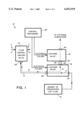
- FIG. 1 is a diagrammatic representation of a gas flow proportioning and controlling valve system of the present invention utilizing a pair of latching valves with a flow control valve.
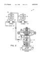
- FIG. 2 is a schematic representation of one practical implementation of the valve system of the present invention showing the flow control valve interposed in a gas flow line and actuated to an opened position.
- FIG. 3 is a schematic representation of the valve system similar to that of FIG. 2 but showing the flow control valve actuated to a closed position.
- valve system 10 for proportioning and controlling flow in a gas flow line L, such as a gas sales line of a gas-producing well (not shown).
- the valve system 10 basically includes a source 12 of pressurized air flow, a motor or flow control valve 14 interposed in the gas flow line L between an upstream portion U and a downstream portion D thereof, first and second latching valves 16, 18 employed with the flow control valve 14 and being switchable between only two, namely opened and closed, conditions, and a control mechanism 20 operable to control switching of the first and second latching valves 16, 18 between their two conditions.
- the motor or flow control valve 14 is capable of pneumatic actuation between fully opened and closed positions corresponding permitting and preventing gas flow therethrough and to selected intermediate positions between the fully closed position and opened position to provide a proportionately greater and lesser opening of the flow control valve 14 and magnitude of the pressure and velocity of gas flow therethrough.
- the first latching valve 16 is connected to the source 12 of pressurized air flow, to the flow control valve 14 and to a vent line 22.
- the first latching valve 16 is switchable between an opened condition in which communication of pressurized air flow is only provided therethrough from the source 12 of pressurized air flow to the flow control valve 14 and a closed condition in which communication of pressurized air flow is only provided therethrough from the flow control valve 14 to the vent line 22.
- the second latching valve 18 is connected to the vent line 22 from the first latching valve 16 and to atmosphere.
- the second latching valve 18 is switchable between an opened condition in which communication of pressurized air flow is only provided therethrough from the vent line 22 to atmosphere and a closed condition wherein communication of pressurized air flow is blocked therethrough.
- the latching valves 16, 18 can be implemented as two commerically-available solenoid type latching valves which are low in cost and simple in construction and require low electrical energy to operate. Electrical energy is only required to switch the latching valves 16, 18 between their two, opened and closed, conditions, with a permanent magnet utilized internally by each to retain the latching valve 16, 18 at the one or the other of its respective opened and closed conditions.
- the control mechanism 20 is a suitable electronic device operable to cause selective and separate switching of the first and second latching valves 16, 18 between their respective opened and closed conditions in a coordinated manner which causes pneumatic actuation of the flow control valve 14 to any of the selected intermediate positions between the fully opened and closed positions.
- the control mechanism 20 applies first and second electrical pulses respectively to the first and second latching valves 16, 18 to actuate them between their opened and closed conditions.
- practical design of an electronic device to implement the control mechanism 20 need not be described in detail herein, such being well within the capability of one of ordinary skill in the art without the exercise of undue experimentation.
- the first and second latching valves 16, 18, must be capable of switching between their respective opened and closed conditions in a fraction of the time it takes the pneumatically actuated motor or flow control valve 14 to change between its closed and fully opened positions.
- electrically-operated solenoid type of latching valves 16, 18 such as the ones commercially-available from EEMCO a division of Datron System, Inc., will meet this requirement.
- the first latching valve 16 has a first port 24 connected to the source 12 of pressurized air flow, a second port 26 connected to a port 28 of the flow control valve 14, and a third port 30 connected the vent line 22.
- the second latching valve 18 has a first port 32 connected to the vent line 22 from the first latching valve 16 and a second port 34 venting to atmosphere.
- the first and second latching valves 16, 18 are actuatable between opened and closed positions by application of respective first and second electrical pulses thereto by operation of the control mechanism 20.
- the flow control valve 14 can be moved to and placed at any selected intermediate "percentage” or partially opened position between its closed position and fully opened position and thereby proportion the flow pressure from the wellhead to the sales line.
- a pressure transducer (not shown) can be used downstream of the flow control valve 14 to monitor and determine what is the value of the flow pressure being released into the sales line.
- the valve system 10 described above permits the percentage opening of the flow control valve 14 so as to control and regulate the flow pressure and velocity of the oil and gas downstream of the flow control valve 14. Not only does this avoid “off the chart” and gas suspended oil giveaways to the gas company purchaser, the valve system 10 also prolongs the productive life of a well by permitting the well producer to be able to constantly monitor the velocity of gas from the well so as to determine when it begins a decline trendline indicating that well is starting to die.
- the percentage opening of the flow control valve 14 can be adjusted in order to boost the flow velocity and prolong the productive life of the well.
- valve system 10 of the invention has been described in its preferred application with a gas and oil production wellhead, it can be readily appreciated that there are other applications for the system.
- the valve system 10 can be employed whenever a preset biasing force or pressure is used to hold a mechanism at a first home position and an external supply of pressurized air is used to overcome the biasing force to drive the mechanism toward a second extreme position.
- the use of the valve system 10 of the invention will permit the mechanism to be incrementally moved and retained at any intermediate position between the two extreme positions.
Landscapes
- Engineering & Computer Science (AREA)
- General Engineering & Computer Science (AREA)
- Power Engineering (AREA)
- Physics & Mathematics (AREA)
- General Physics & Mathematics (AREA)
- Automation & Control Theory (AREA)
- Mechanical Engineering (AREA)
- Fluid-Pressure Circuits (AREA)
Abstract
Description
Claims (15)
Priority Applications (1)
| Application Number | Priority Date | Filing Date | Title |
|---|---|---|---|
| US09/120,494 US6032919A (en) | 1997-07-24 | 1998-07-21 | Gas flow proportioning and controlling valve system |
Applications Claiming Priority (2)
| Application Number | Priority Date | Filing Date | Title |
|---|---|---|---|
| US5368397P | 1997-07-24 | 1997-07-24 | |
| US09/120,494 US6032919A (en) | 1997-07-24 | 1998-07-21 | Gas flow proportioning and controlling valve system |
Publications (1)
| Publication Number | Publication Date |
|---|---|
| US6032919A true US6032919A (en) | 2000-03-07 |
Family
ID=26732133
Family Applications (1)
| Application Number | Title | Priority Date | Filing Date |
|---|---|---|---|
| US09/120,494 Expired - Lifetime US6032919A (en) | 1997-07-24 | 1998-07-21 | Gas flow proportioning and controlling valve system |
Country Status (1)
| Country | Link |
|---|---|
| US (1) | US6032919A (en) |
Cited By (6)
| Publication number | Priority date | Publication date | Assignee | Title |
|---|---|---|---|---|
| US20050178543A1 (en) * | 2004-02-18 | 2005-08-18 | Giacomino Jeffrey L. | Data logger plunger |
| US20070175640A1 (en) * | 2006-01-31 | 2007-08-02 | Atencio Michael E | Multi-Well Controller |
| US20100001087A1 (en) * | 2008-07-03 | 2010-01-07 | Mike Gum | Variable output heating control system |
| US20100170574A1 (en) * | 2007-05-25 | 2010-07-08 | Liebherr-Aerospace Toulouse Sas | Gas mixing pump with variable injection section |
| US10578065B1 (en) * | 2018-10-30 | 2020-03-03 | Taiwan Chelic Co., Ltd. | Two-stage intake and two-stage discharge structure of electrically controlled proportional valve |
| US11953098B2 (en) * | 2020-06-30 | 2024-04-09 | Ademco Inc. | Inlet controlled regulating valve |
Citations (12)
| Publication number | Priority date | Publication date | Assignee | Title |
|---|---|---|---|---|
| US2662542A (en) * | 1951-12-22 | 1953-12-15 | Gilbert & Barker Mfg Co | Hydraulic control device for highpressure liquid-fuel-supply pumps of pressure-atomizing oil burners |
| US3036585A (en) * | 1958-08-08 | 1962-05-29 | Sun Oil Co | Fuel dispensing system |
| US3219046A (en) * | 1960-08-25 | 1965-11-23 | Foxboro Co | Fluid ratio control |
| US3415264A (en) * | 1962-12-06 | 1968-12-10 | Plenty And Son Ltd | Blenders for blending two or more liquids |
| US3437312A (en) * | 1966-11-01 | 1969-04-08 | Bell Aerospace Corp | Electrical signal and monitoring apparatus for redundant control system |
| US3474815A (en) * | 1965-12-17 | 1969-10-28 | Crown Cork & Seal Co | Fluid proportioning and blending system |
| US3581759A (en) * | 1967-05-23 | 1971-06-01 | Charles Clifford Veale | Control means for proportioning and modulating fluid flow rates to regulate pressures and temperatures |
| US3705792A (en) * | 1971-06-14 | 1972-12-12 | Owens Illinois Inc | Liquid flow proportioning system for metering into a glass batch |
| US4183384A (en) * | 1978-01-18 | 1980-01-15 | Air Products And Chemicals, Inc. | Process and apparatus for blending fluids to maintain concentration of one below a predetermined maximum |
| US4241750A (en) * | 1978-11-27 | 1980-12-30 | Kabushiki Kaisha Cosmo Keiki | Pressure setting device |
| US4961441A (en) * | 1989-11-13 | 1990-10-09 | Salter Stuart C | Method and system for controlling a pressure regulator |
| US5042775A (en) * | 1988-05-27 | 1991-08-27 | Koppens Automatic Fabrieken B. V. | Stop valve and control/mixing system for fluids |
-
1998
- 1998-07-21 US US09/120,494 patent/US6032919A/en not_active Expired - Lifetime
Patent Citations (12)
| Publication number | Priority date | Publication date | Assignee | Title |
|---|---|---|---|---|
| US2662542A (en) * | 1951-12-22 | 1953-12-15 | Gilbert & Barker Mfg Co | Hydraulic control device for highpressure liquid-fuel-supply pumps of pressure-atomizing oil burners |
| US3036585A (en) * | 1958-08-08 | 1962-05-29 | Sun Oil Co | Fuel dispensing system |
| US3219046A (en) * | 1960-08-25 | 1965-11-23 | Foxboro Co | Fluid ratio control |
| US3415264A (en) * | 1962-12-06 | 1968-12-10 | Plenty And Son Ltd | Blenders for blending two or more liquids |
| US3474815A (en) * | 1965-12-17 | 1969-10-28 | Crown Cork & Seal Co | Fluid proportioning and blending system |
| US3437312A (en) * | 1966-11-01 | 1969-04-08 | Bell Aerospace Corp | Electrical signal and monitoring apparatus for redundant control system |
| US3581759A (en) * | 1967-05-23 | 1971-06-01 | Charles Clifford Veale | Control means for proportioning and modulating fluid flow rates to regulate pressures and temperatures |
| US3705792A (en) * | 1971-06-14 | 1972-12-12 | Owens Illinois Inc | Liquid flow proportioning system for metering into a glass batch |
| US4183384A (en) * | 1978-01-18 | 1980-01-15 | Air Products And Chemicals, Inc. | Process and apparatus for blending fluids to maintain concentration of one below a predetermined maximum |
| US4241750A (en) * | 1978-11-27 | 1980-12-30 | Kabushiki Kaisha Cosmo Keiki | Pressure setting device |
| US5042775A (en) * | 1988-05-27 | 1991-08-27 | Koppens Automatic Fabrieken B. V. | Stop valve and control/mixing system for fluids |
| US4961441A (en) * | 1989-11-13 | 1990-10-09 | Salter Stuart C | Method and system for controlling a pressure regulator |
Non-Patent Citations (4)
| Title |
|---|
| EEMCO, Division of Datron Systems Inc., Two and Three Way Latching Valves, 2 pages, No Date. * |
| EEMCO, Division of Datron Systems Inc., Two and Three-Way Latching Valves, 2 pages, No Date. |
| Kimray, Inc., 1 & 2 High Pressure Motor Valve, p.E1:10.1 dated Jan. 1994. * |
| Kimray, Inc., 1"& 2" High Pressure Motor Valve, p.E1:10.1 dated Jan. 1994. |
Cited By (11)
| Publication number | Priority date | Publication date | Assignee | Title |
|---|---|---|---|---|
| US20050178543A1 (en) * | 2004-02-18 | 2005-08-18 | Giacomino Jeffrey L. | Data logger plunger |
| US20080110617A1 (en) * | 2004-02-18 | 2008-05-15 | Giacomino Jeffrey L | Method and Apparatus for Logging Downhole Data |
| US7597143B2 (en) | 2004-02-18 | 2009-10-06 | Production Control Services, Inc. | Method and apparatus for logging downhole data |
| US7690425B2 (en) | 2004-02-18 | 2010-04-06 | Production Control Services, Inc. | Data logger plunger and method for its use |
| US20070175640A1 (en) * | 2006-01-31 | 2007-08-02 | Atencio Michael E | Multi-Well Controller |
| US7950464B2 (en) | 2006-01-31 | 2011-05-31 | Production Control Services, Inc. | Multi-well controller |
| US20100170574A1 (en) * | 2007-05-25 | 2010-07-08 | Liebherr-Aerospace Toulouse Sas | Gas mixing pump with variable injection section |
| US20100001087A1 (en) * | 2008-07-03 | 2010-01-07 | Mike Gum | Variable output heating control system |
| US9317046B2 (en) * | 2008-07-03 | 2016-04-19 | Mike Gum | Variable output heating control system |
| US10578065B1 (en) * | 2018-10-30 | 2020-03-03 | Taiwan Chelic Co., Ltd. | Two-stage intake and two-stage discharge structure of electrically controlled proportional valve |
| US11953098B2 (en) * | 2020-06-30 | 2024-04-09 | Ademco Inc. | Inlet controlled regulating valve |
Similar Documents
| Publication | Publication Date | Title |
|---|---|---|
| WO2004063607A3 (en) | Actuator for well-head valve or other similar applications and system incorporating same | |
| GB2369637A (en) | Apparatus and method for controlling fluid flow | |
| US4240463A (en) | Safety valve actuator and pilot system | |
| US6032919A (en) | Gas flow proportioning and controlling valve system | |
| EP1031792A3 (en) | Gas control device with a direct modulating gas control valve | |
| DE2055878A1 (en) | Pressure control device | |
| WO1996019689A3 (en) | Valve arrangement, in particular for pneumatic control systems | |
| EP0846902B1 (en) | Electro-pneumatic valve | |
| AU2242401A (en) | A heat exchanger arrangement and method for control of a fluid through a heat exchanger arrangement | |
| DE102008028189A1 (en) | Electropneumatic valve | |
| ES8205989A1 (en) | Solenoid valve | |
| CN203477544U (en) | Constant temperature/constant pressure intelligent adjusting valve | |
| JPS6129913A (en) | Flow controller | |
| US5038813A (en) | Pneumatic starter device | |
| DE102008028192A1 (en) | Electropneumatic valve | |
| EP1586777B1 (en) | Kit for proportional valve and valve assembled therewith | |
| CN2158470Y (en) | Dust-proof electromagnetic valve for mining use | |
| CN2407199Y (en) | Improved fluid pressure regulating device | |
| CN207728981U (en) | A kind of quick response safety-valve | |
| JP2860606B2 (en) | Self-powered pressure regulating valve device | |
| EP0134744A3 (en) | Proportional follower spool valve system | |
| GB881125A (en) | Improvements in valves for controlling fluids | |
| CN201326783Y (en) | Pneumatic double-adjusting fuel gas valve | |
| KR20050065944A (en) | Load limit and metering manifold of servo actuator for airframe structural test | |
| JPH0333576A (en) | High pressure air switching valve |
Legal Events
| Date | Code | Title | Description |
|---|---|---|---|
| STCF | Information on status: patent grant |
Free format text: PATENTED CASE |
|
| AS | Assignment |
Owner name: U.S. BANK NATIONAL ASSOCIATION, MINNESOTA Free format text: SECURITY INTEREST;ASSIGNOR:PRODUCTION CONTROL SERVICES, INC.;REEL/FRAME:011213/0055 Effective date: 20001002 |
|
| FEPP | Fee payment procedure |
Free format text: PAYOR NUMBER ASSIGNED (ORIGINAL EVENT CODE: ASPN); ENTITY STATUS OF PATENT OWNER: LARGE ENTITY |
|
| FPAY | Fee payment |
Year of fee payment: 4 |
|
| AS | Assignment |
Owner name: PRODUCTION CONTROL SERVICES, INC., COLORADO Free format text: ASSIGNMENT OF ASSIGNORS INTEREST;ASSIGNORS:GIACOMINO, JEFFREY L.;VICTOR, BRUCE M.;REEL/FRAME:014653/0001 Effective date: 20040518 |
|
| AS | Assignment |
Owner name: PRODUCTION CONTROL SERVICES GROUP, INC., COLORADO Free format text: MERGER;ASSIGNOR:PRODUCTION CONTROL SERVICES, INC.;REEL/FRAME:014718/0022 Effective date: 20040602 Owner name: PRODUCTION CONTROL SERVICES, INC., COLORADO Free format text: CHANGE OF NAME;ASSIGNOR:PRODUCTION CONTROL SERVICES GROUP, INC.;REEL/FRAME:014718/0059 Effective date: 20040604 |
|
| AS | Assignment |
Owner name: PRODUCTION CONTROL SERVICES, INC., COLORADO Free format text: DISCHARGE AND RELEASE OF SECURITY INTEREST;ASSIGNOR:U.S. BANK NATIONAL ASSOCIATION;REEL/FRAME:015460/0422 Effective date: 20040524 |
|
| AS | Assignment |
Owner name: COLORADO BUSINESS BANK, COLORADO Free format text: NOTICE OF GRANT OF SECURITY INTEREST;ASSIGNOR:PRODUCTION CONTROL SERVICES, INC.;REEL/FRAME:015487/0752 Effective date: 20040601 |
|
| AS | Assignment |
Owner name: PRODUCTION CONTROL SERVICES, INC., COLORADO Free format text: RELEASE;ASSIGNOR:US BANK NATIONAL ASSOCIATION;REEL/FRAME:015552/0484 Effective date: 20040702 |
|
| FEPP | Fee payment procedure |
Free format text: PAYOR NUMBER ASSIGNED (ORIGINAL EVENT CODE: ASPN); ENTITY STATUS OF PATENT OWNER: LARGE ENTITY Free format text: PAYER NUMBER DE-ASSIGNED (ORIGINAL EVENT CODE: RMPN); ENTITY STATUS OF PATENT OWNER: LARGE ENTITY |
|
| FEPP | Fee payment procedure |
Free format text: PAYOR NUMBER ASSIGNED (ORIGINAL EVENT CODE: ASPN); ENTITY STATUS OF PATENT OWNER: LARGE ENTITY Free format text: PAYER NUMBER DE-ASSIGNED (ORIGINAL EVENT CODE: RMPN); ENTITY STATUS OF PATENT OWNER: LARGE ENTITY |
|
| FEPP | Fee payment procedure |
Free format text: PAT HOLDER NO LONGER CLAIMS SMALL ENTITY STATUS, ENTITY STATUS SET TO UNDISCOUNTED (ORIGINAL EVENT CODE: STOL); ENTITY STATUS OF PATENT OWNER: LARGE ENTITY |
|
| REFU | Refund |
Free format text: REFUND - PAYMENT OF MAINTENANCE FEE, 8TH YR, SMALL ENTITY (ORIGINAL EVENT CODE: R2552); ENTITY STATUS OF PATENT OWNER: LARGE ENTITY |
|
| AS | Assignment |
Owner name: MERRILL LYNCH CAPITAL, A DIVISION OF MERRILL LYNCH Free format text: SECURITY AGREEMENT;ASSIGNOR:PRODUCTION CONTROL SERVICES, INC.;REEL/FRAME:018731/0991 Effective date: 20070105 |
|
| AS | Assignment |
Owner name: PRODUCTION CONTROL SERVICES, INC., COLORADO Free format text: RELEASE BY SECURED PARTY;ASSIGNOR:COLORADO BUSINESS BANK;REEL/FRAME:018816/0039 Effective date: 20070122 |
|
| FPAY | Fee payment |
Year of fee payment: 8 |
|
| REMI | Maintenance fee reminder mailed | ||
| AS | Assignment |
Owner name: GENERAL ELECTRIC CAPITAL CORPORATION, AS ADMINISTR Free format text: AMENDMENT AND ASSIGNMENT OF PATENT SECURITY AGREEMENT;ASSIGNOR:MERRILL LYNCH BUSINESS FINANCIAL SERVICES, INC., AS RESIGNING ADMINISTRATIVE AGENT;REEL/FRAME:020638/0368 Effective date: 20080215 |
|
| FPAY | Fee payment |
Year of fee payment: 12 |
|
| AS | Assignment |
Owner name: PRODUCTION CONTROL SERVICES, INC., COLORADO Free format text: RELEASE BY SECURED PARTY;ASSIGNOR:GENERAL ELECTRIC CAPITAL CORPORATION, AS ADMINISTRATIVE AGENT;REEL/FRAME:028109/0402 Effective date: 20120425 |
|
| AS | Assignment |
Owner name: PCS FERGUSON, INC., COLORADO Free format text: CHANGE OF NAME;ASSIGNOR:PRODUCTION CONTROL SERVICES, INC.;REEL/FRAME:034630/0529 Effective date: 20130701 |