US6032906A - Point drive unit - Google Patents
Point drive unit Download PDFInfo
- Publication number
- US6032906A US6032906A US09/077,158 US7715898A US6032906A US 6032906 A US6032906 A US 6032906A US 7715898 A US7715898 A US 7715898A US 6032906 A US6032906 A US 6032906A
- Authority
- US
- United States
- Prior art keywords
- cylinder
- housing
- drive unit
- rails
- point drive
- Prior art date
- Legal status (The legal status is an assumption and is not a legal conclusion. Google has not performed a legal analysis and makes no representation as to the accuracy of the status listed.)
- Expired - Lifetime
Links
- 239000012530 fluid Substances 0.000 claims abstract description 19
- 230000008878 coupling Effects 0.000 claims abstract description 12
- 238000010168 coupling process Methods 0.000 claims abstract description 12
- 238000005859 coupling reaction Methods 0.000 claims abstract description 12
- 241000239290 Araneae Species 0.000 description 1
- 239000004411 aluminium Substances 0.000 description 1
- 229910052782 aluminium Inorganic materials 0.000 description 1
- XAGFODPZIPBFFR-UHFFFAOYSA-N aluminium Chemical compound [Al] XAGFODPZIPBFFR-UHFFFAOYSA-N 0.000 description 1
- 239000011521 glass Substances 0.000 description 1
- 230000002452 interceptive effect Effects 0.000 description 1
- 229910052751 metal Inorganic materials 0.000 description 1
- 239000002184 metal Substances 0.000 description 1
- 239000002480 mineral oil Substances 0.000 description 1
- 235000010446 mineral oil Nutrition 0.000 description 1
- 239000004033 plastic Substances 0.000 description 1
- 239000004810 polytetrafluoroethylene Substances 0.000 description 1
- 229920001343 polytetrafluoroethylene Polymers 0.000 description 1
- 238000013022 venting Methods 0.000 description 1
Images


Classifications
-
- B—PERFORMING OPERATIONS; TRANSPORTING
- B61—RAILWAYS
- B61L—GUIDING RAILWAY TRAFFIC; ENSURING THE SAFETY OF RAILWAY TRAFFIC
- B61L5/00—Local operating mechanisms for points or track-mounted scotch-blocks; Visible or audible signals; Local operating mechanisms for visible or audible signals
- B61L5/06—Electric devices for operating points or scotch-blocks, e.g. using electromotive driving means
Definitions
- the present invention relates to point drive units for driving railway points (switches) to move.
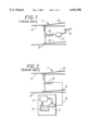
- certain railway points 1 are conventionally driven by a pneumatic cylinder 2 installed generally centrally between two of the rails 3 of the railway track.
- the cylinder is controlled remotely via pipes 4.
- An alternative arrangement, which is illustrated in FIG. 2, is to drive the points using a hydraulically self-contained unit, which requires no remote hydraulic supply.
- the unit shown schematically in FIG. 2 has an electrically driven hydraulic pump 5 which pressurises fluid from a local reservoir 6 to drive a hydraulic cylinder 7.
- the unit is too large to fit between the rails so the cylinder is coupled to the points via a linkage shown schematically at 8.
- the drive unit installed entirely in the space between the rails of the track.
- the space between the rails is limited, particularly in multi-rail railways, so any unit that is to fit between the rails must be very compact.
- the points typically have a connecting rod 9 which lies generally parallel with and generally centrally between two of the rails.
- the natural approach in designing units to fit between the rails has therefore been to try to mount a cylinder in line with the connecting rod 9 as has previously been the case in systems like that shown in FIG. 1.
- locating the cylinder in this way has prevented the other components of a unit more complex than that shown in FIG. 1 being arranged so that the unit can fit between the rails.
- FR-A-2 649 060 discloses a point drive unit in which a cylinder is mounted laterally offset to one side of a central longitudinal axis of a housing including control means.
- An electro-hydraulic control is mounted at a location laterally adjacent the cylinder but the cylinder is still in line with the connecting rod of the points.
- a point drive unit for driving railway points to move via a connecting means of the points comprising a connecting rod located generally centrally between and lying parallel with two of the rails of the railway track, the unit comprising:
- a housing adapted to be installed between said two of the rails, the housing having a central longitudinal axis which is generally centrally located between said two of the rails and generally parallel with them in use of the unit;
- a cylinder enclosing a piston which is moveable in a direction parallel to said longitudinal axis of the housing for driving the points, the cylinder being mounted within the housing at a location laterally offset to one side of said longitudinal axis of the housing;
- control means mounted within the housing at a location laterally adjacent the cylinder for controlling the supply of fluid to the cylinder to control the movement of the piston;
- the drive unit With the cylinder laterally offset to one side of the housing the drive unit can be made more compact than before.
- control means comprises one or more of:
- a pump suitably driven by an electric motor, for pressurising fluid from the reservoir;
- valve suitably actuable by electrical signals, for directing fluid to either end of the cylinder
- At least one check valve for locking the piston in place when required.
- Items of the control means may be provided in a manifold.
- the housing is preferably adapted to be installed between the rails by being of a such a size that it can be installed between the rails without interfering with other equipment and/or by being provided with fixing means located to allow it to be fixed securely in place between the rails.
- the housing is adapted to be installed so that its central longitudinal axis (that is the axis half way between its outermost lateral walls) is generally centrally between said two of the rails and generally parallel with them, the central longitudinal axis of the cylinder then being offset laterally from the central longitudinal axis of the housing.
- Said two of the rails are preferably adjacent rails to each other.
- the offset coupling comprises an arm for linking the connecting means to the piston so that the proximal end of the connecting means (that is the end nearest the drive unit) and the distal end of the piston (that is the end nearest the connecting means) are spaced apart in a direction parallel to the track.
- FIGS. 1 and 2 show, schematically, conventional point drive units
- FIG. 3 is a side view of railway point apparatus and a point drive unit according to an example of the present invention, with one side of the outer cover of the drive unit removed for clarity;
- FIG. 4 is a plan view of point apparatus and the point drive unit with the top of the outer cover removed for clarity;
- FIG. 5 is an end view on arrow A in FIG. 4 with the end of the outer cover and part of a handle removed for clarity;
- FIG. 6 shows the hydraulic circuit of the point drive unit.
- FIGS. 3 to 6 show a point drive unit 10.
- a motor assembly 13 which drives a pump 14; a manifold block 15 which is supplied by the pump with pressurised hydraulic fluid (e.g. mineral oil) from a reservoir or tank 16; a control valve 17 for controlling the hydraulic output from the manifold; and a double-acting hydraulic cylinder 18 whose piston 19 is coupled via an offset coupling 20 to the connecting rod 21 of the railway points.
- the cylinder 18 is laterally offset to one side of the housing. This leaves a large region of the housing free for the other components of the point drive unit, which are mounted laterally adjacent the cylinder.
- the point drive unit comprises a base plate 11 with handles 22 fixed at each end.
- fixing means comprising through holes 23 in the base plate to allow it to be installed with bolts and/or quick release fastenings between the rails 3 of a railway, preferably generally centrally between the rails that are immediately on either side of it.
- Covering the unit is an outer cover 12 of plastic-coated sheet metal. The cover can be padlocked to the base plate for security.
- the manifold block 15 which is machined from aluminium, acts as the core of the unit, with the other major components mounted to it.
- the motor 13 is a series-wound d.c. motor rated at 110 V and drawing 7 A at its operating speed.
- the tank is filled through a cap 36 which incorporates a spring-loaded ball valve. When the cap is closed this valve will allow air to vent out of the tank under slight pressure, but will impede the escape of fluid. Ingress of air is prevented by the valve, and this ensures that no dirt may enter the system.
- a sight-glass giving a direct view of the fluid level.
- the cylinder is connected to the manifold by pipes 24.
- the pump 14 pressurises fluid from the tank 16 and passes the pressurised fluid through a pressure filter 25.
- a pilot-operated pressure relief valve 26 venting to the tank is provided in case of over pressure.
- From the filter 25 the fluid passes to the solenoid-actuated control valve 17. In its default setting this disconnects the pump from the remainder of the circuit but it can be actuated electrically to direct the fluid in either direction to the cylinder 18.
- the control valve is not actuated the cylinder 18 is locked by pilot-operated check valves 27.
- a manually operated bypass valve 28 is provided to allow the check valves 27 to be bypassed.
- a multi-pin bayonet lock connector allows the unit to be connected to electrical power and control signals from a remote control centre.
- An isolator switch 29 is provided which can break all connections to the unit.
- the bypass valve 28 is interlocked with the isolator switch so that the unit cannot be activated electrically until the bypass valve is closed. Access to the bypass valve and the isolator switch is gained through a lockable hatch in the outer cover.
- Another safety feature is that the level of fluid in the tank is monitored by a float switch 30, and this is linked through the unit's electrical connector to a remote alarm unit.
- an anti-air float valve 31 is provided to seal the inlet to the pump if the level of fluid in the tank falls too far.
- the cylinder is offset to one side of the drive unit as a whole. Because of this, when the drive unit is installed between the rails the piston is generally offset from the connecting rod of the points.
- An offset coupling 20 is therefore provided to couple the distal end of the piston to the proximal end of the connecting rod.
- the offset coupling comprises a clamp 33 for engaging the jaw of the 4 ft. mechanism, an arm 34 and a spherical bearing 35 between the arm and the piston.
- the arm 34 is rigidly attached to jaw 32 and spherical bearing 37 is coaxial with the axis of piston rod 19, so that no side-loading is transmitted to the piston rod.
- a coupling member 37 is fitted with non-friction PTFE bearing elements.
- the pump may suitably provide a pressure of 100 bar, at which the cylinder may provide a thrust of 4900 N with a stroke of 203 mm achieved in around 2.5 seconds.
Landscapes
- Engineering & Computer Science (AREA)
- Mechanical Engineering (AREA)
- Actuator (AREA)
- Electrophonic Musical Instruments (AREA)
- Air Bags (AREA)
- Selective Calling Equipment (AREA)
- Braking Arrangements (AREA)
- Vehicle Body Suspensions (AREA)
- Surgical Instruments (AREA)
- Vending Machines For Individual Products (AREA)
Abstract
Description
Claims (6)
Applications Claiming Priority (3)
| Application Number | Priority Date | Filing Date | Title |
|---|---|---|---|
| GBGB9524541.1A GB9524541D0 (en) | 1995-11-30 | 1995-11-30 | Point drive unit |
| GB9524541 | 1995-11-30 | ||
| PCT/GB1996/002752 WO1997019845A1 (en) | 1995-11-30 | 1996-11-13 | Point drive unit |
Publications (1)
| Publication Number | Publication Date |
|---|---|
| US6032906A true US6032906A (en) | 2000-03-07 |
Family
ID=10784724
Family Applications (1)
| Application Number | Title | Priority Date | Filing Date |
|---|---|---|---|
| US09/077,158 Expired - Lifetime US6032906A (en) | 1995-11-30 | 1996-11-13 | Point drive unit |
Country Status (7)
| Country | Link |
|---|---|
| US (1) | US6032906A (en) |
| EP (1) | EP0863828B1 (en) |
| AT (1) | ATE202983T1 (en) |
| CA (1) | CA2238182C (en) |
| DE (1) | DE69613853D1 (en) |
| GB (1) | GB9524541D0 (en) |
| WO (1) | WO1997019845A1 (en) |
Cited By (3)
| Publication number | Priority date | Publication date | Assignee | Title |
|---|---|---|---|---|
| US20210129876A1 (en) * | 2017-04-28 | 2021-05-06 | Dilson dos Santos Rodrigues | Railway switch device for moving railroad switch points |
| CN113353121A (en) * | 2021-06-23 | 2021-09-07 | 浙江树人学院(浙江树人大学) | Traffic track lane changing device and using method thereof |
| US20220105970A1 (en) * | 2020-10-05 | 2022-04-07 | Dilson dos Santos RodriguesH | Railroad switch device for moving railroad switch points |
Citations (9)
| Publication number | Priority date | Publication date | Assignee | Title |
|---|---|---|---|---|
| US1015138A (en) * | 1911-03-07 | 1912-01-16 | Ramon Febres Cordero | Switch-shield. |
| US1251218A (en) * | 1917-10-02 | 1917-12-25 | Jesus Menes Gonzales | Automatic switch-point-throwing device. |
| US1775811A (en) * | 1929-10-29 | 1930-09-16 | Union Switch & Signal Co | Railway-traffic-controlling apparatus |
| US3842256A (en) * | 1971-11-25 | 1974-10-15 | L Crutsch | Mechanism for the operation of railroad track switches |
| FR2458442A1 (en) * | 1979-06-13 | 1981-01-02 | Dietrich & Cie De | Motor unit for railway signal - uses electrically driven hydraulic pump to operate double-acting piston moving signal arm |
| US4428552A (en) * | 1981-05-04 | 1984-01-31 | Abex Corporation | Railroad switch machine |
| EP0283808A1 (en) * | 1987-03-24 | 1988-09-28 | Thyssen Industrie Ag | Dual switching system for simultaneous use by rail and magnetic vehicles |
| FR2649060A1 (en) * | 1989-06-30 | 1991-01-04 | Dietrich & Cie De | Improved device for operating the points of a railway track |
| US5687935A (en) * | 1994-06-24 | 1997-11-18 | Vae Aktiengesellschaft | Device for operating switches |
-
1995
- 1995-11-30 GB GBGB9524541.1A patent/GB9524541D0/en active Pending
-
1996
- 1996-11-13 CA CA002238182A patent/CA2238182C/en not_active Expired - Fee Related
- 1996-11-13 DE DE69613853T patent/DE69613853D1/en not_active Expired - Lifetime
- 1996-11-13 EP EP96938310A patent/EP0863828B1/en not_active Expired - Lifetime
- 1996-11-13 US US09/077,158 patent/US6032906A/en not_active Expired - Lifetime
- 1996-11-13 WO PCT/GB1996/002752 patent/WO1997019845A1/en not_active Ceased
- 1996-11-13 AT AT96938310T patent/ATE202983T1/en active
Patent Citations (10)
| Publication number | Priority date | Publication date | Assignee | Title |
|---|---|---|---|---|
| US1015138A (en) * | 1911-03-07 | 1912-01-16 | Ramon Febres Cordero | Switch-shield. |
| US1251218A (en) * | 1917-10-02 | 1917-12-25 | Jesus Menes Gonzales | Automatic switch-point-throwing device. |
| US1775811A (en) * | 1929-10-29 | 1930-09-16 | Union Switch & Signal Co | Railway-traffic-controlling apparatus |
| US3842256A (en) * | 1971-11-25 | 1974-10-15 | L Crutsch | Mechanism for the operation of railroad track switches |
| FR2458442A1 (en) * | 1979-06-13 | 1981-01-02 | Dietrich & Cie De | Motor unit for railway signal - uses electrically driven hydraulic pump to operate double-acting piston moving signal arm |
| US4428552A (en) * | 1981-05-04 | 1984-01-31 | Abex Corporation | Railroad switch machine |
| EP0283808A1 (en) * | 1987-03-24 | 1988-09-28 | Thyssen Industrie Ag | Dual switching system for simultaneous use by rail and magnetic vehicles |
| US4870906A (en) * | 1987-03-24 | 1989-10-03 | Thyssen Industrie Ag | Dual switch system for common use by track guided rail vehicles and magnetic vehicles |
| FR2649060A1 (en) * | 1989-06-30 | 1991-01-04 | Dietrich & Cie De | Improved device for operating the points of a railway track |
| US5687935A (en) * | 1994-06-24 | 1997-11-18 | Vae Aktiengesellschaft | Device for operating switches |
Cited By (5)
| Publication number | Priority date | Publication date | Assignee | Title |
|---|---|---|---|---|
| US20210129876A1 (en) * | 2017-04-28 | 2021-05-06 | Dilson dos Santos Rodrigues | Railway switch device for moving railroad switch points |
| US12091071B2 (en) * | 2017-04-28 | 2024-09-17 | Rodrigues Dilson Dos Santos | High-speed railway switch device for moving railroad switch points |
| US20220105970A1 (en) * | 2020-10-05 | 2022-04-07 | Dilson dos Santos RodriguesH | Railroad switch device for moving railroad switch points |
| US12221144B2 (en) * | 2020-10-05 | 2025-02-11 | Mona Beaman | Railroad switch device for moving railroad switch points |
| CN113353121A (en) * | 2021-06-23 | 2021-09-07 | 浙江树人学院(浙江树人大学) | Traffic track lane changing device and using method thereof |
Also Published As
| Publication number | Publication date |
|---|---|
| GB9524541D0 (en) | 1996-01-31 |
| CA2238182A1 (en) | 1997-06-05 |
| DE69613853D1 (en) | 2001-08-16 |
| ATE202983T1 (en) | 2001-07-15 |
| WO1997019845A1 (en) | 1997-06-05 |
| EP0863828B1 (en) | 2001-07-11 |
| EP0863828A1 (en) | 1998-09-16 |
| CA2238182C (en) | 2003-03-18 |
Similar Documents
| Publication | Publication Date | Title |
|---|---|---|
| US3181887A (en) | Service system and coupling mechanism for tractor-trailer vehicles | |
| US4687258A (en) | Remote control system for a locomotive | |
| US4818136A (en) | Hydraulic vehicle barricade and method | |
| US4762199A (en) | Aerial lift including fiber optics boom control | |
| CA1176743A (en) | Railroad switch machine | |
| CA1319860C (en) | Power steering mechanism for marine installations | |
| KR890000012B1 (en) | Gear reducer with torque limit device for pinion of jacking mechanism | |
| CA3061294C (en) | Brake system, mine vehicle and method of releasing brakes | |
| US4986301A (en) | Sub-sea valve actuator | |
| CA1093932A (en) | Directional control valve system | |
| US4046399A (en) | Electrohydraulic system for towed vehicle | |
| US6032906A (en) | Point drive unit | |
| US3552688A (en) | Helicopter landing means | |
| CA1100215A (en) | Remotely actuated auxiliary pressurization system | |
| US4805657A (en) | Method and apparatus for remote control of an underwater valve | |
| US5427555A (en) | Power steering system | |
| US6168120B1 (en) | Operator for a railroad implement | |
| EP0007038B1 (en) | Coupling for connecting gas supply conduits to metallurgical vessels | |
| EP0661199B1 (en) | Railway switch stand | |
| EP1077860B1 (en) | Railway switch actuator | |
| CA1283057C (en) | Vehicle steering system | |
| AU732748B2 (en) | Hydraulic unit | |
| US4266497A (en) | Marine steering arrangement | |
| SU1250604A1 (en) | Cyclo-action machine for track work | |
| US20250146596A1 (en) | Safety Device for a Linearly Actuated Process Valve |
Legal Events
| Date | Code | Title | Description |
|---|---|---|---|
| AS | Assignment |
Owner name: WESTINGHOUSE BRAKE AND SIGNAL HOLDINGS LIMITED, UN Free format text: ASSIGNMENT OF ASSIGNORS INTEREST;ASSIGNORS:POTTER, WILLIAM GEORGE;BURTON, COLIN;JONES, ANTONY;REEL/FRAME:009234/0559 Effective date: 19980505 |
|
| FPAY | Fee payment |
Year of fee payment: 4 |
|
| AS | Assignment |
Owner name: DEUTSCHE BANK AG, LONDON, UNITED KINGDOM Free format text: SECURITY INTEREST;ASSIGNOR:WESTINGHOUSE BRAKE AND SIGNAL HOLDINGS LIMITED;REEL/FRAME:015177/0458 Effective date: 20040401 |
|
| AS | Assignment |
Owner name: DEUTSCHE BANK AG, LONDON BRANCH, UNITED KINGDOM Free format text: SECURITY AGREEMENT;ASSIGNOR:WESTINGHOUSE BRAKE AND SIGNAL HOLDINGS LIMITED;REEL/FRAME:017921/0911 Effective date: 20060713 |
|
| AS | Assignment |
Owner name: WESTINGHOUSE BRAKE AND SIGNAL HOLDINGS LTD, UNITED Free format text: RELEASE AND TERMINATION OF SECURITY INTEREST;ASSIGNOR:DEUTSCHE BANK AG, LONDON BRANCH;REEL/FRAME:018039/0075 Effective date: 20060713 |
|
| FPAY | Fee payment |
Year of fee payment: 8 |
|
| REMI | Maintenance fee reminder mailed | ||
| LAPS | Lapse for failure to pay maintenance fees | ||
| REIN | Reinstatement after maintenance fee payment confirmed | ||
| FP | Lapsed due to failure to pay maintenance fee |
Effective date: 20120307 |
|
| FEPP | Fee payment procedure |
Free format text: PETITION RELATED TO MAINTENANCE FEES GRANTED (ORIGINAL EVENT CODE: PMFG); ENTITY STATUS OF PATENT OWNER: LARGE ENTITY Free format text: PETITION RELATED TO MAINTENANCE FEES FILED (ORIGINAL EVENT CODE: PMFP); ENTITY STATUS OF PATENT OWNER: LARGE ENTITY |
|
| PRDP | Patent reinstated due to the acceptance of a late maintenance fee |
Effective date: 20131010 |
|
| FPAY | Fee payment |
Year of fee payment: 12 |
|
| STCF | Information on status: patent grant |
Free format text: PATENTED CASE |
|
| SULP | Surcharge for late payment | ||
| AS | Assignment |
Owner name: SIEMENS RAIL AUTOMATION HOLDINGS LIMITED, UNITED K Free format text: CHANGE OF NAME;ASSIGNOR:WESTINGHOUSE BRAKE AND SIGNAL HOLDINGS LIMITED;REEL/FRAME:031537/0865 Effective date: 20130625 |
|
| AS | Assignment |
Owner name: SIEMENS RAIL AUTOMATION HOLDINGS LIMITED, FORMERLY Free format text: RELEASE OF SECURITY INTEREST;ASSIGNOR:DEUTSCHE BANK AG, LONDON BRANCH;REEL/FRAME:032981/0593 Effective date: 20080723 |