US6032728A - Variable pitch heat exchanger - Google Patents
Variable pitch heat exchanger Download PDFInfo
- Publication number
- US6032728A US6032728A US09/190,327 US19032798A US6032728A US 6032728 A US6032728 A US 6032728A US 19032798 A US19032798 A US 19032798A US 6032728 A US6032728 A US 6032728A
- Authority
- US
- United States
- Prior art keywords
- inserts
- tubes
- heat exchanger
- manifolds
- pair
- Prior art date
- Legal status (The legal status is an assumption and is not a legal conclusion. Google has not performed a legal analysis and makes no representation as to the accuracy of the status listed.)
- Expired - Fee Related
Links
- 238000007789 sealing Methods 0.000 claims description 3
- 238000004519 manufacturing process Methods 0.000 abstract description 5
- 239000012530 fluid Substances 0.000 description 7
- 239000000463 material Substances 0.000 description 3
- 229910000838 Al alloy Inorganic materials 0.000 description 2
- 238000000034 method Methods 0.000 description 2
- 238000005219 brazing Methods 0.000 description 1
- 238000005253 cladding Methods 0.000 description 1
- 238000001816 cooling Methods 0.000 description 1
- 238000002844 melting Methods 0.000 description 1
- 230000008018 melting Effects 0.000 description 1
- 229910000679 solder Inorganic materials 0.000 description 1
Images


Classifications
-
- F—MECHANICAL ENGINEERING; LIGHTING; HEATING; WEAPONS; BLASTING
- F28—HEAT EXCHANGE IN GENERAL
- F28D—HEAT-EXCHANGE APPARATUS, NOT PROVIDED FOR IN ANOTHER SUBCLASS, IN WHICH THE HEAT-EXCHANGE MEDIA DO NOT COME INTO DIRECT CONTACT
- F28D1/00—Heat-exchange apparatus having stationary conduit assemblies for one heat-exchange medium only, the media being in contact with different sides of the conduit wall, in which the other heat-exchange medium is a large body of fluid, e.g. domestic or motor car radiators
- F28D1/02—Heat-exchange apparatus having stationary conduit assemblies for one heat-exchange medium only, the media being in contact with different sides of the conduit wall, in which the other heat-exchange medium is a large body of fluid, e.g. domestic or motor car radiators with heat-exchange conduits immersed in the body of fluid
- F28D1/04—Heat-exchange apparatus having stationary conduit assemblies for one heat-exchange medium only, the media being in contact with different sides of the conduit wall, in which the other heat-exchange medium is a large body of fluid, e.g. domestic or motor car radiators with heat-exchange conduits immersed in the body of fluid with tubular conduits
- F28D1/053—Heat-exchange apparatus having stationary conduit assemblies for one heat-exchange medium only, the media being in contact with different sides of the conduit wall, in which the other heat-exchange medium is a large body of fluid, e.g. domestic or motor car radiators with heat-exchange conduits immersed in the body of fluid with tubular conduits the conduits being straight
- F28D1/0535—Heat-exchange apparatus having stationary conduit assemblies for one heat-exchange medium only, the media being in contact with different sides of the conduit wall, in which the other heat-exchange medium is a large body of fluid, e.g. domestic or motor car radiators with heat-exchange conduits immersed in the body of fluid with tubular conduits the conduits being straight the conduits having a non-circular cross-section
- F28D1/05366—Assemblies of conduits connected to common headers, e.g. core type radiators
-
- F—MECHANICAL ENGINEERING; LIGHTING; HEATING; WEAPONS; BLASTING
- F28—HEAT EXCHANGE IN GENERAL
- F28F—DETAILS OF HEAT-EXCHANGE AND HEAT-TRANSFER APPARATUS, OF GENERAL APPLICATION
- F28F1/00—Tubular elements; Assemblies of tubular elements
- F28F1/10—Tubular elements and assemblies thereof with means for increasing heat-transfer area, e.g. with fins, with projections, with recesses
- F28F1/12—Tubular elements and assemblies thereof with means for increasing heat-transfer area, e.g. with fins, with projections, with recesses the means being only outside the tubular element
- F28F1/126—Tubular elements and assemblies thereof with means for increasing heat-transfer area, e.g. with fins, with projections, with recesses the means being only outside the tubular element consisting of zig-zag shaped fins
-
- F—MECHANICAL ENGINEERING; LIGHTING; HEATING; WEAPONS; BLASTING
- F28—HEAT EXCHANGE IN GENERAL
- F28F—DETAILS OF HEAT-EXCHANGE AND HEAT-TRANSFER APPARATUS, OF GENERAL APPLICATION
- F28F9/00—Casings; Header boxes; Auxiliary supports for elements; Auxiliary members within casings
- F28F9/02—Header boxes; End plates
- F28F9/0219—Arrangements for sealing end plates into casing or header box; Header box sub-elements
- F28F9/0221—Header boxes or end plates formed by stacked elements
-
- F—MECHANICAL ENGINEERING; LIGHTING; HEATING; WEAPONS; BLASTING
- F28—HEAT EXCHANGE IN GENERAL
- F28F—DETAILS OF HEAT-EXCHANGE AND HEAT-TRANSFER APPARATUS, OF GENERAL APPLICATION
- F28F2220/00—Closure means, e.g. end caps on header boxes or plugs on conduits
Definitions
- the invention is related to the field of heat exchangers and, in particular, to a heat exchanger design in which it is easy to vary the pitch (or spacing) of the transverse tubes.
- Heat exchangers of the type having a pair of spatially separated headers or manifolds interconnected by a plurality of transverse fluid transfer tubes are well known in the art. Corrugated fins are conventionally inserted between adjacent transverse tubes to facilitate the energy transfer between the fluid flowing through the tubes and an external atmosphere such as air.
- Heat exchangers such as taught by Nakajima et al. in U.S. Pat. No. 5,052,478; Granetzke in U.S. Pat. No. 4,960,169; Wallis in U.S. Pat. No. 5,193,613; and Neshina et al. in U.S. Pat. No. 4,825,941 embody unitary headers.
- a heat exchanger having a pair of spatially separated manifolds interconnected by a plurality of transverse tubes.
- a plurality of manifold inserts are slidably received in the manifolds and provide a plurality of tube apertures in which the transverse tubes are received and sealed.
- the length of the manifold inserts is selected to provide the desired pitch or spacing between adjacent tubes.
- One object of the invention is that the pitch can readily be changed to accomplish the desired heat transfer characteristics.
- Another object of the invention is that it is well adapted to prototype or small volume production without costly tooling.
- Still another object of the invention is that it is easy to assemble.
- Yet another object of the invention is that it is easy to change the number of tubes and the size of the heat exchanger.
- Still another object of the invention is that the disclosed heat exchanger may be used for cooling (radiator), oil coolers, charge air coolers, evaporators, condensers, and any other type of heat exchanger known in the art.
- FIG. 1 is a perspective view of a heat exchanger according to the invention
- FIG. 2 is a perspective view of a first embodiment of a manifold insert
- FIG. 3 is a perspective view of a second embodiment of the insert
- FIGS. 3a-3c are cross-sectional views showing alternate configurations of the "C" shaped embodiment of the manifold insert shown in FIG. 3;
- FIG. 4 is a partially exploded view of a heat exchanger using "C" shaped manifold inserts
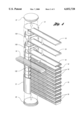
- FIG. 5 is a partially exploded view of a heat exchanger using a third embodiment of the manifold inserts
- FIG. 6 is a cross-sectional end view of the heat exchanger shown in FIG. 5;
- FIG. 7 is a partial cross-sectional side view of the heat exchanger shown in FIG. 5;
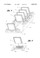
- FIG. 8 is a partial exploded view of a heat exchanger using a fourth embodiment of the manifold insert
- FIG. 9 is a perspective of a fifth embodiment of the manifold insert.
- FIG. 10 is a partial exploded view of a heat exchanger incorporating the manifold insert shown in FIG. 9;
- FIG. 11 is a perspective of a manifold insert for multiple rows of tubes.
- FIG. 12 is a perspective of a manifold insert for staggered rows of tubes.
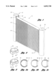
- FIG. 1 shows a partially completed assembly of an adjustable pitch heat exchanger 10 of the type disclosed by this invention.
- the heat exchanger 10 has a pair of spatially separated manifolds or headers 12 and 14 interconnected by a plurality of fluid transverse tubes 16.
- the fluid transfer tubes are attached to the manifolds 12 and 14 by manifold inserts 20 as shall be described hereinafter.
- Corrugated fins 18 are inserted between and fused to the fluid transverse tubes 16 to enhance the heat exchange between a fluid flowing in the tubes 16 and an external atmosphere such as air.
- the manifolds 12 and 14, the tubes 16, fins 18 and inserts 20 are fused to each other to form an integral fluid-tight assembly.
- a heat exchanger 10 embodying the assembly shown in FIG. 1 may be used as a radiator, oil cooler, charge air cooler, condenser, evaporator, or any other type of heat exchange application.
- each manifold insert 20 is a cylindrical element 22 having contoured recesses 24 and 26 provided at opposite end faces thereof. These recesses 24 and 26 are contoured to mate with the external contour of the tubes 16.
- the tubes 16 have an oblong cross-section, however, the tubes may have a circular cross-section or any other shape known in the art.
- the recesses 24 and 26 may be machined, stamped, coined, or made by any other method known in the art.
- the length or height of each insert element 22 is selectable to adjust the pitch or spacing between the adjacent tubes 16 as desired.
- the manifolds 12 and 14 are made from an elongated hollow member such as cylindrical tubes 28 having longitudinal slots 30 provided along the length thereof as shown in FIG. 1.
- the elongated hollow member 28 may have a square, hexagonal or oval cross-section.
- the inserts 20 are slidably received in the tubes 28.
- the width of the longitudinal slots 30 is selected to be greater than the width of the tubes 16.
- the tubes 16, manifolds 12 and 14, manifold inserts 20 and fins 18 are preferably made from an aluminum alloy clad with a solder or brazing material commercially available as "ALCAN” or "ALUMAX".
- the thickness of the cladding material is approximately 5 to 10% of the total thickness of the material being used and has a melting temperature significantly less than aluminum alloy.
- the manifold inserts 20 are received into each manifold 12 and 14 in an alternating arrangement with the tubes 16 until the desired number of tubes are inserted.
- the recesses 24 are omitted on the external faces of the end inserts 20 to provide a flat sealing surface.
- End caps 32 may be attached to the opposite ends of each manifold as shown in FIG. 4 to complete the assembly of the heat exchanger 10.
- Inlet and outlet connectors (not shown) may be added to the manifolds 12 and 14 as is known in the art.
- the primary advantages of the heat exchanger as described above is that it permits a rapid and inexpensive fabrication of low production or prototype heat exchanger cores 10. It permits the use of a different number of tubes and different spacings or pitch between the tubes without the need to use expensive dies and complex labor-intensive assembly.
- FIG. 3 An alternate embodiment 120 of the manifold insert 20 is shown in FIG. 3.
- the insert 120 is a "C" shaped element 122 having a selectable length.
- the recesses 24 and 26 are provided on the opposite faces of the "C” shaped element 122 opposite the open portion of the "C” as shown.
- the external diameter of the insert 120 is selected to be an interference fit into the manifolds 12 and 14.
- the "C" shaped configuration of the insert 120 permits it to be elastically compressed, eliminating a binding condition as it is inserted into the manifolds 12 and 14.
- the angular or arcuate width of the opening portion of the "C” shaped element may be any angle less than 160°, as shown in FIG. 3c, so that it will be self-centering within the manifold.
- FIG. 3b shows the open portion of the "C" shaped segment and the location of the recess 24 relative to the slot 30, being intermediate the positions shown in FIGS. 3a and 3c.
- FIG. 4 shows the assembly procedure of a heat exchanger 10 according to the invention using inserts 120. Again, the inserts 120 and the tubes 16 are received in the manifolds 12 and 14 in an alternating sequence. The assembly is completed by inserting corrugated fins 18 between adjacent tubes 16 and the placing of end caps 32 at the opposite ends of the manifolds 12 and 14.
- each insert 220 consists of a rectangular "U" shaped plate 222 having a punched or coined aperture 224 sized to receive the ends of the tubes 16 with an interference fit.
- the manifolds 12 and 14 consist of a "U" shaped member 226 having inwardly-facing rectangular channels 228 provided at the terminal ends at the ends of the legs 230 of the "U" shaped member 226.
- the inserts 220 are slidably received in the rectangular channels 228 as shown.
- the inserts are slidably received into the rectangular channels 228 and the tubes 16 are pressed into the apertures 224.
- the assembled heat exchanger is heated to fuse or braze the entire assembly as an integral fluid tight assembly.
- FIG. 8 A still alternate embodiment 320 of the insert 20 compatible with the "U" shaped manifold 226 is shown on FIG. 8.
- the inserts 320 have the ends closed to form an open faced rectangular box 322 having a tube aperture provided therethrough.
- the assembly of the heat exchanger is fabricated in the same manner as the heat exchanger embodiment shown on FIG. 5.
- FIGS. 9-10 Another embodiment 420 of the insert 20 is shown in FIGS. 9-10.
- the insert consists of stepped plate having a rectangular upper portion 422 and a contiguous rectangular lower portion 424.
- the upper portion 422 has a centrally provided tube aperture 426 sized to receive an end of the tube 16 with an interference fit.
- the lower portion 224 has a tube clearance recess 428 provided therein.
- the inserts 420 are inserted into the rectangular channels 432 provided at the open end of the manifold 430.
- the manifold 430 is comparable to the manifold discussed relative to FIGS. 5 and 6 having rectangular channels 228 provided at the terminal ends of the legs 230 of a "U" shaped member 226.
- the upper portions 422 of the inserts 420 overlap the lower portions 424 of an adjacent insert 420 as shown in FIG. 10.
- This embodiment of the insert 420 is suitably adapted for heat exchangers having substantial internal to external pressure differences because it provides increased sealing areas between adjacent inserts and the manifolds.
- each insert such as insert 520, may have two or more offset apertures 522 receiving at least a second row of tubes 16. These additional rows of tubes may be in line with each other as shown on FIG. 11 or may be staggered as shown in FIG. 12.
- the offset tube apertures 622 of the insert 620 are staggered relative to each other so that the tubes in the second or subsequent rows lie in between the tubes in the preceding row of tubes.
Landscapes
- Engineering & Computer Science (AREA)
- Physics & Mathematics (AREA)
- Thermal Sciences (AREA)
- Mechanical Engineering (AREA)
- General Engineering & Computer Science (AREA)
- Geometry (AREA)
- Heat-Exchange Devices With Radiators And Conduit Assemblies (AREA)
Abstract
Description
Claims (12)
Priority Applications (1)
| Application Number | Priority Date | Filing Date | Title |
|---|---|---|---|
| US09/190,327 US6032728A (en) | 1998-11-12 | 1998-11-12 | Variable pitch heat exchanger |
Applications Claiming Priority (1)
| Application Number | Priority Date | Filing Date | Title |
|---|---|---|---|
| US09/190,327 US6032728A (en) | 1998-11-12 | 1998-11-12 | Variable pitch heat exchanger |
Publications (1)
| Publication Number | Publication Date |
|---|---|
| US6032728A true US6032728A (en) | 2000-03-07 |
Family
ID=22700884
Family Applications (1)
| Application Number | Title | Priority Date | Filing Date |
|---|---|---|---|
| US09/190,327 Expired - Fee Related US6032728A (en) | 1998-11-12 | 1998-11-12 | Variable pitch heat exchanger |
Country Status (1)
| Country | Link |
|---|---|
| US (1) | US6032728A (en) |
Cited By (35)
| Publication number | Priority date | Publication date | Assignee | Title |
|---|---|---|---|---|
| US6119340A (en) * | 1998-11-16 | 2000-09-19 | Norsk Hydro A.S. | Heat exchanger member and baffle installation method therefor |
| US6505481B2 (en) * | 2000-12-23 | 2003-01-14 | Behr Gmbh & Co. | Refrigerant condenser |
| US20030121649A1 (en) * | 2001-12-27 | 2003-07-03 | Seiler Thomas F. | Heat exchanger with internal slotted manifold |
| US20030192682A1 (en) * | 2000-06-23 | 2003-10-16 | Andrew Lowenstein | Heat exchange assembly |
| GB2390148A (en) * | 2002-06-25 | 2003-12-31 | Visteon Global Tech Inc | A variable volume condenser assembly |
| US6702190B1 (en) | 2001-07-02 | 2004-03-09 | Arvin Technologies, Inc. | Heat transfer system for a vehicle |
| WO2004023056A1 (en) * | 2002-08-13 | 2004-03-18 | Behr Gmbh & Co. | Heat exchanger |
| FR2852383A1 (en) * | 2003-03-11 | 2004-09-17 | Valeo Thermique Moteur Sa | Collecting box for heat exchanger, has pipes constituted by superposition in alternation of spacer walls and cap walls that have cutout passages superimposing on cutout passages of spacer walls |
| US20040200605A1 (en) * | 2003-04-08 | 2004-10-14 | Honda Motor Co., Ltd. | Heat exchanger and evaporator |
| FR2871560A1 (en) | 2004-06-10 | 2005-12-16 | Valeo Climatisation Sa | Heat exchanger for use in motor vehicle, has collector including parts presenting sectional edges that are arranged so that open splits delimit opening for receiving end of tube to allow introduction ends of tube in collector |
| EP1770346A1 (en) * | 2005-09-30 | 2007-04-04 | Valeo Systemes Thermiques | Heat exchanger with alternated flat tubes |
| US20070261836A1 (en) * | 2004-06-15 | 2007-11-15 | Behr Gmbh & Co.. Kg | Heat Exchanger with an All-Metal Construction, in Particular an All-Aluminium Construction |
| EP1870658A1 (en) | 2006-06-20 | 2007-12-26 | Delphi Technologies, Inc. | A heat exchanger and a method of manufacturing thereof |
| US7337833B2 (en) * | 2001-12-28 | 2008-03-04 | Valeo Thermique Moteur S.A.S. | Circuit element for heat exchanger, in particular for motor vehicle, and resulting heat exchanger |
| US20080141686A1 (en) * | 2006-11-22 | 2008-06-19 | Johnson Controls Technology Company | Multichannel Evaporator With Flow Mixing Multichannel Tubes |
| US20080185123A1 (en) * | 2005-01-06 | 2008-08-07 | Wayne Nelson | Modular Heat Exchanger |
| US20090166020A1 (en) * | 2004-07-28 | 2009-07-02 | Smith Paul R | Automotive heat exchanger assemblies having internal fins and methods of making the same |
| US20090296345A1 (en) * | 2008-05-31 | 2009-12-03 | The Boeing Company | Thermal management device and method for making the same |
| US20100037652A1 (en) * | 2006-10-13 | 2010-02-18 | Carrier Corporation | Multi-channel heat exchanger with multi-stage expansion |
| DE102009035251A1 (en) * | 2009-07-29 | 2011-03-17 | Behr Industry Gmbh & Co. Kg | heat exchangers |
| US20110168367A1 (en) * | 2008-10-03 | 2011-07-14 | Honda Motor Co., Ltd. | Heat Exchanger With Recessed Fins |
| US20120048510A1 (en) * | 2010-08-25 | 2012-03-01 | Gea Wtt Gmbh | Plate heat exchanger in a sealed design |
| US8534346B1 (en) | 2006-11-16 | 2013-09-17 | Climatecraft Technologies, Inc. | Flexible heat exchanger |
| US20140090823A1 (en) * | 2012-09-28 | 2014-04-03 | Behr Gmbh & Co. Kg | Heat exchanger |
| US20150377560A1 (en) * | 2014-06-26 | 2015-12-31 | Valeo Autosystemy Sp. Z O.O. | Manifold, in particular for use in a cooler of a cooling system |
| US10208879B2 (en) * | 2016-05-31 | 2019-02-19 | A. Raymond Et Cie | Fluid connector assembly |
| US10408543B2 (en) * | 2015-05-01 | 2019-09-10 | Modine Manufacturing Company | Liquid to refrigerant heat exchanger, and method of operating the same |
| DE10306786B4 (en) * | 2002-02-19 | 2019-10-31 | Denso Corporation | heat exchangers |
| US11047266B2 (en) | 2019-10-30 | 2021-06-29 | General Electric Company | Heat exchanger with heat exchange tubes moveable between aligned and non-aligned positions |
| EP3985341A1 (en) * | 2020-10-16 | 2022-04-20 | LG Electronics Inc. | Heat exchanger and heat exchanger manufacturing method |
| US11357139B2 (en) * | 2019-04-24 | 2022-06-07 | Hyundai Motor Corporation | Cooling system for power conversion device |
| US20220333877A1 (en) * | 2019-09-27 | 2022-10-20 | Zhejiang Dunan Artificial Environment Co., Ltd. | Heat Exchanger |
| US20220333818A1 (en) * | 2021-04-15 | 2022-10-20 | Mahle International Gmbh | Heat exchanger with thick-film resistor |
| US20240159468A1 (en) * | 2020-12-30 | 2024-05-16 | Danfoss A/S | Heat exchanger |
| JP2024132908A (en) * | 2023-03-15 | 2024-10-01 | 三菱電機株式会社 | Heat exchanger and air conditioner equipped with same |
Citations (10)
| Publication number | Priority date | Publication date | Assignee | Title |
|---|---|---|---|---|
| US1993390A (en) * | 1932-03-22 | 1935-03-05 | Voss Johann Heinrich Hermann | Condenser for refrigerating systems |
| US2573161A (en) * | 1947-12-12 | 1951-10-30 | Trane Co | Heat exchanger |
| US2899177A (en) * | 1959-08-11 | Method of making same | ||
| DE7229162U (en) * | 1973-10-04 | Kuehlerfabrik Laengerer & Reich | Heat exchangers, in particular coolers for an internal combustion engine | |
| US4470452A (en) * | 1982-05-19 | 1984-09-11 | Ford Motor Company | Turbulator radiator tube and radiator construction derived therefrom |
| US4615385A (en) * | 1985-04-12 | 1986-10-07 | Modine Manufacturing Inc. | Heat exchanger |
| US4825941A (en) * | 1986-07-29 | 1989-05-02 | Showa Aluminum Kabushiki Kaisha | Condenser for use in a car cooling system |
| US4960169A (en) * | 1989-06-20 | 1990-10-02 | Modien Manufacturing Co. | Baffle for tubular heat exchanger header |
| US5052478A (en) * | 1989-05-19 | 1991-10-01 | Yuugen Kaisha Marunaka Seisakusho | Pipe for coolant condenser |
| US5193613A (en) * | 1992-06-30 | 1993-03-16 | Wallis Bernard J | Heat exchanger header tube and method of making |
-
1998
- 1998-11-12 US US09/190,327 patent/US6032728A/en not_active Expired - Fee Related
Patent Citations (12)
| Publication number | Priority date | Publication date | Assignee | Title |
|---|---|---|---|---|
| US2899177A (en) * | 1959-08-11 | Method of making same | ||
| DE7229162U (en) * | 1973-10-04 | Kuehlerfabrik Laengerer & Reich | Heat exchangers, in particular coolers for an internal combustion engine | |
| US1993390A (en) * | 1932-03-22 | 1935-03-05 | Voss Johann Heinrich Hermann | Condenser for refrigerating systems |
| US2573161A (en) * | 1947-12-12 | 1951-10-30 | Trane Co | Heat exchanger |
| US4470452A (en) * | 1982-05-19 | 1984-09-11 | Ford Motor Company | Turbulator radiator tube and radiator construction derived therefrom |
| US4615385A (en) * | 1985-04-12 | 1986-10-07 | Modine Manufacturing Inc. | Heat exchanger |
| US4615385B1 (en) * | 1985-04-12 | 1994-12-20 | Modine Mfg Co | Heat exchanger |
| US4825941A (en) * | 1986-07-29 | 1989-05-02 | Showa Aluminum Kabushiki Kaisha | Condenser for use in a car cooling system |
| US4825941B1 (en) * | 1986-07-29 | 1997-07-01 | Showa Aluminum Corp | Condenser for use in a car cooling system |
| US5052478A (en) * | 1989-05-19 | 1991-10-01 | Yuugen Kaisha Marunaka Seisakusho | Pipe for coolant condenser |
| US4960169A (en) * | 1989-06-20 | 1990-10-02 | Modien Manufacturing Co. | Baffle for tubular heat exchanger header |
| US5193613A (en) * | 1992-06-30 | 1993-03-16 | Wallis Bernard J | Heat exchanger header tube and method of making |
Cited By (47)
| Publication number | Priority date | Publication date | Assignee | Title |
|---|---|---|---|---|
| US6119340A (en) * | 1998-11-16 | 2000-09-19 | Norsk Hydro A.S. | Heat exchanger member and baffle installation method therefor |
| US20030192682A1 (en) * | 2000-06-23 | 2003-10-16 | Andrew Lowenstein | Heat exchange assembly |
| US6745826B2 (en) * | 2000-06-23 | 2004-06-08 | Ail Research, Inc. | Heat exchange assembly |
| US6505481B2 (en) * | 2000-12-23 | 2003-01-14 | Behr Gmbh & Co. | Refrigerant condenser |
| US6702190B1 (en) | 2001-07-02 | 2004-03-09 | Arvin Technologies, Inc. | Heat transfer system for a vehicle |
| US20030121649A1 (en) * | 2001-12-27 | 2003-07-03 | Seiler Thomas F. | Heat exchanger with internal slotted manifold |
| US7337833B2 (en) * | 2001-12-28 | 2008-03-04 | Valeo Thermique Moteur S.A.S. | Circuit element for heat exchanger, in particular for motor vehicle, and resulting heat exchanger |
| DE10306786B4 (en) * | 2002-02-19 | 2019-10-31 | Denso Corporation | heat exchangers |
| GB2390148A (en) * | 2002-06-25 | 2003-12-31 | Visteon Global Tech Inc | A variable volume condenser assembly |
| US20050236149A1 (en) * | 2002-08-13 | 2005-10-27 | Behr Gmbh & Co. Kg | Heat exchanger |
| WO2004023056A1 (en) * | 2002-08-13 | 2004-03-18 | Behr Gmbh & Co. | Heat exchanger |
| FR2852383A1 (en) * | 2003-03-11 | 2004-09-17 | Valeo Thermique Moteur Sa | Collecting box for heat exchanger, has pipes constituted by superposition in alternation of spacer walls and cap walls that have cutout passages superimposing on cutout passages of spacer walls |
| US20040200605A1 (en) * | 2003-04-08 | 2004-10-14 | Honda Motor Co., Ltd. | Heat exchanger and evaporator |
| FR2871560A1 (en) | 2004-06-10 | 2005-12-16 | Valeo Climatisation Sa | Heat exchanger for use in motor vehicle, has collector including parts presenting sectional edges that are arranged so that open splits delimit opening for receiving end of tube to allow introduction ends of tube in collector |
| US20070261836A1 (en) * | 2004-06-15 | 2007-11-15 | Behr Gmbh & Co.. Kg | Heat Exchanger with an All-Metal Construction, in Particular an All-Aluminium Construction |
| US20090166020A1 (en) * | 2004-07-28 | 2009-07-02 | Smith Paul R | Automotive heat exchanger assemblies having internal fins and methods of making the same |
| US8387686B2 (en) * | 2004-07-28 | 2013-03-05 | Paul R. Smith | Automotive heat exchanger assemblies having internal fins and methods of making the same |
| US20080185123A1 (en) * | 2005-01-06 | 2008-08-07 | Wayne Nelson | Modular Heat Exchanger |
| US8607853B2 (en) * | 2005-01-06 | 2013-12-17 | Modular Heat Exchangers Limited | Modular heat exchanger connectable in multiple different configurations |
| FR2891615A1 (en) * | 2005-09-30 | 2007-04-06 | Valeo Systemes Thermiques | HEAT EXCHANGER WITH ALTERNATE FLAT TUBES. |
| EP1770346A1 (en) * | 2005-09-30 | 2007-04-04 | Valeo Systemes Thermiques | Heat exchanger with alternated flat tubes |
| EP1870658A1 (en) | 2006-06-20 | 2007-12-26 | Delphi Technologies, Inc. | A heat exchanger and a method of manufacturing thereof |
| US20100037652A1 (en) * | 2006-10-13 | 2010-02-18 | Carrier Corporation | Multi-channel heat exchanger with multi-stage expansion |
| US8534346B1 (en) | 2006-11-16 | 2013-09-17 | Climatecraft Technologies, Inc. | Flexible heat exchanger |
| US7802439B2 (en) * | 2006-11-22 | 2010-09-28 | Johnson Controls Technology Company | Multichannel evaporator with flow mixing multichannel tubes |
| US20080141686A1 (en) * | 2006-11-22 | 2008-06-19 | Johnson Controls Technology Company | Multichannel Evaporator With Flow Mixing Multichannel Tubes |
| US20090296345A1 (en) * | 2008-05-31 | 2009-12-03 | The Boeing Company | Thermal management device and method for making the same |
| US8146651B2 (en) | 2008-10-03 | 2012-04-03 | Honda Motor Co., Ltd. | Heat exchanger with recessed fins |
| US20110168367A1 (en) * | 2008-10-03 | 2011-07-14 | Honda Motor Co., Ltd. | Heat Exchanger With Recessed Fins |
| WO2011012684A3 (en) * | 2009-07-29 | 2011-05-19 | Behr Industry Gmbh & Co. Kg | Heat exchanger |
| DE102009035251A1 (en) * | 2009-07-29 | 2011-03-17 | Behr Industry Gmbh & Co. Kg | heat exchangers |
| US20120048510A1 (en) * | 2010-08-25 | 2012-03-01 | Gea Wtt Gmbh | Plate heat exchanger in a sealed design |
| US9746246B2 (en) * | 2010-08-25 | 2017-08-29 | Gea Wtt Gmbh | Plate heat exchanger in a sealed design |
| US20140090823A1 (en) * | 2012-09-28 | 2014-04-03 | Behr Gmbh & Co. Kg | Heat exchanger |
| US9593891B2 (en) * | 2012-09-28 | 2017-03-14 | Mahle International Gmbh | Heat exchanger |
| US20150377560A1 (en) * | 2014-06-26 | 2015-12-31 | Valeo Autosystemy Sp. Z O.O. | Manifold, in particular for use in a cooler of a cooling system |
| US10408543B2 (en) * | 2015-05-01 | 2019-09-10 | Modine Manufacturing Company | Liquid to refrigerant heat exchanger, and method of operating the same |
| US10208879B2 (en) * | 2016-05-31 | 2019-02-19 | A. Raymond Et Cie | Fluid connector assembly |
| US11357139B2 (en) * | 2019-04-24 | 2022-06-07 | Hyundai Motor Corporation | Cooling system for power conversion device |
| US20220333877A1 (en) * | 2019-09-27 | 2022-10-20 | Zhejiang Dunan Artificial Environment Co., Ltd. | Heat Exchanger |
| US12130100B2 (en) * | 2019-09-27 | 2024-10-29 | Zhejiang Dunan Artificial Environment Co., Ltd. | Heat exchanger |
| US11047266B2 (en) | 2019-10-30 | 2021-06-29 | General Electric Company | Heat exchanger with heat exchange tubes moveable between aligned and non-aligned positions |
| EP3985341A1 (en) * | 2020-10-16 | 2022-04-20 | LG Electronics Inc. | Heat exchanger and heat exchanger manufacturing method |
| US11940219B2 (en) | 2020-10-16 | 2024-03-26 | Lg Electronics Inc. | Heat exchanger and heat exchanger manufacturing method |
| US20240159468A1 (en) * | 2020-12-30 | 2024-05-16 | Danfoss A/S | Heat exchanger |
| US20220333818A1 (en) * | 2021-04-15 | 2022-10-20 | Mahle International Gmbh | Heat exchanger with thick-film resistor |
| JP2024132908A (en) * | 2023-03-15 | 2024-10-01 | 三菱電機株式会社 | Heat exchanger and air conditioner equipped with same |
Similar Documents
| Publication | Publication Date | Title |
|---|---|---|
| US6032728A (en) | Variable pitch heat exchanger | |
| US4778004A (en) | Heat exchanger assembly with integral fin unit | |
| US10845126B2 (en) | Counterflow helical heat exchanger | |
| US5036911A (en) | Embossed plate oil cooler | |
| US5372188A (en) | Heat exchanger for a refrigerant system | |
| EP0360362B1 (en) | Condenser | |
| US5799727A (en) | Refrigerant tubes for heat exchangers | |
| US5219024A (en) | Heat exchanger having a bundle of tubes, in particular for a motor vehicle | |
| US5094293A (en) | Heat exchanger | |
| US5209292A (en) | Condenser header and tank assembly with interference fit baffle | |
| US7708054B2 (en) | Heat exchanger | |
| US5052480A (en) | Pipe for coolant condenser | |
| US9901966B2 (en) | Method for fabricating flattened tube finned heat exchanger | |
| US9593889B2 (en) | Heat exchanger construction | |
| JP2004225961A (en) | Multi-flow heat exchanger | |
| JP3141044B2 (en) | Heat exchanger with small core depth | |
| US20030131979A1 (en) | Oil cooler | |
| US5890288A (en) | Method for making a heat exchanger tube | |
| US5318111A (en) | Integral baffle assembly for parallel flow heat exchanger | |
| CA1313182C (en) | In tank oil cooler | |
| US6364006B1 (en) | Beaded plate for a heat exchanger and method of making same | |
| US4881311A (en) | Heat exchanger assembly with integral fin unit | |
| US5934365A (en) | Heat exchanger | |
| EP1067350B1 (en) | Beaded plate for a heat exchanger and method of making same | |
| EP0769669A1 (en) | Heat exchanger |
Legal Events
| Date | Code | Title | Description |
|---|---|---|---|
| AS | Assignment |
Owner name: LIVERNOIS RESEARCH & DEVELOPMENT CO., MICHIGAN Free format text: ASSIGNMENT OF ASSIGNORS INTEREST;ASSIGNORS:ROSS, GARY R.;BACOCCINI, JAMES R.;REEL/FRAME:009592/0298 Effective date: 19981102 |
|
| AS | Assignment |
Owner name: HEATCRAFT INC., TEXAS Free format text: ASSIGNMENT OF ASSIGNORS INTEREST;ASSIGNOR:LIVERNOIS RESEARCH & DEVELOPMENT CO.;REEL/FRAME:012795/0183 Effective date: 20020307 |
|
| AS | Assignment |
Owner name: LIVERNOIS ENGINEERING CO., MICHIGAN Free format text: ASSIGNMENT OF ASSIGNORS INTEREST;ASSIGNOR:HEATCRAFT INC.;REEL/FRAME:013158/0865 Effective date: 20020617 |
|
| FPAY | Fee payment |
Year of fee payment: 4 |
|
| REMI | Maintenance fee reminder mailed | ||
| LAPS | Lapse for failure to pay maintenance fees | ||
| STCH | Information on status: patent discontinuation |
Free format text: PATENT EXPIRED DUE TO NONPAYMENT OF MAINTENANCE FEES UNDER 37 CFR 1.362 |
|
| FP | Lapsed due to failure to pay maintenance fee |
Effective date: 20080307 |