US6032301A - Plunger - Google Patents
Plunger Download PDFInfo
- Publication number
- US6032301A US6032301A US09/243,427 US24342799A US6032301A US 6032301 A US6032301 A US 6032301A US 24342799 A US24342799 A US 24342799A US 6032301 A US6032301 A US 6032301A
- Authority
- US
- United States
- Prior art keywords
- correlative
- handle
- shaft
- connecting rod
- stopper
- Prior art date
- Legal status (The legal status is an assumption and is not a legal conclusion. Google has not performed a legal analysis and makes no representation as to the accuracy of the status listed.)
- Expired - Fee Related
Links
Images


Classifications
-
- B—PERFORMING OPERATIONS; TRANSPORTING
- B08—CLEANING
- B08B—CLEANING IN GENERAL; PREVENTION OF FOULING IN GENERAL
- B08B9/00—Cleaning hollow articles by methods or apparatus specially adapted thereto
- B08B9/02—Cleaning pipes or tubes or systems of pipes or tubes
- B08B9/027—Cleaning the internal surfaces; Removal of blockages
- B08B9/032—Cleaning the internal surfaces; Removal of blockages by the mechanical action of a moving fluid, e.g. by flushing
- B08B9/0321—Cleaning the internal surfaces; Removal of blockages by the mechanical action of a moving fluid, e.g. by flushing using pressurised, pulsating or purging fluid
-
- E—FIXED CONSTRUCTIONS
- E03—WATER SUPPLY; SEWERAGE
- E03C—DOMESTIC PLUMBING INSTALLATIONS FOR FRESH WATER OR WASTE WATER; SINKS
- E03C1/00—Domestic plumbing installations for fresh water or waste water; Sinks
- E03C1/12—Plumbing installations for waste water; Basins or fountains connected thereto; Sinks
- E03C1/30—Devices to facilitate removing of obstructions in waste-pipes or sinks
Definitions
- This invention relates to a plunger, particularly to one provided with an air pressure ball for storing air to be forcefully flowed into a clogged pipe or drain for clearing the clog.
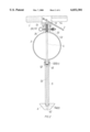
- a known conventional plunger shown in FIG. 6, includes a sucking cup 10 made of rubber connected with a long handle 20.
- the sucking cup 10 is placed on a mouth of a clogged pipe or drain of a toilet bowl as shown in FIG. 7, and is compressed and released alternately again and again so as to let it produce sucking force to turn over a clog and clear the passageway of the pipe or drain.
- this conventional has its sucking force quite limited, necessary to operate it laboriously to clear a clog and sometime cannot clear it due to small sucking force of the sucking cup 10, having not much practicability.
- the main object of the invention is to offer a plunger having a pressure ball under an upper base, a correlative tubular shaft extending vertically through the pressure ball and having its upper end combined with a handle pivotally connected with the upper base and its lower end connected with a connecting rod, and a lower end stopper threadably connected to the lower end of the connecting rod. Then air may be stored in the pressure ball by means of an air pump or compressor, and the handle is operated to pull up the correlative tubular shaft to let its lower end separate from the connecting rod so that the air stored in the pressure ball may forcefully flow out of the lower end stopper into clogged pipe for clearing the clog with a powerful force.
- FIG. 1 is an exploded perspective view of a plunger of the present invention.
- FIG. 2 is cross-sectional view of the plunger of the present invention.
- FIG. 3 is a partial enlarged cross-sectional view of the plunger of the present invention.
- FIG. 4 is a cross-sectional view of the plunger of the present invention, showing it being operated.
- FIG. 5 is a partial perspective view of a second preferred embodiment of a plunger of the present invention.
- FIG. 6 is a perspective view of a known conventional plunger.
- FIG. 7 is a cross-sectional view of the known conventional plunger, showing it operating practically.
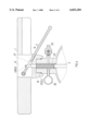
- a first preferred embodiment of a plunger of the invention includes an upper base 1, a long handle 2, a pressure ball 3, a correlative tubular shaft 4, a connecting rod 5, and a lower end stopper 6 as main components combined together.
- the upper base 1 has a hollow chamber 11 formed in an intermediate portion with an upper open side, a threaded hole 12 formed in a projecting lower portion, a hole communicating the chamber 11 with the threaded hole 12 in the projecting lower portion, and an opening 14 formed at a right lower side of the chamber 11.
- the long handle 2 is pivotally connected in the hollow chamber 11 and located under the upper base 1, having a rear end protruding out of the opening 14 and a slot 21 formed in a front end.
- the pressure ball 3 is to store air therein, having male threads 31 and 32 respectively in an upper and a lower end.
- the upper male threads 31 engage tightly with the threaded hole 12 of the upper base 1.
- the pressure ball 3 further has an air inlet 33 laterally provided at a right side of an upper block formed integrally with the pressure ball 3, and a pressure gauge 34 fixed at a left side of the upper block.
- the correlative tubular shaft 4 has a hole 41 in an upper end for a pin 42 to pass laterally through and rest on two sides of the slot 21 of the handle 2 after the shaft 4 protrudes up through the slot 21, as shown in FIG. 3. Further, a coil spring 43 is fitted around an upper portion of the correlative shaft 4.
- the shaft 4 is further provided with male threads 44 formed in a lower end.
- a cone-shaped stopper 45 is provided to have female threads 451 for male threads 44 of the shaft 4 to engage tightly after the shaft 4 extends vertically down through the pressure ball 3.
- the connecting rod 5 has female threads 51 formed in an upper end to engage the male threads 32 of the pressure ball 3.
- the lower end stopper 6 is cone-shaped, having female threads 61 in an upper end to engage the male threads 54 of the connecting rod 5.
- the handle 2 is pivotally combined with the upper base 1, and then the coil spring 43 is fitted around the correlative shaft 4, which is then inserted up through the slot 21 of the handle 2, with the pin 42 made to pass through the hole 41, combining the correlative shaft 4 with the handle 2.
- the lower end of the correlative shaft 4 is inserted vertically down in the pressure ball 3, with the male threads 44 protruding out of the pressure ball 3 and engaging with the female threads 451 of the upper end stopper 45, and with the male threads 31 engaging with the threaded hole 12 of the upper base 1.
- the male threads 32 of the pressure ball 3 is made to engage the female threads 51 of the connecting rod 5.
- the cone-shaped upper stopper 45 just fits in the cone-shaped hole 52 of the connecting rod 5, and the male threads 54 engage tightly with the female threads 61 of the lower end stopper 6. Then the plunger is finished in assemblage.
- the lower end stopper 6 is placed sealingly on the mouth of the clogged pipe or drain, and the air inlet 33 is connected to a compressor or an air pump. Then air is pumped through the air inlet 33 into the pressure ball 3, which then stores air therein. Meanwhile, the correlative shaft 4 is biased by the coil spring 43, with the upper stopper 45 forcefully pushing the cone-shaped hole 52 and hampering the air in the pressure ball 3 from flowing down.
- a second preferred embodiment of the plunger in the present invention has the same structure as the first preferred embodiment, except the correlative shaft 4, which has a threaded hole 46 formed in the upper end, as shown in FIG. 5, for a screw 47 with a ball-shaped head and threads 471 to engage with.
- the diameter of the ball-shaped head has a larger diameter than the width of the slot 21 so that the screw 47 may rest on the slot 21 after the upper end of the correlative shaft protrudes up through the slot 21, securing the correlative shaft 4 with the handle 2.
- the plunger in the invention utilizes air pressure obtained by an air pump or compressor to be stored in the pressure ball for clearing a clogged pipe or drain.
Abstract
A plunger includes an upper base, a pressure ball under the upper base, a correlative tubular shaft extending vertically through the pressure ball, a handle pivotally connected with an upper end of the correlative tubular shaft, a connecting rod connects to the correlative shaft, and a lower end stopper threadably connected with the lower end of the connecting rod. The pressure ball can store air supplied by an air pump or compressor through an air inlet. The handle can be operated to let the air stored in the pressure ball flow through the correlative shaft, the connecting rod and the lower end stopper into a clogged pipe or drain for clearing passage with a large force of pressured air.
Description
This invention relates to a plunger, particularly to one provided with an air pressure ball for storing air to be forcefully flowed into a clogged pipe or drain for clearing the clog.
A known conventional plunger shown in FIG. 6, includes a sucking cup 10 made of rubber connected with a long handle 20. In using it, the sucking cup 10 is placed on a mouth of a clogged pipe or drain of a toilet bowl as shown in FIG. 7, and is compressed and released alternately again and again so as to let it produce sucking force to turn over a clog and clear the passageway of the pipe or drain. However, this conventional has its sucking force quite limited, necessary to operate it laboriously to clear a clog and sometime cannot clear it due to small sucking force of the sucking cup 10, having not much practicability.
The main object of the invention is to offer a plunger having a pressure ball under an upper base, a correlative tubular shaft extending vertically through the pressure ball and having its upper end combined with a handle pivotally connected with the upper base and its lower end connected with a connecting rod, and a lower end stopper threadably connected to the lower end of the connecting rod. Then air may be stored in the pressure ball by means of an air pump or compressor, and the handle is operated to pull up the correlative tubular shaft to let its lower end separate from the connecting rod so that the air stored in the pressure ball may forcefully flow out of the lower end stopper into clogged pipe for clearing the clog with a powerful force.
This invention will be better understood by reference to the accompanying drawings, wherein:
FIG. 1 is an exploded perspective view of a plunger of the present invention.
FIG. 2 is cross-sectional view of the plunger of the present invention.
FIG. 3 is a partial enlarged cross-sectional view of the plunger of the present invention.
FIG. 4 is a cross-sectional view of the plunger of the present invention, showing it being operated.
FIG. 5 is a partial perspective view of a second preferred embodiment of a plunger of the present invention.
FIG. 6 is a perspective view of a known conventional plunger.
FIG. 7 is a cross-sectional view of the known conventional plunger, showing it operating practically.
A first preferred embodiment of a plunger of the invention, as shown in FIGS. 1 and 2, includes an upper base 1, a long handle 2, a pressure ball 3, a correlative tubular shaft 4, a connecting rod 5, and a lower end stopper 6 as main components combined together.
The upper base 1 has a hollow chamber 11 formed in an intermediate portion with an upper open side, a threaded hole 12 formed in a projecting lower portion, a hole communicating the chamber 11 with the threaded hole 12 in the projecting lower portion, and an opening 14 formed at a right lower side of the chamber 11.
The long handle 2 is pivotally connected in the hollow chamber 11 and located under the upper base 1, having a rear end protruding out of the opening 14 and a slot 21 formed in a front end.
The pressure ball 3 is to store air therein, having male threads 31 and 32 respectively in an upper and a lower end. The upper male threads 31 engage tightly with the threaded hole 12 of the upper base 1. The pressure ball 3 further has an air inlet 33 laterally provided at a right side of an upper block formed integrally with the pressure ball 3, and a pressure gauge 34 fixed at a left side of the upper block.
The correlative tubular shaft 4 has a hole 41 in an upper end for a pin 42 to pass laterally through and rest on two sides of the slot 21 of the handle 2 after the shaft 4 protrudes up through the slot 21, as shown in FIG. 3. Further, a coil spring 43 is fitted around an upper portion of the correlative shaft 4. The shaft 4 is further provided with male threads 44 formed in a lower end. A cone-shaped stopper 45 is provided to have female threads 451 for male threads 44 of the shaft 4 to engage tightly after the shaft 4 extends vertically down through the pressure ball 3.
The connecting rod 5 has female threads 51 formed in an upper end to engage the male threads 32 of the pressure ball 3. A short cone-shaped hole 52 formed under the female threads 51, a long passageway 53 formed under the cone-shaped hole 52, and male threads 54 in a lower end.
The lower end stopper 6 is cone-shaped, having female threads 61 in an upper end to engage the male threads 54 of the connecting rod 5. A center hole 62 under the female threads 61 communicating with the passageway 53 of the connecting rod 5 for air to flow through down.
In assembling, referring to FIGS. 2 and 3, firstly the handle 2 is pivotally combined with the upper base 1, and then the coil spring 43 is fitted around the correlative shaft 4, which is then inserted up through the slot 21 of the handle 2, with the pin 42 made to pass through the hole 41, combining the correlative shaft 4 with the handle 2. Next, the lower end of the correlative shaft 4 is inserted vertically down in the pressure ball 3, with the male threads 44 protruding out of the pressure ball 3 and engaging with the female threads 451 of the upper end stopper 45, and with the male threads 31 engaging with the threaded hole 12 of the upper base 1. After that, the male threads 32 of the pressure ball 3 is made to engage the female threads 51 of the connecting rod 5. Meanwhile, the cone-shaped upper stopper 45 just fits in the cone-shaped hole 52 of the connecting rod 5, and the male threads 54 engage tightly with the female threads 61 of the lower end stopper 6. Then the plunger is finished in assemblage.
In using, referring to FIG. 4, the lower end stopper 6 is placed sealingly on the mouth of the clogged pipe or drain, and the air inlet 33 is connected to a compressor or an air pump. Then air is pumped through the air inlet 33 into the pressure ball 3, which then stores air therein. Meanwhile, the correlative shaft 4 is biased by the coil spring 43, with the upper stopper 45 forcefully pushing the cone-shaped hole 52 and hampering the air in the pressure ball 3 from flowing down. When a user checks the pressure gauge 34 and knows the pressure valve reaches the necessary one, the user pulls up the handle 2, forcing the upper stopper 45 separate from the hole 52 to cause an aperture between the both, so that the air in the pressure ball 3 may flow through the passageway 53 of the connecting rod 5, the hole 62 of the lower end stopper 6, and then into the clogged pipe or drain. Thus, the clog may be forcefully moved to clear the passage of the pipe or drain.
A second preferred embodiment of the plunger in the present invention has the same structure as the first preferred embodiment, except the correlative shaft 4, which has a threaded hole 46 formed in the upper end, as shown in FIG. 5, for a screw 47 with a ball-shaped head and threads 471 to engage with. The diameter of the ball-shaped head has a larger diameter than the width of the slot 21 so that the screw 47 may rest on the slot 21 after the upper end of the correlative shaft protrudes up through the slot 21, securing the correlative shaft 4 with the handle 2.
In general, the plunger in the invention utilizes air pressure obtained by an air pump or compressor to be stored in the pressure ball for clearing a clogged pipe or drain.
Claims (2)
1. A plunger comprising:
an upper base having a chamber with an upper open side formed in an intermediate portion, a threaded hole formed under said chamber, a hole communicating said chamber and said threaded hole, and an opening formed in a right lower portion to said chamber;
a handle having a slot in a front portion;
a pressure ball having male threads respectively in an upper projecting portion and a lower projecting end, an air inlet communicating with said ball, and a pressure gauge communicating with said ball;
a correlative tubular shaft having a hole in an upper end thereof, a coil spring fitted around an upper portion of said shaft, and male threads formed in a lower end thereof and an upper cone-shaped stopper having female threads engaging said male threads of said lower end;
a connecting rod having a longitudinal passageway therethrough, female threads in an upper end thereof, a cone-shaped hole formed adjacent said female threads, and male threads formed in the lower end of said passageway;
a lower end stopper having a cone shape with a longitudinal passageway extending therethrough, female threads in an upper end thereof engaging said male threads of said passageway of said connecting rod;
said handle pivotally connected in said chamber of said upper base, having its rear end extending out of said opening of said upper base, said correlative tubular shaft having it upper end protruding up through said slot of said handle, means in said upper end of said correlative tubular shaft for engaging said slot of said handle to move said correlative shaft with said handle, said correlative shaft having it lower end inserted vertically down through said pressure ball and its male threads engaging with said female threads of said upper stopper, said male threads of said pressure ball engaging with said female threads of said upper base, said upper stopper fitting in said cone-shaped hole of said connecting rod, said male threads of said connecting rod engaging tightly with said female threads of said lower end stopper, said pressure ball adapted to store air therein supplied by an air pump or compressor, whereby air stored in said pressure ball can flow out of said lower end stopper into a clogged pipe or drain for clearing its passage if said handle is swung up to pull up said correlative shaft to let said upper stopper separate from said cone-shaped hole of said connecting rod.
2. The plunger as claimed in claim 1, wherein said means in said upper end of said correlative tubular shaft comprises female threads in said hole of said upper end of said shaft for receiving a ball-head screw to engage with said slot of said handle, wherein said ball-head of said screw has a larger diameter than the width of said slot to rest on said slot to engage said correlative shaft with said handle, or a pin fitted laterally in said upper end of said correlative tubular shaft for engaging said slot of said handle to move said correlative shaft with said handle.
Priority Applications (6)
| Application Number | Priority Date | Filing Date | Title |
|---|---|---|---|
| US09/243,427 US6032301A (en) | 1999-02-03 | 1999-02-03 | Plunger |
| GB9902969A GB2346662B (en) | 1999-02-03 | 1999-02-10 | Plunger |
| DE29902897U DE29902897U1 (en) | 1999-02-03 | 1999-02-18 | Pipe cleaning device |
| JP11046469A JP3017216B1 (en) | 1999-02-03 | 1999-02-24 | Pressure type vacuum cleaner |
| CA002290725A CA2290725A1 (en) | 1999-02-03 | 1999-11-26 | Plunger |
| FR9915487A FR2802226B3 (en) | 1999-02-03 | 1999-12-08 | PRESSURE CLEANER |
Applications Claiming Priority (6)
| Application Number | Priority Date | Filing Date | Title |
|---|---|---|---|
| US09/243,427 US6032301A (en) | 1999-02-03 | 1999-02-03 | Plunger |
| GB9902969A GB2346662B (en) | 1999-02-03 | 1999-02-10 | Plunger |
| DE29902897U DE29902897U1 (en) | 1999-02-03 | 1999-02-18 | Pipe cleaning device |
| JP11046469A JP3017216B1 (en) | 1999-02-03 | 1999-02-24 | Pressure type vacuum cleaner |
| CA002290725A CA2290725A1 (en) | 1999-02-03 | 1999-11-26 | Plunger |
| FR9915487A FR2802226B3 (en) | 1999-02-03 | 1999-12-08 | PRESSURE CLEANER |
Publications (1)
| Publication Number | Publication Date |
|---|---|
| US6032301A true US6032301A (en) | 2000-03-07 |
Family
ID=27543545
Family Applications (1)
| Application Number | Title | Priority Date | Filing Date |
|---|---|---|---|
| US09/243,427 Expired - Fee Related US6032301A (en) | 1999-02-03 | 1999-02-03 | Plunger |
Country Status (6)
| Country | Link |
|---|---|
| US (1) | US6032301A (en) |
| JP (1) | JP3017216B1 (en) |
| CA (1) | CA2290725A1 (en) |
| DE (1) | DE29902897U1 (en) |
| FR (1) | FR2802226B3 (en) |
| GB (1) | GB2346662B (en) |
Cited By (13)
| Publication number | Priority date | Publication date | Assignee | Title |
|---|---|---|---|---|
| US6519785B1 (en) | 2001-11-30 | 2003-02-18 | Piercy, Ii Jerry H. | Sanitary plunger device |
| US6550074B1 (en) | 2002-07-23 | 2003-04-22 | M. A. G. Engineering & Mfg. Co. | Air-burst drain plunger |
| US6892401B1 (en) | 2003-05-05 | 2005-05-17 | Thomas E. Mangum | Compressed air tool |
| US7062800B1 (en) | 2003-03-27 | 2006-06-20 | Benjamin Alfred | Plunger |
| US20060282941A1 (en) * | 2005-06-15 | 2006-12-21 | Long-Sheh Wang | High pressure plunger |
| US20110237402A1 (en) * | 2008-11-28 | 2011-09-29 | John Murray | Manual exercise device for toning and tightening flaccid tissue surrounding an airway |
| US20130000744A1 (en) * | 2011-06-30 | 2013-01-03 | Mark Slye | Mobile cleaning device and method of use |
| CN104389337A (en) * | 2014-11-29 | 2015-03-04 | 吕良 | Household dredging device |
| US20150074889A1 (en) * | 2013-09-17 | 2015-03-19 | Sean Donohue | Drain clearing device |
| CN109865722A (en) * | 2017-12-01 | 2019-06-11 | 上海宝钢工业技术服务有限公司 | Pipeline blockage-clearing device |
| US10350656B2 (en) | 2016-11-11 | 2019-07-16 | Milwaukee Electric Tool Corporation | Drain clearing air gun |
| US10683650B1 (en) * | 2019-02-22 | 2020-06-16 | Chintuo Industrial Co., Ltd. | Toilet plunger structure |
| CN114472792A (en) * | 2022-02-22 | 2022-05-13 | 徐州艾奇川自动化设备有限公司 | New energy automobile hub forging equipment and processing technology |
Families Citing this family (4)
| Publication number | Priority date | Publication date | Assignee | Title |
|---|---|---|---|---|
| DE102005016228B4 (en) * | 2005-04-07 | 2007-01-25 | Elias Lebessis | Pipe cleaner |
| CN106988392A (en) * | 2017-04-11 | 2017-07-28 | 中国华冶科工集团有限公司 | A kind of pipeline drainer and pipe-dredging method |
| CN108296232B (en) * | 2017-12-29 | 2018-11-20 | 广东骏驰科技股份有限公司 | A kind of device using high-pressure rotary airflow cleans automobile pipe-shaped parts |
| CN111151019B (en) * | 2020-01-09 | 2021-07-20 | 四川点石能源股份有限公司 | Evaporator circulating pipe anti-blocking system for MVR technology |
Citations (4)
| Publication number | Priority date | Publication date | Assignee | Title |
|---|---|---|---|---|
| US2059785A (en) * | 1935-04-29 | 1936-11-03 | Gaik Arnold | Air-pressure device |
| US2386870A (en) * | 1943-09-10 | 1945-10-16 | Lawton Jarvis Kenneth | Drain pipe cleaning gun |
| US3426774A (en) * | 1965-10-25 | 1969-02-11 | Surrey Steel Components Ltd | Hydraulic rams |
| GB2268994A (en) * | 1992-07-24 | 1994-01-26 | John Enver Emin | Gas-operated apparatus for unblocking pipes |
Family Cites Families (3)
| Publication number | Priority date | Publication date | Assignee | Title |
|---|---|---|---|---|
| US3315280A (en) * | 1964-12-21 | 1967-04-25 | Robert A Krenn | Drain opening device |
| GB1376127A (en) * | 1974-06-12 | 1974-12-04 | Winkelman F S | Devices for clearing blockages in pipes |
| US5522094A (en) * | 1994-01-10 | 1996-06-04 | Balazs; Louis F. | Water plunger for clearing clogged drains |
-
1999
- 1999-02-03 US US09/243,427 patent/US6032301A/en not_active Expired - Fee Related
- 1999-02-10 GB GB9902969A patent/GB2346662B/en not_active Expired - Fee Related
- 1999-02-18 DE DE29902897U patent/DE29902897U1/en not_active Expired - Lifetime
- 1999-02-24 JP JP11046469A patent/JP3017216B1/en not_active Expired - Lifetime
- 1999-11-26 CA CA002290725A patent/CA2290725A1/en not_active Abandoned
- 1999-12-08 FR FR9915487A patent/FR2802226B3/en not_active Expired - Fee Related
Patent Citations (4)
| Publication number | Priority date | Publication date | Assignee | Title |
|---|---|---|---|---|
| US2059785A (en) * | 1935-04-29 | 1936-11-03 | Gaik Arnold | Air-pressure device |
| US2386870A (en) * | 1943-09-10 | 1945-10-16 | Lawton Jarvis Kenneth | Drain pipe cleaning gun |
| US3426774A (en) * | 1965-10-25 | 1969-02-11 | Surrey Steel Components Ltd | Hydraulic rams |
| GB2268994A (en) * | 1992-07-24 | 1994-01-26 | John Enver Emin | Gas-operated apparatus for unblocking pipes |
Cited By (19)
| Publication number | Priority date | Publication date | Assignee | Title |
|---|---|---|---|---|
| US6519785B1 (en) | 2001-11-30 | 2003-02-18 | Piercy, Ii Jerry H. | Sanitary plunger device |
| US6550074B1 (en) | 2002-07-23 | 2003-04-22 | M. A. G. Engineering & Mfg. Co. | Air-burst drain plunger |
| US20040016048A1 (en) * | 2002-07-23 | 2004-01-29 | Allenbaugh Howard M. | Air-burst drain plunger |
| US6922854B2 (en) | 2002-07-23 | 2005-08-02 | The Howard And Veronica Allenbaugh Family Trust | Air-burst drain plunger |
| US7120943B2 (en) | 2002-07-23 | 2006-10-17 | M.A.G. Engineering & Mfg. Co. | Air-burst drain plunger |
| US7062800B1 (en) | 2003-03-27 | 2006-06-20 | Benjamin Alfred | Plunger |
| US6892401B1 (en) | 2003-05-05 | 2005-05-17 | Thomas E. Mangum | Compressed air tool |
| US7213273B2 (en) * | 2005-06-15 | 2007-05-08 | Chntuo Industrial Co., Ltd. | High pressure plunger |
| US20060282941A1 (en) * | 2005-06-15 | 2006-12-21 | Long-Sheh Wang | High pressure plunger |
| US20110237402A1 (en) * | 2008-11-28 | 2011-09-29 | John Murray | Manual exercise device for toning and tightening flaccid tissue surrounding an airway |
| US20130000744A1 (en) * | 2011-06-30 | 2013-01-03 | Mark Slye | Mobile cleaning device and method of use |
| US10487487B2 (en) * | 2011-06-30 | 2019-11-26 | Mark Slye | Mobile cleaning device and method of use |
| US20150074889A1 (en) * | 2013-09-17 | 2015-03-19 | Sean Donohue | Drain clearing device |
| CN104389337A (en) * | 2014-11-29 | 2015-03-04 | 吕良 | Household dredging device |
| US10350656B2 (en) | 2016-11-11 | 2019-07-16 | Milwaukee Electric Tool Corporation | Drain clearing air gun |
| US11235360B2 (en) | 2016-11-11 | 2022-02-01 | Milwaukee Electric Tool Corporation | Drain clearing air gun |
| CN109865722A (en) * | 2017-12-01 | 2019-06-11 | 上海宝钢工业技术服务有限公司 | Pipeline blockage-clearing device |
| US10683650B1 (en) * | 2019-02-22 | 2020-06-16 | Chintuo Industrial Co., Ltd. | Toilet plunger structure |
| CN114472792A (en) * | 2022-02-22 | 2022-05-13 | 徐州艾奇川自动化设备有限公司 | New energy automobile hub forging equipment and processing technology |
Also Published As
| Publication number | Publication date |
|---|---|
| FR2802226B3 (en) | 2001-11-02 |
| JP2000246201A (en) | 2000-09-12 |
| GB2346662B (en) | 2001-01-10 |
| GB9902969D0 (en) | 1999-03-31 |
| CA2290725A1 (en) | 2001-05-26 |
| GB2346662A (en) | 2000-08-16 |
| JP3017216B1 (en) | 2000-03-06 |
| FR2802226A3 (en) | 2001-06-15 |
| DE29902897U1 (en) | 1999-07-01 |
Similar Documents
| Publication | Publication Date | Title |
|---|---|---|
| US6032301A (en) | Plunger | |
| US8312570B1 (en) | Quick-installation structure of a toilet seat cover assembly | |
| US7648109B2 (en) | Sucker that is removed easily and quickly | |
| US7607382B2 (en) | Bicycle pump | |
| US7380731B1 (en) | Water sprayer having two water different spraying modes | |
| US7213273B2 (en) | High pressure plunger | |
| US8020588B2 (en) | Tire repair solution can | |
| US6676390B2 (en) | Manual air pump incorporating a foot switch in the base member | |
| US7287927B2 (en) | Valve assembly | |
| US7357154B1 (en) | Multi-stage positioning structure for a ceramic valve core | |
| US7383894B2 (en) | Pneumatic hammer drill (I) | |
| US6648615B2 (en) | Inflator | |
| US20030197069A1 (en) | Air-pressure sprayer structure | |
| US5823754A (en) | Manual pump | |
| US5699994A (en) | Sensor-type flush valve assembly with push button device for optional manual operation | |
| US20040115075A1 (en) | Miniature air compressor | |
| US6618872B1 (en) | Controlling device for a showerhead | |
| US6276405B1 (en) | Inflation nozzle provided with means to engage air valves of different types | |
| US5605253A (en) | Water-ejection toy | |
| US20060266848A1 (en) | Airbrush | |
| CN202274218U (en) | Gas-charging joint | |
| US6393626B1 (en) | Dual-acting plunger | |
| US6412669B1 (en) | Liquid sucking and dispensing device | |
| CN212261295U (en) | Water spraying structure of water spraying mop | |
| GB2445840A (en) | Suction cup having control handle and valve |
Legal Events
| Date | Code | Title | Description |
|---|---|---|---|
| AS | Assignment |
Owner name: CHNTUO INDUSTRIAL CO., LTD., TAIWAN Free format text: ASSIGNMENT OF ASSIGNORS INTEREST;ASSIGNOR:WANG, LONG-SHEH;REEL/FRAME:009770/0352 Effective date: 19990129 |
|
| REMI | Maintenance fee reminder mailed | ||
| LAPS | Lapse for failure to pay maintenance fees | ||
| FP | Expired due to failure to pay maintenance fee |
Effective date: 20040307 |
|
| STCH | Information on status: patent discontinuation |
Free format text: PATENT EXPIRED DUE TO NONPAYMENT OF MAINTENANCE FEES UNDER 37 CFR 1.362 |