US6028307A - Data acquisition and reduction method for multi-component flow - Google Patents
Data acquisition and reduction method for multi-component flow Download PDFInfo
- Publication number
- US6028307A US6028307A US08/939,247 US93924797A US6028307A US 6028307 A US6028307 A US 6028307A US 93924797 A US93924797 A US 93924797A US 6028307 A US6028307 A US 6028307A
- Authority
- US
- United States
- Prior art keywords
- holdup
- component
- fluid
- sub
- sbsb
- Prior art date
- Legal status (The legal status is an assumption and is not a legal conclusion. Google has not performed a legal analysis and makes no representation as to the accuracy of the status listed.)
- Expired - Lifetime
Links
- 238000000034 method Methods 0.000 title claims abstract description 40
- 230000009467 reduction Effects 0.000 title description 6
- 239000012530 fluid Substances 0.000 claims abstract description 107
- 239000000470 constituent Substances 0.000 claims abstract description 33
- 238000001514 detection method Methods 0.000 claims abstract description 10
- 238000006073 displacement reaction Methods 0.000 claims abstract description 4
- 238000004519 manufacturing process Methods 0.000 claims description 11
- 238000001739 density measurement Methods 0.000 claims description 8
- 238000005070 sampling Methods 0.000 claims description 8
- 230000005251 gamma ray Effects 0.000 claims description 5
- 238000012417 linear regression Methods 0.000 claims description 4
- 230000002452 interceptive effect Effects 0.000 claims description 3
- XLYOFNOQVPJJNP-UHFFFAOYSA-N water Substances O XLYOFNOQVPJJNP-UHFFFAOYSA-N 0.000 abstract description 41
- 150000002430 hydrocarbons Chemical class 0.000 abstract description 27
- 229930195733 hydrocarbon Natural products 0.000 abstract description 26
- 239000004215 Carbon black (E152) Substances 0.000 description 21
- 238000005259 measurement Methods 0.000 description 14
- 239000000203 mixture Substances 0.000 description 11
- 239000000523 sample Substances 0.000 description 7
- 230000004044 response Effects 0.000 description 5
- 230000000295 complement effect Effects 0.000 description 3
- 238000012937 correction Methods 0.000 description 3
- 239000011159 matrix material Substances 0.000 description 3
- 239000002245 particle Substances 0.000 description 3
- 230000002285 radioactive effect Effects 0.000 description 3
- 239000011435 rock Substances 0.000 description 3
- 238000013459 approach Methods 0.000 description 2
- 230000015572 biosynthetic process Effects 0.000 description 2
- 238000005755 formation reaction Methods 0.000 description 2
- 239000003595 mist Substances 0.000 description 2
- 238000012986 modification Methods 0.000 description 2
- 230000004048 modification Effects 0.000 description 2
- 230000002441 reversible effect Effects 0.000 description 2
- 238000012546 transfer Methods 0.000 description 2
- 230000000007 visual effect Effects 0.000 description 2
- 238000012935 Averaging Methods 0.000 description 1
- 230000008859 change Effects 0.000 description 1
- 238000010276 construction Methods 0.000 description 1
- 230000007812 deficiency Effects 0.000 description 1
- 230000002950 deficient Effects 0.000 description 1
- 230000000694 effects Effects 0.000 description 1
- 230000003993 interaction Effects 0.000 description 1
- 238000013507 mapping Methods 0.000 description 1
- 239000003209 petroleum derivative Substances 0.000 description 1
- 230000005855 radiation Effects 0.000 description 1
- 238000011946 reduction process Methods 0.000 description 1
- 238000011160 research Methods 0.000 description 1
- 230000001953 sensory effect Effects 0.000 description 1
- 238000010008 shearing Methods 0.000 description 1
- 238000013517 stratification Methods 0.000 description 1
- 230000001360 synchronised effect Effects 0.000 description 1
- 238000012360 testing method Methods 0.000 description 1
- 230000007704 transition Effects 0.000 description 1
Images


Classifications
-
- E—FIXED CONSTRUCTIONS
- E21—EARTH OR ROCK DRILLING; MINING
- E21B—EARTH OR ROCK DRILLING; OBTAINING OIL, GAS, WATER, SOLUBLE OR MELTABLE MATERIALS OR A SLURRY OF MINERALS FROM WELLS
- E21B47/00—Survey of boreholes or wells
- E21B47/10—Locating fluid leaks, intrusions or movements
-
- G—PHYSICS
- G01—MEASURING; TESTING
- G01N—INVESTIGATING OR ANALYSING MATERIALS BY DETERMINING THEIR CHEMICAL OR PHYSICAL PROPERTIES
- G01N33/00—Investigating or analysing materials by specific methods not covered by groups G01N1/00 - G01N31/00
- G01N33/26—Oils; Viscous liquids; Paints; Inks
- G01N33/28—Oils, i.e. hydrocarbon liquids
- G01N33/2823—Raw oil, drilling fluid or polyphasic mixtures
-
- E—FIXED CONSTRUCTIONS
- E21—EARTH OR ROCK DRILLING; MINING
- E21B—EARTH OR ROCK DRILLING; OBTAINING OIL, GAS, WATER, SOLUBLE OR MELTABLE MATERIALS OR A SLURRY OF MINERALS FROM WELLS
- E21B47/00—Survey of boreholes or wells
- E21B47/10—Locating fluid leaks, intrusions or movements
- E21B47/103—Locating fluid leaks, intrusions or movements using thermal measurements
-
- E—FIXED CONSTRUCTIONS
- E21—EARTH OR ROCK DRILLING; MINING
- E21B—EARTH OR ROCK DRILLING; OBTAINING OIL, GAS, WATER, SOLUBLE OR MELTABLE MATERIALS OR A SLURRY OF MINERALS FROM WELLS
- E21B47/00—Survey of boreholes or wells
- E21B47/10—Locating fluid leaks, intrusions or movements
- E21B47/107—Locating fluid leaks, intrusions or movements using acoustic means
-
- E—FIXED CONSTRUCTIONS
- E21—EARTH OR ROCK DRILLING; MINING
- E21B—EARTH OR ROCK DRILLING; OBTAINING OIL, GAS, WATER, SOLUBLE OR MELTABLE MATERIALS OR A SLURRY OF MINERALS FROM WELLS
- E21B47/00—Survey of boreholes or wells
- E21B47/10—Locating fluid leaks, intrusions or movements
- E21B47/11—Locating fluid leaks, intrusions or movements using tracers; using radioactivity
-
- E—FIXED CONSTRUCTIONS
- E21—EARTH OR ROCK DRILLING; MINING
- E21B—EARTH OR ROCK DRILLING; OBTAINING OIL, GAS, WATER, SOLUBLE OR MELTABLE MATERIALS OR A SLURRY OF MINERALS FROM WELLS
- E21B47/00—Survey of boreholes or wells
- E21B47/10—Locating fluid leaks, intrusions or movements
- E21B47/113—Locating fluid leaks, intrusions or movements using electrical indications; using light radiations
Definitions
- the present invention generally relates to oil and gas well (borehole) logging tools, and more particularly to an improved method of determining fluid holdup values by adjusting holdup measurements using complementary measurements which quantify smaller component (hydrocarbon) inclusions.
- the multiphase fluid is blended into a mixture and directed past a rotor assembly to measure the flow rate; gamma ray attenuation is also measured to determine average density, and this information is used along with derived data for densities of individual phases to determine volumetric fractions of the fluid phases as related to the total flow regime.
- Another problem occurs in that only the dielectric constant of the central portion of the well is measured. Very often flow will vary across a section of the well, especially in highly deviated or horizontal wells, where the fluid flow may become stratified across a cross-sectional area of the borehole. This flow pattern may result in prior art fluid holdup tools detecting only a small portion of the stratified flow, such as only in one phase, and not the other portions of the flow of produced fluids. Further, different flow patterns may be present both in vertical flow and horizontal flow. In horizontal flow, bubble flow and elongated bubble flow often will occur. Additionally, stratified flow, wave flow, slug flow, annular and annular mist flow, and dispersed froth flow may occur for horizontal flow depending upon different flow parameters and flow velocities.
- Vertical flow patterns may also include bubble flow, froth flow, annular and annular mist flow, and slug flow.
- different densities, frictional parameters, and different phases for different constituents of segregated multiphase fluid flow result in different flow rates for the different constituents.
- the gas phase may flow faster than the oil phase, which may flow faster than a water phase.
- one phase may flow in an opposite direction within the well to that of a new flow of fluids.
- the tool has rotating arms with flow sensors at the tips to measure flow at different localized regions, which allows detection of variations in fluid properties attributable to flow constituents. The result is more accurate determination of holdup values. See also U.S. Pat. No. 5,631,413 which discloses a similar holdup tool and flow meter.
- a method of determining a holdup value for a multiphase fluid generally comprising the steps of calculating a first holdup component using a first detection technique which is insensitive to small inclusions of a first fluid constituent of the multiphase fluid dispersed in a second fluid constituent of the multiphase fluid, calculating a second holdup component using a second detection technique which determines a percentage of the small inclusions of the first fluid constituent that are dispersed in the second fluid constituent, and combining the first and second holdup components to yield a total holdup value.
- the first holdup component can be calculated based on data acquired by a fluid holdup tool having means for measuring flow rates of the multiphase fluid
- the second holdup component can be calculated based on data acquired by a density tool that measures the density of the multiphase fluid, based on gamma ray attenuation.
- the method preferably compensates for an error in the first holdup component associated with displacement of the second fluid constituent by the small inclusions of the first fluid constituent.
- the second holdup component is preferably calculated by inferring a maximum heavy phase density (MHPD) of the multiphase fluid, which further involves identifying the lowest valid count rate of the gamma rays, identifying a heavy component count rate peak, and then determining a center count rate for the MHPD by moving a selected number of standard deviations of the heavy component count rate peak upward from the lowest valid count rate.
- the number of standard deviations can be selected using a linear regression.
- the system may further be devised to allow interactive selection of the number of standard deviations during density measurement.
- the method can be implemented in a well borehole with the tools mounted on a tool string, or in other constructions such as a pipeline used for custody transfer.
- FIG. 1 is an elevational view of one embodiment of a production logging tool string used in accordance with the present invention
- FIG. 2 is a polar plot of values used to calculate an initial fluid holdup value according to the present invention
- FIG. 3 is a histogram showing count rates detected with a density tool for single component water
- FIG. 4 is a histogram showing count rates detected with a density tool for single component air
- FIG. 5 is a histogram showing count rates detected with a density tool for a mixture with high water flow and low gas flow;
- FIG. 6 is a histogram showing count rates detected with a density tool for a mixture with low water flow and high gas flow;
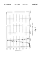
- FIG. 7 is a histogram for high air and water flow rates at a vertical inclination.
- FIG. 8 is a histogram depicting optional interactive manipulation of sigma level selection used in the data reduction method of the present invention.
- Tool string 11 is used for making initial fluid holdup measurements and radioactive fluid density measurements which are used to complement the initial holdup measurements.
- tool string 11 may be generally conventional, but novel data acquisition and reduction algorithms are presented which provide for improved measurements in multi-component flow.
- new tool strings may also be adapted to operate with the new data acquisition and reduction algorithms of the present invention.
- Tool string 11 is essentially that described in U.S. Pat. No. 5,531,112, which is hereby incorporated, and includes a cable head 13, telemetry section 15, fluid holdup tool 17, density tool 19, deflector flowmeter 21, and full bore flowmeter 23.
- Bow spring centralizers 25 are included along tool string 11 for centering tool string 11 within a well.
- Fluid holdup tool 17 includes an upper section 27 and a lower section 29.
- Three caliper arms 31 radially extend from lower section 29 of fluid holdup tool 17.
- Each arm 31 has mounted at its tip a flow sensor (electrical conductivity, thermal conductivity, or acoustic).
- the arms rotate about the axis of tool string 11, at varying angles or distances.
- the sensors are synchronized with control electronics to measure fluid flow at different localized regions, allowing detection of variations in fluid properties attributable to flow constituents. See the '112 patent for further details.
- An appropriate fluid holdup tool is available from Computalog Research, Inc. (assignee of the present invention), referred to as the Fluid Profiling Tool (FPT).
- FPT Fluid Profiling Tool
- the FPT is compatible with the FlexStak multiplexing scheme (FlexStak is a trademark of Computalog).
- a personal computer or similar device may be used for data acquisition and reduction.
- Tool control can be provided by the same computer or using a different microprocessor unit.
- the data acquired by fluid holdup tool 17 at multiple polar angles and radii can be reduced to a plot 40 similar to that shown in FIG. 2.
- Arms 31 can be moved using an automated routine which eases the data gathering task. If denser sampling is required, as when precisely locating a stratified flow boundary, a manual routine can be provided.
- a hydrocarbon scaling bar 42 can also be included to provide a visual indication of holdup values.
- the holdup values at each point in plot 40 represents the duty cycle of detected conductive/nonconductive fluids.
- the sensors have a near-binary response, and largely alternate between two specific output levels as water and hydrocarbon mixtures pass over them. A 50% duty cycle at the hydrocarbon (gas or oil) output level would represent a hydrocarbon holdup value of 0.5.
- the holdup of any fluid thus has a continuous possible range of 0 to 1.0, and simply represents the volumetric percentage of the fluid.
- the initial holdup value for the fluid (at the particular depth/location) is computed by multiplying the percentage area of a given individual track/sector segment 43 (relative to the total area in plot 40) with the mean holdup value for that segment, and then summing the results for all segments.
- This initial holdup value referred to herein as Y h .sbsb.-- FPT
- Y h .sbsb.-- total is one component of the actual, total holdup.
- a hydrocarbon threshold is the value used to determine whether a transition has occurred from water to hydrocarbon (and thus the binary state of the output of the sensors).
- the threshold yielding the best response was empirically found to be about 90% of the water/hydrocarbon span (the frequency range between the water and hydrocarbon indications). For example, if the input frequency of the sensors for water indication is 30 kHz, and the gas indication input frequency is 17 kHz, then the hydrocarbon threshold used is about 28.7 kHz.
- the other component of Y h .sbsb.-- total is derived from density tool 19, and is referred to herein as Y h .sbsb.-- FD .
- Density tool 19 is preferably a radioactive (gamma--gamma) tool having conventional components.
- a suitable density tool is available from Computalog, referred to as the FlexStak Radioactive Fluid Density (RFD) tool. While prior art tools use density measurements in a complementary fashion, those methods simply use counts to determine average downhole densities, and a nonlinear mapping or correction function then maps the measured density into a holdup value.
- the present invention uses the count information to calculate the holdup contribution from the density measurement (Y h .sbsb.-- FD ) by inferring a maximum heavy-phase density (MHPD).
- the MHPD is determined by generating a histogram of brief (e.g., 100 millisecond) samples continuously returned by density tool 19, and searching for the lowest valid instantaneous count rate acquired during the period.
- the count rate is "valid" if it has a nonzero occurrence value and is contiguous with the heavy phase peak (i.e., there is no intervening count rate that has a nonzero occurrence value).
- an algorithm discussed further below is used to establish the center of the count rate for the MHPD.
- the center of the count rate for the MHPD is converted using calibration into the MHPD value, e.g., in grams per cubic centimeter (gram/cm 3 ).
- the MHPD is nearly equal to Y h .sbsb.-- PFD . Since the density of water is one gram per cubic centimeter, the numeric value of the density measurement (which is also in grams per cubic centimeter) corresponds to the holdup percentage.
- the MHPD is based on the notion that particles of hydrocarbons finely dispersed in the water component will have lifetimes that far exceed the transit time required to pass through an instrument measuring volume.
- the use of MHPD is an acknowledgement that pure water does not exist in downhole flowing conditions, and usually has some entrained particles in it.
- the MHPD is therefore used to determine the level of small hydrocarbon particles dispersed in the heavy component of the flow.
- This principle could also be applied to a rock matrix, rather than a fluid, where the local rock composition is changing with respect to depth; the method could be used to infer the maximum formation density of the global rock matrix into which lower density inclusions are dispersed (the reverse of this method could be used if the inclusions were of higher density than the matrix).
- the center of the count rate for the MHPD is determined by moving some number of standard deviations (of the heavy component peak) to the right of, or upwards from, the lowest valid count rate.
- standard deviations of the heavy component peak
- a level of three standard deviations (3 ⁇ ) is generally optimum.
- sigma levels of 3.0 ⁇ -4.0 ⁇ are generally most accurate.
- the MHPD may be determined iteratively using an arbitrary seed number, guessing what the lowest expected count should be, and incrementing the number by a small amount if the lowest expected count deviates from the actual lowest count by more than some predetermined value.
- For multi-component flow there is an apparent blurring of the statistical peak, perhaps due in part to the statistical behavior of the finely dispersed hydrocarbon inclusions.
- FIG. 3 shows the density tool's counting histogram for single component water
- FIG. 4 shows a histogram for single component air.
- the x-axis of each figure shows the instantaneous count rate and the y-axis shows the number of occurrences of each count rate, within the sampling period (3 to 5 minutes).
- FIG. 5 shows a histogram acquired for a mixture at high water flow and low gas flow; the peak of the left (near-water peak) is much larger than the peak on the right (near-gas peak), and the two peaks are closer than the single component gas and water peaks are.
- FIG. 6 shows the reverse situation, a histogram for low water flow and high gas flow. Again, the peaks have moved toward one another, but now the near-air peak is higher.
- FIG. 7 shows a histogram for high air and water flow rates at a vertical inclination. Extreme turbulence and shearing has almost melded the two peaks into one, as little near-air or near-water
- the preferred sigma level generating the lowest errors in Y h .sbsb.-- total tends to change with the relative position of (distance between) the near-air and near-water peaks; however, determination of the peak positions becomes more difficult as they meld together at higher rates.
- the peaks can be "stripped" by removing the superposition of the two peaks that naturally occurs. The simplest way to do this is to assume that the truncated side of the higher peak is actually symmetrical about its centroid. The shape is accordingly reflected about the centroid, and subtracted from the raw (superposed) graph, which results in two well-defined and symmetrical peaks emerging. Determination of their positions is further facilitated by some averaging level being placed upon the histogram before stripping (10 level is exemplary).
- a linear regression of the distance between the peaks can be used to select an acceptable sigma level. This regression is thus based on the value of (C l -C h )/(C a -C w ), referred to herein as the peak ratio, where C l is the count rate for the light phase (near-air) peak, C h is the count rate for the heavy phase (near-water) peak, C a is the calibration value of the air count rate and C w is the calibration value of the water count rate.
- the regression is preferably based on a large set of experimental data. Its validity does not depend upon prior knowledge of any well being interrogated, and uses as its input only information gleaned from the data itself.
- This regression method for selecting an appropriate sigma level breaks down when only one peak is present, as with single component gas or water flow, since there is only one peak. Such situations can be automatically recognized, however, and the default value of 3 ⁇ is used.
- the selection of the sigma level can be manipulated interactively, as shown in FIG. 8.
- the data depicted there are non-smoothed from a high air rate test.
- This utility (visual presentation of the histogram) can be generated during the data reduction process, and allow manual override of otherwise automatic peak selection. Especially at the difficult boundaries of low gas flow at near horizontal, this manual interaction is valuable in conjunction with the cross-section image. In the case where only one peak is recognized in the histogram, but the cross-section notes significant gas along the top of the flow pipe, the chance for maximum error arises, as the density tool may no longer intercept a representative sample to determine MHPD accurately. In this case, operator. judgment may be used to select an optimum sigma level.
- the present invention deviates from the popular prior art approach of characterizing the multi-component flow response of sensors in a flow loop, which can lead to problems since even minor differences in flow loop and field conditions can greatly affect the usefulness of correction charts. Instead, the data reduction method of the present invention avoids any dependence upon prior knowledge of well conditions, including inclination.
- a FPT sensor sample interval of 10 milliseconds (10 times faster than fluid density) hydrocarbon transients of less than 10 ms are seen as deflections of less than full scale, which is an artifact of the sampling speed.
- Some periods that indicate hydrocarbons may last for several contiguous 10 ms periods.
- a histogram of occurrences of duration pins in 10 ms intervals may be used to provide additional qualitative information related to the flow regime.
- contiguous hydrocarbon periods of several seconds may occur.
- a span of 500 (10 ms) bins may be useful to cover a range of hydrocarbon duration from 10 ms to five seconds.
Landscapes
- Physics & Mathematics (AREA)
- Life Sciences & Earth Sciences (AREA)
- Engineering & Computer Science (AREA)
- Geology (AREA)
- Mining & Mineral Resources (AREA)
- Geophysics (AREA)
- Environmental & Geological Engineering (AREA)
- Fluid Mechanics (AREA)
- General Life Sciences & Earth Sciences (AREA)
- Geochemistry & Mineralogy (AREA)
- Chemical & Material Sciences (AREA)
- Health & Medical Sciences (AREA)
- Chemical Kinetics & Catalysis (AREA)
- General Chemical & Material Sciences (AREA)
- Oil, Petroleum & Natural Gas (AREA)
- Acoustics & Sound (AREA)
- Food Science & Technology (AREA)
- Medicinal Chemistry (AREA)
- Analytical Chemistry (AREA)
- Biochemistry (AREA)
- General Health & Medical Sciences (AREA)
- General Physics & Mathematics (AREA)
- Immunology (AREA)
- Pathology (AREA)
- Measuring Volume Flow (AREA)
Abstract
Description
Y.sub.h.sbsb.--.sub.total =Y.sub.h.sbsb.--.sub.FD +[Y.sub.h.sbsb.--.sub.FPT ×(1-Y.sub.h.sbsb.--.sub.FD)]
Claims (28)
Y.sub.h.sbsb.--.sub.total =Y.sub.h.sbsb.--.sub.FD +[Y.sub.h.sbsb.--.sub.FPT ×(1-Y.sub.h.sbsb.--.sub.FD)]
Y.sub.h.sbsb.--.sub.total =Y.sub.h.sbsb.--.sub.FD +[Y.sub.h.sbsb.--.sub.FPT ×(1-Y.sub.h.sbsb.--.sub.FD)]
Y.sub.h.sbsb.--.sub.total =Y.sub.h.sbsb.--.sub.FD +[Y.sub.h.sbsb.--.sub.FPT ×(1-Y.sub.h.sbsb.--.sub.FD)]
Priority Applications (1)
| Application Number | Priority Date | Filing Date | Title |
|---|---|---|---|
| US08/939,247 US6028307A (en) | 1997-09-28 | 1997-09-28 | Data acquisition and reduction method for multi-component flow |
Applications Claiming Priority (1)
| Application Number | Priority Date | Filing Date | Title |
|---|---|---|---|
| US08/939,247 US6028307A (en) | 1997-09-28 | 1997-09-28 | Data acquisition and reduction method for multi-component flow |
Publications (1)
| Publication Number | Publication Date |
|---|---|
| US6028307A true US6028307A (en) | 2000-02-22 |
Family
ID=25472817
Family Applications (1)
| Application Number | Title | Priority Date | Filing Date |
|---|---|---|---|
| US08/939,247 Expired - Lifetime US6028307A (en) | 1997-09-28 | 1997-09-28 | Data acquisition and reduction method for multi-component flow |
Country Status (1)
| Country | Link |
|---|---|
| US (1) | US6028307A (en) |
Cited By (18)
| Publication number | Priority date | Publication date | Assignee | Title |
|---|---|---|---|---|
| US6286360B1 (en) | 1999-02-25 | 2001-09-11 | Metasensors, Inc. | Methods and apparatus for real time fluid analysis |
| US6427530B1 (en) * | 2000-10-27 | 2002-08-06 | Baker Hughes Incorporated | Apparatus and method for formation testing while drilling using combined absolute and differential pressure measurement |
| US6427521B2 (en) * | 1998-07-10 | 2002-08-06 | Metso Field Systems Oy. | Method and measuring arrangement for measuring gas content of fluid |
| WO2008149124A2 (en) * | 2007-06-08 | 2008-12-11 | Sondex Wireline Limited | Apparatus for determining the concentration of a conductive fluid present in a fluid filled borehole |
| US7603236B2 (en) | 2006-08-21 | 2009-10-13 | Schlumberger Technology Corporation | Method to determine fluid phase distribution and quantify holdup in a wellbore |
| US20160003032A1 (en) * | 2014-07-07 | 2016-01-07 | Conocophillips Company | Matrix temperature production logging tool |
| CN107676076A (en) * | 2017-04-10 | 2018-02-09 | 吉林大学 | Ice auger strain-type aperture logging instrument |
| NO342174B1 (en) * | 2001-05-30 | 2018-04-09 | Schlumberger Holdings | Method for estimating water conductivity or water salinity in a multiphase mixture |
| US10012763B2 (en) | 2013-11-07 | 2018-07-03 | Halliburton Energy Services, Inc. | Utilizing fluid phase behavior interpretation to increase sensor measurement information accuracy |
| US10941647B2 (en) | 2014-07-07 | 2021-03-09 | Conocophillips Company | Matrix temperature production logging tool and use |
| CN113431553A (en) * | 2021-08-10 | 2021-09-24 | 大庆亿莱检验检测技术服务有限公司 | Horizontal well multiphase fluid measuring device |
| US11313225B2 (en) | 2020-08-27 | 2022-04-26 | Saudi Arabian Oil Company | Coring method and apparatus |
| US11460443B2 (en) | 2021-02-18 | 2022-10-04 | Saudi Arabian Oil Company | Fluid analysis systems and methods in oil and gas applications |
| WO2023113848A1 (en) * | 2021-12-14 | 2023-06-22 | Halliburton Energy Services, Inc. | Compensated formation saturation using assisted physics and neural networks |
| US20230220771A1 (en) * | 2022-01-11 | 2023-07-13 | Halliburton Energy Services, Inc. | Fluid holdup monitoring in downhole fluid sampling tools |
| US11713651B2 (en) | 2021-05-11 | 2023-08-01 | Saudi Arabian Oil Company | Heating a formation of the earth while drilling a wellbore |
| US11802827B2 (en) | 2021-12-01 | 2023-10-31 | Saudi Arabian Oil Company | Single stage MICP measurement method and apparatus |
| US12049807B2 (en) | 2021-12-02 | 2024-07-30 | Saudi Arabian Oil Company | Removing wellbore water |
Citations (9)
| Publication number | Priority date | Publication date | Assignee | Title |
|---|---|---|---|---|
| US4441361A (en) * | 1981-10-02 | 1984-04-10 | Dresser Industries, Inc. | Method and apparatus for measurement of fluid density and flow rates in multi-phase flow regimes |
| US4939362A (en) * | 1988-11-28 | 1990-07-03 | Texaco Inc. | Borehole fluid density well logging means and method |
| US5012091A (en) * | 1990-02-27 | 1991-04-30 | Halliburton Logging Services, Inc. | Production logging tool for measuring fluid densities |
| US5359195A (en) * | 1992-02-26 | 1994-10-25 | Halliburton Logging Services, Inc. | Gas hold up tool for use in cased well boreholes |
| US5361632A (en) * | 1992-04-24 | 1994-11-08 | Chevron Research And Technology Company | Method and apparatus for determining multiphase holdup fractions using a gradiomanometer and a densitometer |
| US5375465A (en) * | 1993-04-15 | 1994-12-27 | Royal Wireline, Inc. | Method for gas/liquid well profiling |
| US5531112A (en) * | 1994-05-20 | 1996-07-02 | Computalog U.S.A., Inc. | Fluid holdup tool for deviated wells |
| US5552598A (en) * | 1995-06-06 | 1996-09-03 | Halliburton Company | Determination of downhole flow regime in a horizontal wellbore by using center sample and fullbore gas-liquid holdup measurements |
| US5631413A (en) * | 1994-05-20 | 1997-05-20 | Computalog Usa, Inc. | Fluid holdup tool and flow meter for deviated wells |
-
1997
- 1997-09-28 US US08/939,247 patent/US6028307A/en not_active Expired - Lifetime
Patent Citations (9)
| Publication number | Priority date | Publication date | Assignee | Title |
|---|---|---|---|---|
| US4441361A (en) * | 1981-10-02 | 1984-04-10 | Dresser Industries, Inc. | Method and apparatus for measurement of fluid density and flow rates in multi-phase flow regimes |
| US4939362A (en) * | 1988-11-28 | 1990-07-03 | Texaco Inc. | Borehole fluid density well logging means and method |
| US5012091A (en) * | 1990-02-27 | 1991-04-30 | Halliburton Logging Services, Inc. | Production logging tool for measuring fluid densities |
| US5359195A (en) * | 1992-02-26 | 1994-10-25 | Halliburton Logging Services, Inc. | Gas hold up tool for use in cased well boreholes |
| US5361632A (en) * | 1992-04-24 | 1994-11-08 | Chevron Research And Technology Company | Method and apparatus for determining multiphase holdup fractions using a gradiomanometer and a densitometer |
| US5375465A (en) * | 1993-04-15 | 1994-12-27 | Royal Wireline, Inc. | Method for gas/liquid well profiling |
| US5531112A (en) * | 1994-05-20 | 1996-07-02 | Computalog U.S.A., Inc. | Fluid holdup tool for deviated wells |
| US5631413A (en) * | 1994-05-20 | 1997-05-20 | Computalog Usa, Inc. | Fluid holdup tool and flow meter for deviated wells |
| US5552598A (en) * | 1995-06-06 | 1996-09-03 | Halliburton Company | Determination of downhole flow regime in a horizontal wellbore by using center sample and fullbore gas-liquid holdup measurements |
Non-Patent Citations (1)
| Title |
|---|
| Allen R. Young, Scot A. Johnson, A New Production Logging Tool for Determining Holdups, SPE 38652. * |
Cited By (25)
| Publication number | Priority date | Publication date | Assignee | Title |
|---|---|---|---|---|
| US6427521B2 (en) * | 1998-07-10 | 2002-08-06 | Metso Field Systems Oy. | Method and measuring arrangement for measuring gas content of fluid |
| US6286360B1 (en) | 1999-02-25 | 2001-09-11 | Metasensors, Inc. | Methods and apparatus for real time fluid analysis |
| US6427530B1 (en) * | 2000-10-27 | 2002-08-06 | Baker Hughes Incorporated | Apparatus and method for formation testing while drilling using combined absolute and differential pressure measurement |
| NO342174B1 (en) * | 2001-05-30 | 2018-04-09 | Schlumberger Holdings | Method for estimating water conductivity or water salinity in a multiphase mixture |
| US7603236B2 (en) | 2006-08-21 | 2009-10-13 | Schlumberger Technology Corporation | Method to determine fluid phase distribution and quantify holdup in a wellbore |
| WO2008149124A2 (en) * | 2007-06-08 | 2008-12-11 | Sondex Wireline Limited | Apparatus for determining the concentration of a conductive fluid present in a fluid filled borehole |
| WO2008149124A3 (en) * | 2007-06-08 | 2009-04-16 | Sondex Wireline Ltd | Apparatus for determining the concentration of a conductive fluid present in a fluid filled borehole |
| CN101842693A (en) * | 2007-06-08 | 2010-09-22 | 桑德克斯有线有限公司 | Apparatus for determining the concentration of a conductive fluid present in a fluid filled borehole |
| US20100299068A1 (en) * | 2007-06-08 | 2010-11-25 | Guy Harvey Mason | Apparatus for determining the concentration of a conductive fluid present in a fluid filled borehole |
| US8849572B2 (en) | 2007-06-08 | 2014-09-30 | Sondex Wireline Limited | Apparatus for determining the concentration of a conductive fluid present in a fluid filled borehole |
| US10012763B2 (en) | 2013-11-07 | 2018-07-03 | Halliburton Energy Services, Inc. | Utilizing fluid phase behavior interpretation to increase sensor measurement information accuracy |
| US20160003032A1 (en) * | 2014-07-07 | 2016-01-07 | Conocophillips Company | Matrix temperature production logging tool |
| US10941647B2 (en) | 2014-07-07 | 2021-03-09 | Conocophillips Company | Matrix temperature production logging tool and use |
| CN107676076A (en) * | 2017-04-10 | 2018-02-09 | 吉林大学 | Ice auger strain-type aperture logging instrument |
| US11313225B2 (en) | 2020-08-27 | 2022-04-26 | Saudi Arabian Oil Company | Coring method and apparatus |
| US11460443B2 (en) | 2021-02-18 | 2022-10-04 | Saudi Arabian Oil Company | Fluid analysis systems and methods in oil and gas applications |
| US11713651B2 (en) | 2021-05-11 | 2023-08-01 | Saudi Arabian Oil Company | Heating a formation of the earth while drilling a wellbore |
| CN113431553B (en) * | 2021-08-10 | 2021-12-03 | 大庆亿莱检验检测技术服务有限公司 | Horizontal well multiphase fluid measuring device |
| CN113431553A (en) * | 2021-08-10 | 2021-09-24 | 大庆亿莱检验检测技术服务有限公司 | Horizontal well multiphase fluid measuring device |
| US11802827B2 (en) | 2021-12-01 | 2023-10-31 | Saudi Arabian Oil Company | Single stage MICP measurement method and apparatus |
| US12049807B2 (en) | 2021-12-02 | 2024-07-30 | Saudi Arabian Oil Company | Removing wellbore water |
| WO2023113848A1 (en) * | 2021-12-14 | 2023-06-22 | Halliburton Energy Services, Inc. | Compensated formation saturation using assisted physics and neural networks |
| US11994647B2 (en) | 2021-12-14 | 2024-05-28 | Halliburton Energy Services, Inc. | Compensated formation saturation using assisted physics and neural networks |
| US20230220771A1 (en) * | 2022-01-11 | 2023-07-13 | Halliburton Energy Services, Inc. | Fluid holdup monitoring in downhole fluid sampling tools |
| US12055038B2 (en) * | 2022-01-11 | 2024-08-06 | Halliburton Energy Services, Inc. | Fluid holdup monitoring in downhole fluid sampling tools |
Similar Documents
| Publication | Publication Date | Title |
|---|---|---|
| US6028307A (en) | Data acquisition and reduction method for multi-component flow | |
| CA2172440C (en) | A method and apparatus for locally measuring flow parameters of a multiphase fluid | |
| US5361632A (en) | Method and apparatus for determining multiphase holdup fractions using a gradiomanometer and a densitometer | |
| US5561245A (en) | Method for determining flow regime in multiphase fluid flow in a wellbore | |
| US6585044B2 (en) | Method, system and tool for reservoir evaluation and well testing during drilling operations | |
| US5513528A (en) | Logging while drilling method and apparatus for measuring standoff as a function of angular position within a borehole | |
| US7580797B2 (en) | Subsurface layer and reservoir parameter measurements | |
| US6885942B2 (en) | Method to detect and visualize changes in formation parameters and borehole condition | |
| US9091781B2 (en) | Method for estimating formation permeability using time lapse measurements | |
| US6216532B1 (en) | Gas flow rate measurement | |
| US7279677B2 (en) | Measuring wellbore diameter with an LWD instrument using compton and photoelectric effects | |
| US7523002B2 (en) | Method and system for cause-effect time lapse analysis | |
| US5323648A (en) | Formation evaluation tool | |
| US5586027A (en) | Method and apparatus for determining flow rates in multi-phase fluid flow mixtures | |
| US10378349B2 (en) | Methods of plotting advanced logging information | |
| MX2008015642A (en) | Standoff correction for lwd density measurement. | |
| EP1936112B1 (en) | Method, system and tool for reservoir evaluation and well testing during drilling operations | |
| US7603236B2 (en) | Method to determine fluid phase distribution and quantify holdup in a wellbore | |
| US5633470A (en) | Velocity and holdup determination method for stratified gas-liquid flow in highly inclined conduits | |
| US20230349285A1 (en) | Measuring water level in highly deviated or horizontal hydrocarbon well sections | |
| Stuivenwold et al. | New instrumentation for managing sand-problem prone fields | |
| Bearden et al. | Interpretation of injectivity profiles in irregular boreholes | |
| Frisch et al. | Gas holdup tool applications in production logging | |
| Carlson et al. | Judging the Quality of Continuous Spinner Flowmeter Logs |
Legal Events
| Date | Code | Title | Description |
|---|---|---|---|
| AS | Assignment |
Owner name: COMPUTALOG RESEARCH, INC., TEXAS Free format text: ASSIGNMENT OF ASSIGNORS INTEREST;ASSIGNORS:YOUNG, ALLEN R.;JOHNSON, SCOT A.;REEL/FRAME:010874/0855;SIGNING DATES FROM 19970922 TO 19970926 |
|
| STCF | Information on status: patent grant |
Free format text: PATENTED CASE |
|
| CC | Certificate of correction | ||
| FEPP | Fee payment procedure |
Free format text: PAYOR NUMBER ASSIGNED (ORIGINAL EVENT CODE: ASPN); ENTITY STATUS OF PATENT OWNER: LARGE ENTITY |
|
| FPAY | Fee payment |
Year of fee payment: 4 |
|
| AS | Assignment |
Owner name: COMPUTALOG USA, INC., TEXAS Free format text: ASSIGNMENT OF ASSIGNORS INTEREST;ASSIGNOR:COMPUTALOG RESEARCH, INC.;REEL/FRAME:016446/0373 Effective date: 19910701 |
|
| AS | Assignment |
Owner name: PRECISION DRILLING TECHNOLOGY SERVICES GROUP, INC. Free format text: CHANGE OF NAME;ASSIGNOR:COMPUTALOG LTD.;REEL/FRAME:017275/0188 Effective date: 20011231 |
|
| AS | Assignment |
Owner name: PRECISION ENERGY SERVICES, LTD., CANADA Free format text: CHANGE OF NAME;ASSIGNOR:PRECISION DRILLING TECHNOLOGY SERVICES GROUP, INC.;REEL/FRAME:016345/0078 Effective date: 20050404 |
|
| AS | Assignment |
Owner name: PRECISION DRILLING TECHNOLOGY SERVICES GROUP, INC. Free format text: CHANGE OF NAME;ASSIGNOR:COMPUTALOG LTD.;REEL/FRAME:017230/0980 Effective date: 20011231 |
|
| AS | Assignment |
Owner name: PRECISION ENERGY SERVICES ULC, CANADA Free format text: ASSIGNMENT OF ASSIGNORS INTEREST;ASSIGNOR:PRECISION ENERGY SERVICES LTD.;REEL/FRAME:017507/0031 Effective date: 20060331 |
|
| AS | Assignment |
Owner name: WEATHERFORD CANADA PARTNERSHIP, CANADA Free format text: ASSIGNMENT OF ASSIGNORS INTEREST;ASSIGNOR:PRECISION ENERGY SERVICES ULC;REEL/FRAME:017527/0191 Effective date: 20060421 |
|
| FPAY | Fee payment |
Year of fee payment: 8 |
|
| FEPP | Fee payment procedure |
Free format text: PAYOR NUMBER ASSIGNED (ORIGINAL EVENT CODE: ASPN); ENTITY STATUS OF PATENT OWNER: LARGE ENTITY Free format text: PAYER NUMBER DE-ASSIGNED (ORIGINAL EVENT CODE: RMPN); ENTITY STATUS OF PATENT OWNER: LARGE ENTITY |
|
| FPAY | Fee payment |
Year of fee payment: 12 |