US602002A - John daniel forster - Google Patents
John daniel forster Download PDFInfo
- Publication number
- US602002A US602002A US602002DA US602002A US 602002 A US602002 A US 602002A US 602002D A US602002D A US 602002DA US 602002 A US602002 A US 602002A
- Authority
- US
- United States
- Prior art keywords
- coin
- gas
- bar
- slide
- plunger
- Prior art date
- Legal status (The legal status is an assumption and is not a legal conclusion. Google has not performed a legal analysis and makes no representation as to the accuracy of the status listed.)
- Expired - Lifetime
Links
- 238000010276 construction Methods 0.000 description 1
- 230000000994 depressogenic effect Effects 0.000 description 1
- 230000037431 insertion Effects 0.000 description 1
- 238000003780 insertion Methods 0.000 description 1
- 210000003141 lower extremity Anatomy 0.000 description 1
- 230000000284 resting effect Effects 0.000 description 1
- 230000035939 shock Effects 0.000 description 1
Images

Classifications
-
- G—PHYSICS
- G07—CHECKING-DEVICES
- G07F—COIN-FREED OR LIKE APPARATUS
- G07F17/00—Coin-freed apparatus for hiring articles; Coin-freed facilities or services
- G07F17/14—Coin-freed apparatus for hiring articles; Coin-freed facilities or services for fastenings for doors; for turnstiles
Definitions
- I-rwenZF/r VZWAZLV Wiihesses; %/%L 4.
- This invention refers to improved mechanism, acting in conjunction with any ordinary or useful meter or measuring apparatus, whereby a predeterminedvolume of gas is allowed to pass for the use of the consumer, the mechanism being brought into action by or through the insertion of a coin or token, the latter acting to free the movable parts, which continue in motion until the proper quantity of gas has been delivered.
- the mechanism then causes the coin to pass into a suitable receptacle and shuts off the gas-supply, it being necessary to insert another cointo cause the mechanism to again act and deliver a 'second measured quantity.
- Several coins may be inserted at one time and the mechanism thereby caused to act continuously until a quantity of gas is delivered proportionate to the number of coins placedv in a container.
- FIG. 1 being a side elevation of the mechanism
- Fig. 2, a plan of same
- Fig. 3, a side sectional elevation of the coin-container
- Fig. 4 a plan view of the parts shown in Fig. 3, but with the coin-container itself removed
- Fig. 5, a cross-section on the line X Y of Fig. 4E
- Fig. 6, a side elevation of some of the parts shown at Fig. 1, but in an intermediate position.
- gas from the main passes into a cylinder A by the passage A, and by a passage A it passes therefrom through the gas-meter for the consumers use.
- a valve A In the cylinder A there is a division having an aperture controlled by a valve A as shown by dotted lines, and this valve normally closes the passage between the entrance and exit passages A and A
- the valve A is mounted on a spindle A passing to the exterior of the cylinder A, and is held open Serial No. 641,622. (No model.)
- a shaft B, Fig. 2 carrying a pinion B, gearing with a tooth-wheel 0, carried in suitable bearings, which latter has a crank-arm 0, provided with a crank-pin C the latter being thus revolved at a speed proportional to that of the index mechanism of the gas-meter.
- the crank-pin 0 passes through aslot D in a pivoted and sliding bar D, the slotted end of the bar being somewhat heavier or more weighted than its opposite end.
- a projection D which when the gas is shut off, as shown at Fig. 1, is in contact with the conical end A of the spindle of the valve A to retain the latter in its closed position.
- the barD is pivoted at D to a horizontallymovable slide E, and the end D of the bar extends upward (when the gas is shut off) through an aperture E, Figs. 3, 4, and 5, in the said slide E.
- a circular coin-receiver G Above the slide E, which is carried by a guide-plate F, is mounted a circular coin-receiver G, containing a plunger H.
- the plunger H is operated by means of a rod or handle H, the base of which has a flange h thereon, which fits into a recess h in the upper side of said plunger and has a slight vertical movement in said recess.
- a coil-spring H interposed between the lower end of said rod H and the bottom of said recess forms a cushion to prevent too violent shocks upon the arm D when the handle or rod H is suddenly depressed, as in starting the mechanism.
- the plunger H is formed on its under face with downwardly extending side arms or wings H which wings H when there is no coin beneath the plunger, rest on the guide F of the slide E and prevent the under face of the plunger H from coming into contact with the upwardly-extending part D of the arm D of the bar D.
- the front end of the slide E is cut away sufficiently to allow. the coin to pass between its two arms, while the guide-plate F at the part beneath the coin-receiver G, although partly cut away, as shown by dotted lines F, Fig. 4:, will still retain a coin; but such opening, as in dotted line F, is increased in size 5 forward of the receiver G, so that although the coin will not fall away when lying upon the guide-plate F immediately beneath the receiver G upon the slide ebeing drawn away, yet such coin will pass through upon being to pushed by a forward motion of the slide E from beneath the receiver G.
- the coins are inserted into the receiver G by the aperture G.
- the action is as follows: Supposing the gas to be cut OE and no coins being in the coincontainer, the plunger H is first lifted. A coin is then inserted beneath same through the aperture G. This coin falls to the bottom of the container, resting upon the upturned" end D of the bar D. The plunger His then lowered. Its wings H act upon the coin, which latter by pressure forces the endD downward. The bar D is rocking on its pivot D the projection D raised, the valve thereby being released, the gas-supply pipe opened, and the meter mechanism released for action.
- the shaft B, Fig. 2 revolved from the meter-index mechanism, actuates thecrank-pinG by the gearing in the direc tion of the arrow, Fig.
- crank-pin revolved by the index mechanism of the meter and connected to said bar for operating the latter; means operated by said bar :'to open'and close a gas-supply pipe; and a projection on said bar adapted to be operated by said plunger through the medium of an inserted coin, substantially as described.
- a prepayment mechanism for gas-supply the combination with a coin-receptacle; a plunger workingin said receptacle a slotted guide-plate beneath said receptacle; a delivery-slide working upon said guide-plate; a rocking bar pivoted to said delivery-slide; a
- crank-pin revolved by the index mechanism of the meter and connected to said rocking bar for operating the latter; means operated by said bar to open and close a gas-supply pipe; and an extension 011 said bar adapted to beoperated by said plunger through the medium of aninserted coin, substantially as described.
- rocking bar pivotcd'to saiddelivery-slide; a ,cranlopin revolved by theindex mechanism :of themete'r and connected to said rocking 1 bar for operating the latter; .a spring-plunger connected to a valve in the gas-main normally holding said valve open; a projection onsaid rocking bar adapted to strike said valve-plunger and close saidvalve when at rest; and an extension on said rocking bar adapted to be operated by said piston through the medium of an inserted coin,substantially as described.
Landscapes
- Physics & Mathematics (AREA)
- General Physics & Mathematics (AREA)
- Measuring Volume Flow (AREA)
Description
2 Sheets-Sheet 1.
(No Model.)
J. D. FORSTER. PREPAID GAS SUPPLY METER.
No. 602,002. Patented Apr. 5,1898.
With Lessee: Wig/Z01:
. om a/ Malay-9.
(No Model.) 2 Sheets-Sheet 2,
\ J. D. PORSTER..
PREPAID GAS'SUPPLY METER.
Patented Apr. 5, 1898.
W), I ditorzwys.
I-rwenZF/r: VZWAZLV Wiihesses; %/%L 4.
.. NITED STATES JOHN DANIEL FORSTER,
OF LONDON, ENGLAND.
PREPAlD-GAS-SUPPLY METER.
SPECIFICATION formingpart of Letters Patent No. 602,002, dated April 1898.
Application filed June 2 1, 18 9 '7.
To all whom it may concern-.-
Be it known that I, JOHN DANIEL FORSTER, a subject of the Queen of Great Britain, residing at London, England, have invented certain new and useful Improvements in Apparatus for Prepaid Gas-Supply; and I do hereby declare the following to be a full, clear, and exact description of the invention, such as will enable others skilled in the art to which it appertains to make and use the same.
This invention refers to improved mechanism, acting in conjunction with any ordinary or useful meter or measuring apparatus, wherebya predeterminedvolume of gas is allowed to pass for the use of the consumer, the mechanism being brought into action by or through the insertion of a coin or token, the latter acting to free the movable parts, which continue in motion until the proper quantity of gas has been delivered. The mechanism then causes the coin to pass into a suitable receptacle and shuts off the gas-supply, it being necessary to insert another cointo cause the mechanism to again act and deliver a 'second measured quantity. Several coins may be inserted at one time and the mechanism thereby caused to act continuously until a quantity of gas is delivered proportionate to the number of coins placedv in a container.
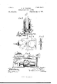
The invention will be readily understood by reference to the accompanying drawings, which illustrate an example of construction, Figure 1 being a side elevation of the mechanism; Fig. 2, a plan of same; Fig. 3, a side sectional elevation of the coin-container; Fig. 4, a plan view of the parts shown in Fig. 3, but with the coin-container itself removed; Fig. 5, a cross-section on the line X Y of Fig. 4E; and Fig. 6, a side elevation of some of the parts shown at Fig. 1, but in an intermediate position.
Referring to the drawings, gas from the main passes into a cylinder A by the passage A, and by a passage A it passes therefrom through the gas-meter for the consumers use. In the cylinder A there is a division having an aperture controlled by a valve A as shown by dotted lines, and this valve normally closes the passage between the entrance and exit passages A and A The valve A is mounted on a spindle A passing to the exterior of the cylinder A, and is held open Serial No. 641,622. (No model.)
for the passage of the gas by a spring A acting against a conical head A on the valvespindle.
. In connection with and operated by the operative mechanism of the gas-meterindex (not illustrated in the accompanying drawings) is a shaft B, Fig. 2, carrying a pinion B, gearing with a tooth-wheel 0, carried in suitable bearings, which latter has a crank-arm 0, provided with a crank-pin C the latter being thus revolved at a speed proportional to that of the index mechanism of the gas-meter. The crank-pin 0 passes through aslot D in a pivoted and sliding bar D, the slotted end of the bar being somewhat heavier or more weighted than its opposite end. At the lower extremity of the slotted end of the bar D there is a projection D which when the gas is shut off, as shown at Fig. 1, is in contact with the conical end A of the spindle of the valve A to retain the latter in its closed position. v
The barD is pivoted at D to a horizontallymovable slide E, and the end D of the bar extends upward (when the gas is shut off) through an aperture E, Figs. 3, 4, and 5, in the said slide E. Above the slide E, which is carried by a guide-plate F, is mounted a circular coin-receiver G, containing a plunger H.
The plunger H is operated by means of a rod or handle H, the base of which has a flange h thereon, which fits into a recess h in the upper side of said plunger and has a slight vertical movement in said recess. A coil-spring H interposed between the lower end of said rod H and the bottom of said recess forms a cushion to prevent too violent shocks upon the arm D when the handle or rod H is suddenly depressed, as in starting the mechanism.
The plunger H is formed on its under face with downwardly extending side arms or wings H which wings H when there is no coin beneath the plunger, rest on the guide F of the slide E and prevent the under face of the plunger H from coming into contact with the upwardly-extending part D of the arm D of the bar D.
The front end of the slide E is cut away sufficiently to allow. the coin to pass between its two arms, while the guide-plate F at the part beneath the coin-receiver G, although partly cut away, as shown by dotted lines F, Fig. 4:, will still retain a coin; but such opening, as in dotted line F, is increased in size 5 forward of the receiver G, so that although the coin will not fall away when lying upon the guide-plate F immediately beneath the receiver G upon the slide ebeing drawn away, yet such coin will pass through upon being to pushed by a forward motion of the slide E from beneath the receiver G. The coins are inserted into the receiver G by the aperture G.
The action is as follows: Supposing the gas to be cut OE and no coins being in the coincontainer, the plunger H is first lifted. A coin is then inserted beneath same through the aperture G. This coin falls to the bottom of the container, resting upon the upturned" end D of the bar D. The plunger His then lowered. Its wings H act upon the coin, which latter by pressure forces the endD downward. The bar D is rocking on its pivot D the projection D raised, the valve thereby being released, the gas-supply pipe opened, and the meter mechanism released for action. The shaft B, Fig. 2, revolved from the meter-index mechanism, actuates thecrank-pinG by the gearing in the direc tion of the arrow, Fig. 1, and lifts the bar, 0 eventually drawing it rearward and allowing the projection D to rest on a guide-plate J as is shown at Fig. 6. The bar and its projection D moving in the direction of the arrow, Fig. 6, upon leaving the guide J falls 5 in front of the valve-spindle and a further motion of the parts closes the valve thereby. During this operation the slide E has been withdrawn from'beneath the coin, the latter has fallen onto the guide plate F, and just 40 before the closing of the valve A the slide E- in its return motion has forced thecoin'so far forwardas to allow it to fall through the aperture of the guide plate F. When anumber of coins are inserted at one time in the 5 container, the described operations are repeated with regard to the bottom'coin, but with the exception that the end'D of'the bar D is held downward by the next upper coin, and consequently the gas is not cut off as long as a coin' remains in the container, so that,supposin g four coins are placed one upon the'other in the coin-container,f0ur times the volume of gas will be continually delivered.
Having now described my invention, what I- desire to claim is 1. In apparatus for prepayin g gas-supply a crank-pin, revolved by the index mechanism of ameter, a bar, operated by the'crank-pin, aprojeotion on the bar acting to open and close agas-supply pipe fromthe main to'the meter, trunnions onthe bar pivoted on a delivery-slide of coin-control]edmechanism and au'extension of the bar by which the latter may be rocked to open thevalve and allow themeter mechanism toact, such-rocking of the'bar being effected by a plunger through themedium of an insertedcoin, substantially as and for the purposes described.
2. In a prepayment mechanism for gas-supply, the combination with a coin-receptacle; a plunger working in said receptacle; a delivery-slide also Working in said receptacle;
a rocking bar pivoted to said delivery-slide;
i a crank-pin revolved by the index mechanism of the meter and connected to said bar for operating the latter; means operated by said bar :'to open'and close a gas-supply pipe; and a projection on said bar adapted to be operated by said plunger through the medium of an inserted coin, substantially as described.
3. In a prepayment mechanism for gas-supply, the combination with a coin-receptacle; a plunger workingin said receptacle a slotted guide-plate beneath said receptacle; a delivery-slide working upon said guide-plate; a rocking bar pivoted to said delivery-slide; a
crank-pin revolved by the index mechanism of the meter and connected to said rocking bar for operating the latter; means operated by said bar to open and close a gas-supply pipe; and an extension 011 said bar adapted to beoperated by said plunger through the medium of aninserted coin, substantially as described.
4. ha prepayment mechanism for gas-supply, the combination with' a coin-receptacle;
@ a piston working in said receptacle; a delivery-slide also working in said receptacle; a rocking bar pivoted to said delivery-slide; a crank-pin" revolved by the index mechanism of the meter and connected to said bar for operating the latter; a spring-plunger connected to a valve in the gas-main, normally holdingsaid valveopen; a projection on said rocking bar adapted to strike said valve-plunger and close said valve when at rest; and an extension on said bar adapted to be operated by said piston throughthe medium of an inserted'coin, substantially as described.
5. Ina prepayment mechanism for gas-supply, thecombinationwith a coin-receptacle;
.a'piston workingin said receptacle; a slotted guide-plate beneath said receptacle; a'delivcry-slide working upon said guide-plate; a
rocking bar pivotcd'to saiddelivery-slide; a ,cranlopin revolved by theindex mechanism :of themete'r and connected to said rocking 1 bar for operating the latter; .a spring-plunger connected to a valve in the gas-main normally holding said valve open; a projection onsaid rocking bar adapted to strike said valve-plunger and close saidvalve when at rest; and an extension on said rocking bar adapted to be operated by said piston through the medium of an inserted coin,substantially as described.
JOHN DANIEL FORSTER.
lVitnesses:
FREDERIO PRINCE, HENRY DENIS.
Publications (1)
| Publication Number | Publication Date |
|---|---|
| US602002A true US602002A (en) | 1898-04-05 |
Family
ID=2670638
Family Applications (1)
| Application Number | Title | Priority Date | Filing Date |
|---|---|---|---|
| US602002D Expired - Lifetime US602002A (en) | John daniel forster |
Country Status (1)
| Country | Link |
|---|---|
| US (1) | US602002A (en) |
-
0
- US US602002D patent/US602002A/en not_active Expired - Lifetime
Similar Documents
| Publication | Publication Date | Title |
|---|---|---|
| US1681929A (en) | Mixed-beverage-vending apparatus | |
| US602002A (en) | John daniel forster | |
| US654441A (en) | Machine for measuring liquids. | |
| US1183557A (en) | Coin-controlled vending-machine. | |
| US824831A (en) | Vending apparatus. | |
| US624844A (en) | moser | |
| US542762A (en) | Ludwig haas | |
| US1695436A (en) | Gasoline-dispensing device | |
| US936365A (en) | Liquid-vending machine. | |
| US454407A (en) | silkman | |
| US567440A (en) | anderson | |
| US688545A (en) | Counting-machine. | |
| US690475A (en) | Coin-controlled liquid-vending machine. | |
| US1048103A (en) | Vending-machine. | |
| US603104A (en) | Coin-controlled meter | |
| US854097A (en) | Coin-controlled liquid-dispensing apparatus. | |
| US416512A (en) | Vending apparatus | |
| US3446327A (en) | Coin caddy change-making mechanism | |
| US762429A (en) | Coin-operated liquid-vending machine. | |
| US1352645A (en) | Liquid-vending machine | |
| US399643A (en) | Automatic coin-operated device | |
| US631488A (en) | Vending-machine. | |
| GB930925A (en) | Coin-dispensing devices | |
| US1355456A (en) | Perfume-vending machine | |
| US412127A (en) | Henri scitloesing and benjamin degremont |