US6007943A - High temperature electrochemical cell with molten alkali metal anode - Google Patents
High temperature electrochemical cell with molten alkali metal anode Download PDFInfo
- Publication number
- US6007943A US6007943A US09/020,214 US2021498A US6007943A US 6007943 A US6007943 A US 6007943A US 2021498 A US2021498 A US 2021498A US 6007943 A US6007943 A US 6007943A
- Authority
- US
- United States
- Prior art keywords
- cell
- tubes
- cathode
- header
- anode
- Prior art date
- Legal status (The legal status is an assumption and is not a legal conclusion. Google has not performed a legal analysis and makes no representation as to the accuracy of the status listed.)
- Expired - Fee Related
Links
Images


Classifications
-
- H—ELECTRICITY
- H01—ELECTRIC ELEMENTS
- H01M—PROCESSES OR MEANS, e.g. BATTERIES, FOR THE DIRECT CONVERSION OF CHEMICAL ENERGY INTO ELECTRICAL ENERGY
- H01M10/00—Secondary cells; Manufacture thereof
- H01M10/36—Accumulators not provided for in groups H01M10/05-H01M10/34
- H01M10/39—Accumulators not provided for in groups H01M10/05-H01M10/34 working at high temperature
- H01M10/399—Cells with molten salts
-
- H—ELECTRICITY
- H01—ELECTRIC ELEMENTS
- H01M—PROCESSES OR MEANS, e.g. BATTERIES, FOR THE DIRECT CONVERSION OF CHEMICAL ENERGY INTO ELECTRICAL ENERGY
- H01M10/00—Secondary cells; Manufacture thereof
- H01M10/36—Accumulators not provided for in groups H01M10/05-H01M10/34
- H01M10/39—Accumulators not provided for in groups H01M10/05-H01M10/34 working at high temperature
- H01M10/3909—Sodium-sulfur cells
- H01M10/3963—Sealing means between the solid electrolyte and holders
-
- H—ELECTRICITY
- H01—ELECTRIC ELEMENTS
- H01M—PROCESSES OR MEANS, e.g. BATTERIES, FOR THE DIRECT CONVERSION OF CHEMICAL ENERGY INTO ELECTRICAL ENERGY
- H01M10/00—Secondary cells; Manufacture thereof
- H01M10/42—Methods or arrangements for servicing or maintenance of secondary cells or secondary half-cells
- H01M2010/4292—Aspects relating to capacity ratio of electrodes/electrolyte or anode/cathode
-
- Y—GENERAL TAGGING OF NEW TECHNOLOGICAL DEVELOPMENTS; GENERAL TAGGING OF CROSS-SECTIONAL TECHNOLOGIES SPANNING OVER SEVERAL SECTIONS OF THE IPC; TECHNICAL SUBJECTS COVERED BY FORMER USPC CROSS-REFERENCE ART COLLECTIONS [XRACs] AND DIGESTS
- Y02—TECHNOLOGIES OR APPLICATIONS FOR MITIGATION OR ADAPTATION AGAINST CLIMATE CHANGE
- Y02E—REDUCTION OF GREENHOUSE GAS [GHG] EMISSIONS, RELATED TO ENERGY GENERATION, TRANSMISSION OR DISTRIBUTION
- Y02E60/00—Enabling technologies; Technologies with a potential or indirect contribution to GHG emissions mitigation
- Y02E60/10—Energy storage using batteries
Definitions
- THIS INVENTION relates to a high temperature rechargeable electrochemical cell. More particularly the invention relates to such cell which is suitable for high power applications, and the invention relates to a method of making such cell.
- a high temperature rechargeable electrochemical cell which comprises a housing defining an interior space, a ceramic solid electrolyte separator located in the housing and dividing the interior space into an anode compartment and a cathode compartment, an alkali metal active anode material located in the anode compartment, and an active cathode material located in the cathode compartment and electrochemically coupled by the solid electrolyte separator to the active anode material, the cell having an operating temperature at which the active anode material is molten and the solid electrolyte separator being of a material which is a conductor of cations of the active anode material, the solid electrolyte separator comprising a multiplicity of at least 5 ceramic solid electrolyte separator tubes, each tube having an open end and a closed end, the active cathode material being located in the interiors of the tubes and each tube having its open end hermetically sealed to an associated opening leading from the tube into a header space defined by a header comprising
- the multiplicity of tubes will usually amount to at least 10, with the quotient or said combined area/interior space volume relationship being at least 1.5 l -1 .
- the multiplicity of tubes may amount to at least 25, with the quotient or said combined area/interior space volume relationship being at least 2.0 l -1 .
- the active anode material will be sodium, the material of the separator being selected from a suitable ceramic solid-electrolyte conductor of sodium cations, such as ⁇ -alumina or ⁇ "-alumina.
- the header may be of ⁇ -alumina, which may be glass-welded to the open ends of the separator tubes.
- each of the tubes may be of the same length as all the other tubes, the cell having an upright operating attitude in which the tubes are suspended by the header from their open upper ends, the associated openings to which the open ends of the tubes are respectively sealed being provided in a flat ⁇ -alumina panel forming a lower wall of the header, the cell having a cathode current collector which has a multiplicity of downward projections which project from the header downwardly respectively into each of the tubes, to a position at or adjacent the closed lower end of each tube, the cathode current collector serving to connect in parallel individual amounts of active cathode material located in the respective tubes.
- the cell will usually either be of the sodium-sulphur/sulphide/polysulphide type or, preferably, of the alkali metal-transition metal/transition metal halide type, such as the sodium-nickel/nickel chloride type, the sodium-iron/ferrous chloride type, or a combination of the sodium-nickel/nickel chloride type and the sodium-iron/ferrous chloride type.
- the alkali metal-transition metal/transition metal halide type such as the sodium-nickel/nickel chloride type, the sodium-iron/ferrous chloride type, or a combination of the sodium-nickel/nickel chloride type and the sodium-iron/ferrous chloride type.
- the cell may be of the alkali metal-transition metal/transition metal halide type, having a cathode which comprises an electronically conductive electrolyte-permeable porous matrix having a porous interior in which the active cathode material is dispersed in finely-divided particulate and/or thin-layer solid form, the matrix being impregnated by a molten salt electrolyte which saturates the porous interior of the matrix, the downward projections of the cathode current collector being electronically connected to the matrix.
- the cells may have a cathode in which there are nickel and iron in a mass ratio of 88:12-80:20, preferably 86:14-82:18, eg 84:16.
- nickel and iron will be essentially the only transition metals present in the cathode.
- the molten salt electrolyte has a melting point below 170° C., more preferably bellow 160° C.
- the molten salt electrolyte may be a sodium aluminium halide electrolyte, in which there are essentially equal amounts of alkali metal halide and aluminium halide, the aluminium halide:alkali metal halide ratio being at most 1:1.
- the molten salt electrolyte may be a sodium aluminium chloride electrolyte doped by at least one dopant which acts to lower its melting point but which is otherwise inert or at least compatible with the cell cathode environment.
- the cell may have a dopant content in total forming 1-30% by mass of the molten salt electrolyte, typically 3-20% by mass thereof.
- Suitable dopants include zirconium tetrachloride (ZrCl 4 ), hafnium tetrachloride (HfCl 4 ) and suitable quaternary ammonium halide salts, such as the chloride salts, of formula R 4 NAlHal 4 , wherein each R is a hydrocarbon group such as an alkyl group, the R groups being the same or different from one another, and each Hal is a halide anion, which anions may be the same or different from one another, but conveniently all being Cl anions.
- Any ZrCl 4 and the HfCl 4 may each be present in proportions which form 5-10% by mass of the molten salt electrolyte; and any R 4 NAlHal 4 may be present in a proportion which forms 10-30% by mass of the molten salt electrolyte.
- each dopant may be selected from the group consisting of zirconium tetrachloride, hafnium tetrachloride, quaternary ammonium halide salts, and any mixtures thereof, any said tetrahalide salts forming in total 5-10% by mass of the molten salt electrolyte and any said ammonium halide salts forming in total 10-30% by mass of the molten salt electrolyte.
- the housing may be a metal housing, such as a mild steel housing, the housing forming an anode current collector and an anode cell terminal being provided on the housing, the cathode current collector being connected to a cathode terminal which projects outwardly from the housing and is electronically insulated from the housing.
- the cell For close packing of cells alongside one another the cell may have a horizontal cross-section or plan view outline which is selected to permit a plurality of said cells to be close-packed alongside one another, in a close-packing arrangement.
- the cell may have a horizontal cross-section or plan view outline which is square, hexagonal, rectangular or triangular, so that a plurality of the cells can be close-packed alongside one another, in a hexagonal- or square close packing arrangement.
- the tubes may be arranged so that their open upper ends, sealed to the header, which may, for example, comprise a flat ⁇ -alumina header panel, are in a grid arrangement selected from hexagonal grid arrangements and square grid arrangements.
- Each tube may have an outer surface which is enclosed by a thin-walled shim, which may be perforated, coiled around the tube and forming a wick for wicking the molten anode material upwardly over and in contact with the outer surface of the tube.
- a thin-walled shim which may be perforated, coiled around the tube and forming a wick for wicking the molten anode material upwardly over and in contact with the outer surface of the tube.
- the tubes may be arranged in a close-packed arrangement, the tubes defining a multiplicity of at least 6 longitudinally extending spaces therebetween and the cell comprising a multiplicity of anode current collectors in the form of electronically conductive rods located respectively in the spaces between the close-packed tubes.
- the arrangement may be a cubic-close packed arrangement, it is preferably a hexagonal-close packed arrangement.
- the spaces will be bounded, in the case of cubic-close packing, by four tubes and will be bounded, in the case of hexagonal-close packing, by three tubes.
- Each anode current collector rod may fill the associated longitudinally extending space sufficiently to act as a wick for wicking molten anode material upwardly in said associated longitudinally extending space.
- the rods have a dual function, namely wicking molten anode material along the spaces between the tubes, and anode current collecting.
- each tube may be substantially in side-by-side contact with all the tubes adjacent or surrounding it.
- each rod may have a diameter such that it is substantially in contact, along its full length, with the tubes adjacent or surrounding it, although it need not be in contact with all the tubes along its full length, provided that it is close enough thereto to provide for adequate wicking of molten alkali metal anode material along the length of said space.
- each rod may be of aluminium and may extend along the associated longitudinally extending space for the full length of said space.
- the closed ends of the tubes, and the tubes as a whole, may be bundled together, and may be held in close-packed abutment with one another, by a cup-shaped tray, typically a shallow aluminium or mild steel metal tray, having a bottom panel provided with an upstanding peripheral rim which embraces the outermost peripheral tubes of the bundle, the bottom panel of the tray optionally having a multiplicity of openings therethrough, respectively in register with the anode current collecting rods, each rod extending downwardly, from an upper end at or adjacent the header, to a lower end located in or adjacent the associated opening in the bottom panel of the tray.
- the bottom panel may be flat.
- a method of making a cell of the type described above which comprises forming the tubes and parts of the header respectively from sintered ceramic solid electrolyte powder material and from sintered ceramic electronically insulating powder material, hermetically sealing the parts of the header together to form the header and hermetically sealing the open end of each tube to an associated opening into the header, the header being formed so that it has a feedthrough which, in an operative upright attitude of the tubes, leads into the top of the header, the method further comprising feeding the active cathode material or a precursor thereof into the open ends of the tubes via the feedthrough and via the header space in the header, after the tubes have been sealed to the header.
- the active cathode material or its precursor is conveniently in the form of granules, which can be relatively free-flowing compared with powders, and the granules may be fed into the header space before or after the tubes and header have been inserted into the housing, which is conveniently a deep-drawn open-topped can having a lid which will be hermetically sealed in place after the tubes and header are in position in the can.
- the cathode current collector is located in place in the header before the header parts are sealed together, so that it projects out of the openings in the header to which the tubes are sealed; and the shim wick may be wrapped around the bundle of tubes after the tubes are sealed to the header.
- the sealing together of the parts of the header, and the sealing of the tubes in the header may be glass-welding.
- the tubes may be bundled together by inserting their lower closed ends downwardly into the tray and the anode current-collecting rods may be inserted into the spaces between the tubes after the tubes have been sealed to the header, and before or after the tubes have been inserted into the tray.
- the feedthrough may be defined by a part of the header which is in the form of a collar, a pair of metal sealing rings respectively being sealed to the opposite ends of the collar by thermocompression bonding, one of the sealing rings being metal-welded to the lid of the housing and the lid in turn being metal-welded to the open upper end of the can, a metal plug, which may form the cathode terminal, in turn being welded into the other of the sealing rings, to close off the feedthrough, the cathode current collector being welded to said plug, and said plug and the associated sealing ring being electronically insulated and isolated from the other sealing ring and the associated can.
- FIG. 1 shows a schematic sectional side elevation of an electrochemical cell according to the present invention
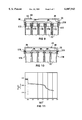
- FIG. 2 shows, from below, a schematic layout, upside down, of the lower side of a flat header panel to which the separator tubes are attached;
- FIG. 3 shows a detail of the flat header panel of FIG. 2, upside down and in sectional side elevation, in the direction of line III--III in FIG. 2;
- FIG. 4 shows a simplified cut-away view, corresponding to that of FIG. 1, of the header and the upper ends of the tubes;
- FIG. 5 shows a schematic sectional side elevation of another electrochemical cell according to the present invention, in the direction of line V--V in FIG. 6;
- FIG. 6 shows, on a reduced scale relative to FIG. 5, a schematic sectional plan view of the tube bundle and tray of the cell of FIG. 5, in the direction of line VI--VI in FIG. 5;
- FIG. 7 shows, for a cell in accordance with the invention as shown in FIG. 1, with a nickel/nickel chloride (NiCl 2 ) cathode, a plot of initial cell internal resistance (m ⁇ ) against cell capacity (Ah) at various temperatures;
- NiCl 2 nickel/nickel chloride
- FIG. 8 shows, for the same cell whose performance is illustrated in FIG. 7, a plot of initial cell internal resistance (m ⁇ )) at the start of each discharge cycle against number of cell charge/discharge cycles at 270° C.;
- FIG. 9 shows a view similar to FIG. 4 of a variation of the construction shown in FIG. 4;
- FIG. 10 shows a view similar to FIG. 4 of a further variation of the construction shown in FIG. 4;
- FIG. 11 shows, for cells different from that whose performance is illustrated in FIGS. 7 and 8, a plot of cell open circuit voltage (V) against time (hours) for the 142nd cycle of the cells when connected in series in a battery;
- FIG. 12 shows, for the same cells and battery whose performance is illustrated in FIG. 11, a plot of both capacity (Ah) and initial cell internal resistance (m ⁇ ) at the start of each discharge cycle against number of cell charge/discharge cycles.
- reference numeral 10 generally designates a high temperature rechargeable electrochemical cell in accordance with the present invention.
- the cell 10 comprises a mild steel housing 12 which comprises a deep-drawn mild steel can 14 having a lid 16 and a flat floor 18 for supporting the cell 10 on a flat upwardly facing support surface in an upright operative attitude.
- the lid 16 has a peripheral rim 19 at its outer periphery whereby it is welded at 20 to a rim at the upper end of the side wall of the can 14.
- the housing 12, and the can 14, are of square plan view outline/horizontal cross-section.
- FIGS. 1 to 4 of the drawings a multiplicity of twenty-five sodium ⁇ "-alumina separator tubes 22 are shown in the can 14, having closed lower ends and open upper ends glass-welded to a flat ⁇ -alumina panel 24 forming the lower wall of a header 26, having an upper wall provided by a further ⁇ -alumina panel 28.
- the lower surface of the panel 24 is shown in FIG. 2, from which it is to be noted that there are twenty-five openings 30 (only two of which are shown in FIG.
- the panel 24 has an upstanding peripheral rim 36 to the upper edge of which the outer periphery of the panel 28 is connected by glass-welding, the upper edge of the rim 36 being received in a peripheral rebate 38 at the outer edge of the panel 28, and glass beading being shown at 39 in the rebate 38 prior to melting for this purpose.
- the panels 24 and 28 together with the rim 36 constitute the header 26 and define therebetween a header space 27.
- a perforated mild steel (optionally nickel instead) shim 40 is coiled as a single layer around each tube 22, resiliently to grip the associated tube 22.
- An ⁇ -alumina collar 42 is glass-welded into a central opening 43 in the panel 28.
- the collar 42 forms a central feedthrough leading through the panel 28 and has flat end surfaces forming, in use, upper- and lower end surfaces thereof, an upper sealing ring 44 and a lower sealing ring 46, each of which are of nickel, being thermocompression bonded respectively to said upper and lower end surfaces.
- the ring 44 has an outer peripheral upstanding rim 45 which is welded to a rim 47 along the periphery of a central opening in the lid 16; and the ring 46 has an inner peripheral upstanding rim 49 which extends upwardly and nests with clearance in the collar 42, adjacent but spaced from the inner curved wall of the collar.
- the upper end of the upstanding rim 49 of the ring 46 is closed off by a metal plug 48 which is welded in position therein and projects upwardly, above the lid 16, to form a cathode terminal 50.
- An anode terminal is welded at 52 to the top of the lid 16; and the collar 42 has a radially outwardly projecting peripheral flange at its upper end which extends over the periphery of the central opening 43 of the panel 28, via which flange the collar 42 is glass-welded to the upper surface of the panel 28.
- the can 14 forms an anode current collector, and a separate cathode current collector is provided for the cell, comprising a flat square nickel current collector plate 54, to the lower surface of which are welded the upper ends of twenty-five downward projections in the form of nickel cathode current collector rods 56, one for each tube 22.
- Each rod 56 projects centrally downwardly into its associated tube 22, the rod 56 having a lower end close to and spaced slightly above the closed lower end of the tube 22.
- the current collector plate 54 has a central opening 57 with an upstanding rim 58.
- the rim 58 nests in the rim 49 of the ring 46, the rim 49 of the ring 46 being sandwiched between the rim 58 and the collar 42, and the rim 58 being sandwiched between the rim 49 and plug 48 the plug 48 being welded into the rim 49 via the rim 58, the rims 49 and 58 being welded together at their upper edges.
- the panel 28 can be placed upside-down, after the collar 42 with its rings 44 and 46 has been glass welded thereto, and after the central rim 58 of the current collector plate 54 has been welded to the upstanding rim 49 of the ring 46.
- the outer upstanding rim 36 of the lower header panel 24 is then glass welded in the associated peripheral rebate 38 of the panel 28, to form the header 26 with the rods 56 projecting out of the openings 30 of the panel 24.
- the open ends of the tubes 24 can be glass-welded in the wide portions 34 of the openings 30 (before or after the shims 40 are wrapped around the associated tubes 22).
- a cathode/solid electrolyte precursor in granular form can be fed via the central feedthrough defined by the collar 28 and via the header space 27 into the tubes 22, or electrolyte granules can be fed to the tubes 22 together with cathode precursor granules, with suitable vibration or tapping, to fill the tubes 22 to a suitable depth (the granules are shown at 60 in FIG.
- reference numeral 110 generally designates another high temperature rechargeable electrochemical cell in accordance with the present invention.
- similar reference numerals have been used in FIGS. 5 and 6 of the drawings to those in FIGS. 1-4 of the drawings, to denote like or similar features.
- a multiplicity of twenty-seven ⁇ "-alumina separator tubes 122 having closed lower ends and open upper ends glass-welded to a flat ⁇ -alumina panel 124 forming the lower wall of a header 126, the upper wall of which is provided by a further ⁇ -alumina panel 128.
- the panel 128 has a downwardly depending peripheral rim 136 to the lower edge of which the outer periphery of the panel 124 is connected by glass-welding.
- the panels 124 and 128 together constitute the header 126 and define therebetween a header space 127.
- the tubes 122 are in side-by-side abutment with one another, being arranged in a hexagonal-close-packed array.
- the tubes 122 are in the form of a bundle and a perforated mild steel (or nickel) shim 140 is shown coiled as a single layer around the bundle, resiliently to grip the bundle and hold its tubes 122 together.
- the lower ends of the tubes 122, and the bundle as a whole, are also held together by a shallow tray 139 having a flat bottom panel 141 and an upstanding rim 145.
- the panel 128 has flat upper and lower surfaces around the feedthrough 143, an upper sealing ring 144 and a lower sealing ring 146, each of which are of nickel, being thermocompression bonded respectively to said upper and lower surfaces around said opening 143.
- the ring 144 has an outer peripheral upstanding rim 147 which is welded to an upstanding rim along the periphery of a central opening in a lid 116; and the ring 146 has an inner peripheral upstanding rim which extends upwardly through the opening 143, adjacent and spaced from the inner curved wall of the opening 143.
- the upper end of the upstanding rim of the ring 146 is welded to the upper end of an upstanding rim 158 along the periphery of a central opening 157 in a current collector plate 154 which is described hereunder.
- the upstanding rim 158 of the central opening 157 of the plate 154 is closed off by a metal plug 148 which is welded in position and projects upwardly, above the lid 116, to form a cathode terminal 150.
- An anode terminal is welded at 152 to the top of the lid 116.
- the can 114 forms an anode current collector, and a separate cathode current collector is provided for the cell, comprising said current collector plate 154 which is of flat square nickel construction and has a central opening as mentioned above, to the lower surface of which are welded the upper ends of twenty-seven downward projections in the form of current collector rods 156, one for each tube 122.
- Each rod 156 projects centrally downwardly into its associated tube 122, the rod 156 having a lower end close to and spaced slightly above the closed lower end of the tube 122.
- the current collector plate 154 has, as mentioned above, a central opening 157 with an upstanding rim 158.
- the rim 158 nests in, and its upper end is welded to, the upper end of the rim of the ring 146, the rim of the ring 146 being located between the rim 158 and the periphery of the opening 143, the plug 148 being welded into the rim 158.
- Electronic connectors 160 are provided to connect the shim 140 to the can 114 (see FIG. 5).
- a multiplicity of thirty-five spaces 162 is defined between the tubes 122 (FIG. 6), and in each of these spaces 162 is provided an aluminium wicking--and anode current-collecting rod 164.
- a corresponding multiplicity of thirty-five openings 166 (FIG.
- each rod 164 is provided through the panel 141 of the tray 139, each rod 164 being associated respectively with each of the openings 166.
- Each rod 164 extends the full length of its space 162 from an upper end at the panel 124 to a lower end in the associated opening 166 in the panel 141.
- the panel 128 can be placed upside-down, after the rings 144 and 146 have been thermocompression-bounded thereto, and after the central rim 158 of the current collector plate 154 has been welded to the upstanding rim of the ring 146.
- the outer rim 136 of the upper header panel 128 is then glass welded to the periphery of the panel 124, to form the header 126 with the rods 156 projecting out of the openings 130 of the panel 124.
- the open ends of the tubes 124 can be glass-welded over the openings 130 (before the shim 140 is wrapped around the bundle of tubes 122).
- the rods 164 can then be inserted in the spaces 162 between the tubes 122 while the closed lower ends of the tubes are inserted into the tray 139 with the lower ends of the rods 164 in the openings 166.
- the inner rim of the lid 116 can then be welded to the upstanding rim 147 of the ring 144 and a rim 119 at the outer periphery of the lid 116 can be welded at 120 to the upper edge or rim of the can 114.
- a cathode/molten salt electrolyte precursor in granular form can be fed via the central feedthrough defined by the opening 143 and rim 158 of the opening 157 in the plate 154, and via the header space 127 into the tubes 122, or electrolyte granules can be fed to the tubes 122 together with cathode precursor granules, with suitable vibration or tapping, to fill the tubes 122 to a suitable depth (the granules are shown at 168 in FIG.
- Each of the cell precursors of the cells 10, 110 is taken in known fashion through a few charge/discharge cycles to commission it and convert it into a cell and to form cathode portions (see 60 in FIG. 1 and 168 in FIG. 5) in the tubes 22, 122, each comprising an electronically conductive porous electrolyte-permeable matrix having a doped sodium aluminium chloride molten salt electrolyte impregnated therein to saturate the matrix, and having a transition metal/transition metal halide active cathode material dispersed in a particulate and/or thin layer form in the porous interior of the matrix.
- Molten sodium will surround the tubes 22, 122 in the anode compartment defined between the tubes 22, 122 and the cans 14, 114.
- Doping of the molten salt electrolyte will typically be with ZrCl 4 or HfCl 4 or R 4 NCl 4 , or a suitable mixture of two or more thereof, to give it a melting point of less than 160° C. and preferably less than 155° C., any ZrCl 4 and HfCl 4 dopants each being used in proportions forming 5-10% by mass of the molten salt electrolyte, and any R 4 NCl 4 being used in a proportion which forms 10-30% by mass of the molten salt electrolyte, the total amount of dopant or dopants added forming less than 30% by mass of the electrolyte.
- a transition metal/transition metal halide active cathode material is dispersed in fine particulate- and/or thin-layer form in the porous interior of the matrix and molten sodium surrounds the tubes 22, 122 in the anode compartment defined between the tubes 22, 122 and can 14, 114.
- Suitable powder mixes for the granules are described in U.S. Pat. No. 4,529,676 (which provides a discharged cathode precursor) and U.S. Pat. No. 4,797,333 (which provides an overdischarged cathode precursor).
- the electrolyte is sodium aluminium chloride (NaAlCl 4 ) in which the molar proportion of AlCl 3 is no greater than that of NaCl at all states of charge of the cell.
- a cell according to FIG. 1 of the drawings has been made from a can 14 having a depth of 140 mm, and a square 50 mm ⁇ 50 mm plan view outline or horizontal cross-section.
- the tubes 22 were 130 mm in length, each having an outer diameter of 9.1 mm and a wall thickness of 0.7 mm, the feedthrough closed by the plug 48 having an inner diameter of 10 mm.
- FIG. 1 is not strictly to scale.
- a substantially similar cell has also been made according to FIG. 5 of the drawings using the same tubes and can as were used for the Example according to FIG. 1.
- a feature of the cells of the present invention is that a high separator area, conducive to high power discharge and rapid charge/discharge rates, can be achieved while, importantly, achieving circular/cylindrical cathode symmetry with narrow cathode dimensions in a direction transverse to the long axes of the tubes 22, 122.
- the cell 10 has twenty-five tubes 22 and the cell 110 twenty-seven tubes 122. Furthermore, the relationship of the combined area of the tubes 22, 122 available for conduction of sodium cations between the anode compartment of the cells 10, 110 and its cathode compartment, as defined by the quotient: ##EQU3## has a value of greater than 2.0 mm -1 .
- the cathode compartment is made up of the interiors of the tubes 22, 122 and the interior or space 27, 127 of the header 26, 126 and the anode compartment is made up of the volume of the interior of the can 14, 114 outside the tubes 22, 122 and header 26, 126.
- a sodium-nickel chloride cell having an open circuit voltage of about 2.58 (the sodium-nickel chloride couple) was constructed in accordance with FIG. 5 of the drawings and having a mass of about 900 g and a theoretical capacity of about 40 Ah.
- the cell was taken through a substantial number of charge/discharge cycles at various temperatures.
- the cell at an 80% depth of discharge, ie after 32 Ah of its capacity had been discharged (at a constant current of 20 Amperes), was subjected to a power pulse of 30 seconds duration at a pre-set maximum current value of about 180 amps or a lower voltage limit of 1.72 volts and at various operating temperatures. Results are set forth in the following table, Table 1, which indicates the discharge cycle number for each pulse, and the cell current in Amperes, voltage in Volts, internal resistance in m ⁇ and power in Watts at the end of each 30-second pulse.
- FIG. 7 is shown a plot of initial cell internal resistance against cell capacity (depth of discharge) for the cell whose results are shown in Table 1, at different temperatures, from fully charged, down to a depth of discharge of about 80% (about 32 Ah).
- a constant current value of 20 amps was used and for charging, IUI charging, with an initial current of 10 amps up to a voltage of 2.67 volts and a final current of 3 amps, was used.
- the temperatures tested were 165° C., 180° C., 200° C., 250° C., 270° C. and 290° C.
- FIG. 8 results are given at 270° C. for the same cell, subjected to the same charging current and voltage and the same discharge current as in FIG. 7.
- Initial cell internal resistance is seen to increase slowly with cell cycle number from 2 m ⁇ at the start of cycling up to about 2.8 m ⁇ at 70-90 cycles, followed by a slight drop to about 2.7 m ⁇ after 100 cycles.
- FIG. 9 instead of having the open upper ends of the tubes 22 received in the lower portions 34 of openings 30 as shown in FIGS. 3 and 4, there are cylindrical downwardly and outwardly projecting peripheral rims or spigots 170 around each opening 30, the openings 30 being of constant diameter and the spigots 170 are received and glass-welded spigot/socket fashion, in the open upper-ends of the tubes 22, which are thickened and reinforced at 172.
- the panel 24 instead of having the panel 24 provided with a rim 36 and the panel 28 without a rim (as in FIGS. 3 and 4), the panel 24 has no rim and the rim 36 is provided on the panel 28, projecting downwardly from the periphery of the panel 28.
- the outer or peripheral edge of the panel 24 is welded in a rebate 174 in the rim 36, whose lower edge encircles the thickened parts at 172 of the outer or peripheral tubes 22.
- FIG. 10 the same reference numerals are used as in FIG. 9, unless otherwise specified.
- the rims or spigots 170 of FIG. 9 are omitted, and the open ends of the tubes 22 are simply butt-welded around the peripheries of the openings 30 to the flat lower surface of the panel 24 by a layer of glass (not shown) on the lower surface of the panel 24.
- the thickened parts at 172 of the upper ends of the tubes 22 of FIG. 9 are omitted and the upper ends of the tubes 22 in FIG. 10 are, instead, of increased internal and external diameter relative to the remainders of the tubes 22 to provide shoulders at 176.
- FIG. 10 also allows, during construction and when the panels 24 and 28 are upside down as shown in FIG. 2, the panel 24 to be received in the rebate 174 in the rim 136, whose lower or free edge, which is directed upwardly in the upside-down condition of the panels 24 and 28, receives and embraces the open ends of the outermost or peripheral tubes 22. This assists in supporting the tubes 22 and in holding them upright, in the correct positions and in close-packed abutment with one another, during glass-welding of the tubes 22 to the panel 24.
- Glass welding for FIGS. 9 and 10 is thus made possible in a single operation, using a glass panel (not shown) in the form of a glass paper, glass mat, or glass sheet formed to have a shape conforming with that of the panel 24 and having openings registering with the openings 30; and inserting this panel between the open ends of the tubes 22 and the panel 24, followed by heating in a furnace to melt the glass.
- a layer of glass paste, applied to the panel 24 between the openings 30 can be used for this purpose, between the tubes 22 and the panel 24.
- This glass panel or paste can indeed supplant the glass beading 39 shown in FIGS. 9 and 10, melting thereof causing it to flow sealingly into the rebate 174.
- each further cell has a mass of 945 g, a name plate capacity of 42 Ah (theoretical capacity of 50 Ah); and nominal cell dimensions of 52 mm ⁇ 52 mm plan view outline and a depth of 180 mm, including its terminals. It used 25 tubes 22 in a square array (see FIGS. 1 and 2).
- FIG. 11 shows discharge curves for the five cells in question, for the 142nd discharge cycle, being plots of cell voltage (V) against time (h). These curves are very close together and overlap, so that they are shown in FIG. 11 as a bundle or envelope having a shaded area.
- the curves initially have a plateau at slightly above 2.5 V for about the first 11/2 hours, representing discharge of nickel chloride, after which, for about an hour, there is an inflection in the curves representing combined nickel chloride/ferrous chloride discharge followed by ferrous chloride discharge. Similar curves for the 15th and 100th cycles were closer together, with smaller bundles or envelopes of lower area, but of substantially the same shape.
- FIG. 12 shows flat curves for both average initial internal resistance (squares) and average capacity (circles) for the five cells of the battery over the full 200 cycles, after slight initial drops in both capacity and internal resistance associated with cell commissioning and running in.
- Table 2 and FIGS. 11 and 12 show excellent cell reproducibility up to 142 cycles and excellent cell stability up to 200 cycles. Furthermore, the pulse power measurements in Table 2, which are done at about two thirds of the open circuit voltage of about 2.58 V, showed that values of above 400 W a cell were attainable at 250° C. or better, and values of above 250 W a cell were achievable at temperatures as low as 170° C.
Abstract
An electrochemical cell comprises a housing defining an interior space, and a separator in the housing dividing said space into an anode compartment and a cathode compartment. A sodium anode is in the anode compartment, a cathode being in the cathode compartment, electrochemically coupled by the separator to the anode. The anode is molten, the separator being a conductor of sodium cations and comprising at least 5 tubes having open and closed ends, the cathode being in the tubes and each tube communicating with a header space in an electronically insulating header. The relationship of the combined area of the tubes available for sodium conduction, and the volume of the interior space, as defined by the quotient: ##EQU1## (in which l is a unit length), has a value of at least 1.0 l-1.
Description
THIS INVENTION relates to a high temperature rechargeable electrochemical cell. More particularly the invention relates to such cell which is suitable for high power applications, and the invention relates to a method of making such cell.
According to the invention there is provided a high temperature rechargeable electrochemical cell which comprises a housing defining an interior space, a ceramic solid electrolyte separator located in the housing and dividing the interior space into an anode compartment and a cathode compartment, an alkali metal active anode material located in the anode compartment, and an active cathode material located in the cathode compartment and electrochemically coupled by the solid electrolyte separator to the active anode material, the cell having an operating temperature at which the active anode material is molten and the solid electrolyte separator being of a material which is a conductor of cations of the active anode material, the solid electrolyte separator comprising a multiplicity of at least 5 ceramic solid electrolyte separator tubes, each tube having an open end and a closed end, the active cathode material being located in the interiors of the tubes and each tube having its open end hermetically sealed to an associated opening leading from the tube into a header space defined by a header comprising electronically insulating ceramic material, the relationship of the combined area of the tubes available for conduction of cations of active anode material between the anode compartment and the cathode compartment, and the volume of the interior space, as defined by the quotient: ##EQU2## (in which l is a unit of length), having a value of at least 1.0 l-1.
The multiplicity of tubes will usually amount to at least 10, with the quotient or said combined area/interior space volume relationship being at least 1.5 l-1. In a preferred embodiment of the invention, the multiplicity of tubes may amount to at least 25, with the quotient or said combined area/interior space volume relationship being at least 2.0 l-1.
Typically, the active anode material will be sodium, the material of the separator being selected from a suitable ceramic solid-electrolyte conductor of sodium cations, such as β-alumina or β"-alumina. For reasons of compatibility of thermal expansion coefficients, during heating and cooling of the cell between its operating temperature and ambient temperature, the header may be of α-alumina, which may be glass-welded to the open ends of the separator tubes.
In a particular embodiment of the invention, each of the tubes may be of the same length as all the other tubes, the cell having an upright operating attitude in which the tubes are suspended by the header from their open upper ends, the associated openings to which the open ends of the tubes are respectively sealed being provided in a flat α-alumina panel forming a lower wall of the header, the cell having a cathode current collector which has a multiplicity of downward projections which project from the header downwardly respectively into each of the tubes, to a position at or adjacent the closed lower end of each tube, the cathode current collector serving to connect in parallel individual amounts of active cathode material located in the respective tubes.
It is expected that the cell will usually either be of the sodium-sulphur/sulphide/polysulphide type or, preferably, of the alkali metal-transition metal/transition metal halide type, such as the sodium-nickel/nickel chloride type, the sodium-iron/ferrous chloride type, or a combination of the sodium-nickel/nickel chloride type and the sodium-iron/ferrous chloride type.
The cell may be of the alkali metal-transition metal/transition metal halide type, having a cathode which comprises an electronically conductive electrolyte-permeable porous matrix having a porous interior in which the active cathode material is dispersed in finely-divided particulate and/or thin-layer solid form, the matrix being impregnated by a molten salt electrolyte which saturates the porous interior of the matrix, the downward projections of the cathode current collector being electronically connected to the matrix. In particular the cells may have a cathode in which there are nickel and iron in a mass ratio of 88:12-80:20, preferably 86:14-82:18, eg 84:16. Usually, but not necessarily, nickel and iron will be essentially the only transition metals present in the cathode.
Preferably the molten salt electrolyte has a melting point below 170° C., more preferably bellow 160° C. The molten salt electrolyte may be a sodium aluminium halide electrolyte, in which there are essentially equal amounts of alkali metal halide and aluminium halide, the aluminium halide:alkali metal halide ratio being at most 1:1.
In particular, the molten salt electrolyte may be a sodium aluminium chloride electrolyte doped by at least one dopant which acts to lower its melting point but which is otherwise inert or at least compatible with the cell cathode environment. The cell may have a dopant content in total forming 1-30% by mass of the molten salt electrolyte, typically 3-20% by mass thereof.
Suitable dopants include zirconium tetrachloride (ZrCl4), hafnium tetrachloride (HfCl4) and suitable quaternary ammonium halide salts, such as the chloride salts, of formula R4 NAlHal4, wherein each R is a hydrocarbon group such as an alkyl group, the R groups being the same or different from one another, and each Hal is a halide anion, which anions may be the same or different from one another, but conveniently all being Cl anions. Any ZrCl4 and the HfCl4 may each be present in proportions which form 5-10% by mass of the molten salt electrolyte; and any R4 NAlHal4 may be present in a proportion which forms 10-30% by mass of the molten salt electrolyte.
Thus, each dopant may be selected from the group consisting of zirconium tetrachloride, hafnium tetrachloride, quaternary ammonium halide salts, and any mixtures thereof, any said tetrahalide salts forming in total 5-10% by mass of the molten salt electrolyte and any said ammonium halide salts forming in total 10-30% by mass of the molten salt electrolyte.
The housing may be a metal housing, such as a mild steel housing, the housing forming an anode current collector and an anode cell terminal being provided on the housing, the cathode current collector being connected to a cathode terminal which projects outwardly from the housing and is electronically insulated from the housing.
For close packing of cells alongside one another the cell may have a horizontal cross-section or plan view outline which is selected to permit a plurality of said cells to be close-packed alongside one another, in a close-packing arrangement. Conveniently, the cell may have a horizontal cross-section or plan view outline which is square, hexagonal, rectangular or triangular, so that a plurality of the cells can be close-packed alongside one another, in a hexagonal- or square close packing arrangement.
The tubes may be arranged so that their open upper ends, sealed to the header, which may, for example, comprise a flat α-alumina header panel, are in a grid arrangement selected from hexagonal grid arrangements and square grid arrangements.
Each tube may have an outer surface which is enclosed by a thin-walled shim, which may be perforated, coiled around the tube and forming a wick for wicking the molten anode material upwardly over and in contact with the outer surface of the tube.
The tubes may be arranged in a close-packed arrangement, the tubes defining a multiplicity of at least 6 longitudinally extending spaces therebetween and the cell comprising a multiplicity of anode current collectors in the form of electronically conductive rods located respectively in the spaces between the close-packed tubes.
While the arrangement may be a cubic-close packed arrangement, it is preferably a hexagonal-close packed arrangement. The spaces will be bounded, in the case of cubic-close packing, by four tubes and will be bounded, in the case of hexagonal-close packing, by three tubes.
Each anode current collector rod may fill the associated longitudinally extending space sufficiently to act as a wick for wicking molten anode material upwardly in said associated longitudinally extending space. Thus, the rods have a dual function, namely wicking molten anode material along the spaces between the tubes, and anode current collecting.
Preferably, each tube may be substantially in side-by-side contact with all the tubes adjacent or surrounding it. Thus, each rod may have a diameter such that it is substantially in contact, along its full length, with the tubes adjacent or surrounding it, although it need not be in contact with all the tubes along its full length, provided that it is close enough thereto to provide for adequate wicking of molten alkali metal anode material along the length of said space.
Preferably, each rod may be of aluminium and may extend along the associated longitudinally extending space for the full length of said space.
The closed ends of the tubes, and the tubes as a whole, may be bundled together, and may be held in close-packed abutment with one another, by a cup-shaped tray, typically a shallow aluminium or mild steel metal tray, having a bottom panel provided with an upstanding peripheral rim which embraces the outermost peripheral tubes of the bundle, the bottom panel of the tray optionally having a multiplicity of openings therethrough, respectively in register with the anode current collecting rods, each rod extending downwardly, from an upper end at or adjacent the header, to a lower end located in or adjacent the associated opening in the bottom panel of the tray. The bottom panel may be flat.
According to another aspect of the invention, there is provided a method of making a cell of the type described above, which comprises forming the tubes and parts of the header respectively from sintered ceramic solid electrolyte powder material and from sintered ceramic electronically insulating powder material, hermetically sealing the parts of the header together to form the header and hermetically sealing the open end of each tube to an associated opening into the header, the header being formed so that it has a feedthrough which, in an operative upright attitude of the tubes, leads into the top of the header, the method further comprising feeding the active cathode material or a precursor thereof into the open ends of the tubes via the feedthrough and via the header space in the header, after the tubes have been sealed to the header.
The active cathode material or its precursor is conveniently in the form of granules, which can be relatively free-flowing compared with powders, and the granules may be fed into the header space before or after the tubes and header have been inserted into the housing, which is conveniently a deep-drawn open-topped can having a lid which will be hermetically sealed in place after the tubes and header are in position in the can. Conveniently the cathode current collector is located in place in the header before the header parts are sealed together, so that it projects out of the openings in the header to which the tubes are sealed; and the shim wick may be wrapped around the bundle of tubes after the tubes are sealed to the header. The sealing together of the parts of the header, and the sealing of the tubes in the header, may be glass-welding. The tubes may be bundled together by inserting their lower closed ends downwardly into the tray and the anode current-collecting rods may be inserted into the spaces between the tubes after the tubes have been sealed to the header, and before or after the tubes have been inserted into the tray.
The feedthrough may be defined by a part of the header which is in the form of a collar, a pair of metal sealing rings respectively being sealed to the opposite ends of the collar by thermocompression bonding, one of the sealing rings being metal-welded to the lid of the housing and the lid in turn being metal-welded to the open upper end of the can, a metal plug, which may form the cathode terminal, in turn being welded into the other of the sealing rings, to close off the feedthrough, the cathode current collector being welded to said plug, and said plug and the associated sealing ring being electronically insulated and isolated from the other sealing ring and the associated can.
The invention will now be described, by way of non-limiting illustrative example, with reference to the accompanying diagrammatic drawings, in which:
FIG. 1 shows a schematic sectional side elevation of an electrochemical cell according to the present invention;
FIG. 2 shows, from below, a schematic layout, upside down, of the lower side of a flat header panel to which the separator tubes are attached;
FIG. 3 shows a detail of the flat header panel of FIG. 2, upside down and in sectional side elevation, in the direction of line III--III in FIG. 2;
FIG. 4 shows a simplified cut-away view, corresponding to that of FIG. 1, of the header and the upper ends of the tubes;
FIG. 5 shows a schematic sectional side elevation of another electrochemical cell according to the present invention, in the direction of line V--V in FIG. 6;
FIG. 6 shows, on a reduced scale relative to FIG. 5, a schematic sectional plan view of the tube bundle and tray of the cell of FIG. 5, in the direction of line VI--VI in FIG. 5;
FIG. 7 shows, for a cell in accordance with the invention as shown in FIG. 1, with a nickel/nickel chloride (NiCl2) cathode, a plot of initial cell internal resistance (mΩ) against cell capacity (Ah) at various temperatures;
FIG. 8 shows, for the same cell whose performance is illustrated in FIG. 7, a plot of initial cell internal resistance (mΩ)) at the start of each discharge cycle against number of cell charge/discharge cycles at 270° C.;
FIG. 9 shows a view similar to FIG. 4 of a variation of the construction shown in FIG. 4;
FIG. 10 shows a view similar to FIG. 4 of a further variation of the construction shown in FIG. 4;
FIG. 11 shows, for cells different from that whose performance is illustrated in FIGS. 7 and 8, a plot of cell open circuit voltage (V) against time (hours) for the 142nd cycle of the cells when connected in series in a battery; and
FIG. 12 shows, for the same cells and battery whose performance is illustrated in FIG. 11, a plot of both capacity (Ah) and initial cell internal resistance (mΩ) at the start of each discharge cycle against number of cell charge/discharge cycles.
In FIG. 1 of the drawings, reference numeral 10 generally designates a high temperature rechargeable electrochemical cell in accordance with the present invention. The cell 10 comprises a mild steel housing 12 which comprises a deep-drawn mild steel can 14 having a lid 16 and a flat floor 18 for supporting the cell 10 on a flat upwardly facing support surface in an upright operative attitude. The lid 16 has a peripheral rim 19 at its outer periphery whereby it is welded at 20 to a rim at the upper end of the side wall of the can 14. The housing 12, and the can 14, are of square plan view outline/horizontal cross-section.
In FIGS. 1 to 4 of the drawings, a multiplicity of twenty-five sodium β"-alumina separator tubes 22 are shown in the can 14, having closed lower ends and open upper ends glass-welded to a flat α-alumina panel 24 forming the lower wall of a header 26, having an upper wall provided by a further α-alumina panel 28. The lower surface of the panel 24 is shown in FIG. 2, from which it is to be noted that there are twenty-five openings 30 (only two of which are shown in FIG. 3) through the panel 24, each having a narrow upper portion 32 of a diameter corresponding to the inner diameter of the tubes 22 and each having a wide lower portion 34 of a diameter corresponding to the outer diameter of the tubes 22 and in which the open upper ends of the tubes 22 are received and glass-welded (see particularly FIG. 1). The panel 24 has an upstanding peripheral rim 36 to the upper edge of which the outer periphery of the panel 28 is connected by glass-welding, the upper edge of the rim 36 being received in a peripheral rebate 38 at the outer edge of the panel 28, and glass beading being shown at 39 in the rebate 38 prior to melting for this purpose. The panels 24 and 28 together with the rim 36 constitute the header 26 and define therebetween a header space 27. A perforated mild steel (optionally nickel instead) shim 40 is coiled as a single layer around each tube 22, resiliently to grip the associated tube 22.
An α-alumina collar 42 is glass-welded into a central opening 43 in the panel 28. The collar 42 forms a central feedthrough leading through the panel 28 and has flat end surfaces forming, in use, upper- and lower end surfaces thereof, an upper sealing ring 44 and a lower sealing ring 46, each of which are of nickel, being thermocompression bonded respectively to said upper and lower end surfaces. The ring 44 has an outer peripheral upstanding rim 45 which is welded to a rim 47 along the periphery of a central opening in the lid 16; and the ring 46 has an inner peripheral upstanding rim 49 which extends upwardly and nests with clearance in the collar 42, adjacent but spaced from the inner curved wall of the collar. The upper end of the upstanding rim 49 of the ring 46 is closed off by a metal plug 48 which is welded in position therein and projects upwardly, above the lid 16, to form a cathode terminal 50. An anode terminal is welded at 52 to the top of the lid 16; and the collar 42 has a radially outwardly projecting peripheral flange at its upper end which extends over the periphery of the central opening 43 of the panel 28, via which flange the collar 42 is glass-welded to the upper surface of the panel 28. The can 14 forms an anode current collector, and a separate cathode current collector is provided for the cell, comprising a flat square nickel current collector plate 54, to the lower surface of which are welded the upper ends of twenty-five downward projections in the form of nickel cathode current collector rods 56, one for each tube 22. Each rod 56 projects centrally downwardly into its associated tube 22, the rod 56 having a lower end close to and spaced slightly above the closed lower end of the tube 22. The current collector plate 54 has a central opening 57 with an upstanding rim 58. The rim 58 nests in the rim 49 of the ring 46, the rim 49 of the ring 46 being sandwiched between the rim 58 and the collar 42, and the rim 58 being sandwiched between the rim 49 and plug 48 the plug 48 being welded into the rim 49 via the rim 58, the rims 49 and 58 being welded together at their upper edges.
To make the cell 10 the panel 28 can be placed upside-down, after the collar 42 with its rings 44 and 46 has been glass welded thereto, and after the central rim 58 of the current collector plate 54 has been welded to the upstanding rim 49 of the ring 46. The outer upstanding rim 36 of the lower header panel 24 is then glass welded in the associated peripheral rebate 38 of the panel 28, to form the header 26 with the rods 56 projecting out of the openings 30 of the panel 24. After this, the open ends of the tubes 24 can be glass-welded in the wide portions 34 of the openings 30 (before or after the shims 40 are wrapped around the associated tubes 22). The rim 47 of the lid 16 can then be welded to the upstanding rim 45 of the ring 44 and the rim 19 at the outer periphery of the lid 16 can then be welded at 20 to the upper edge or rim of the can 14. At this stage a cathode/solid electrolyte precursor in granular form can be fed via the central feedthrough defined by the collar 28 and via the header space 27 into the tubes 22, or electrolyte granules can be fed to the tubes 22 together with cathode precursor granules, with suitable vibration or tapping, to fill the tubes 22 to a suitable depth (the granules are shown at 60 in FIG. 1), to form a cell precursor, a small amount of sodium optionally being charged into the bottom of the can 14, sufficient when molten to be wicked by the shims 40 into contact with the lower ends of the tubes 22, the shims 40 in fact nearly touching the floor 18 of the can 16.
Referring now to FIGS. 5 and 6 of the drawings, reference numeral 110 generally designates another high temperature rechargeable electrochemical cell in accordance with the present invention. For ease of reference, similar reference numerals have been used in FIGS. 5 and 6 of the drawings to those in FIGS. 1-4 of the drawings, to denote like or similar features.
In the can 114 are shown a multiplicity of twenty-seven β"-alumina separator tubes 122, having closed lower ends and open upper ends glass-welded to a flat α-alumina panel 124 forming the lower wall of a header 126, the upper wall of which is provided by a further α-alumina panel 128. There are twenty-seven openings 130 through the panel 124, over which the open upper ends of the tubes 122 are glass-welded (see FIG. 5). The panel 128 has a downwardly depending peripheral rim 136 to the lower edge of which the outer periphery of the panel 124 is connected by glass-welding. The panels 124 and 128 together constitute the header 126 and define therebetween a header space 127. The tubes 122 are in side-by-side abutment with one another, being arranged in a hexagonal-close-packed array. The tubes 122 are in the form of a bundle and a perforated mild steel (or nickel) shim 140 is shown coiled as a single layer around the bundle, resiliently to grip the bundle and hold its tubes 122 together. The lower ends of the tubes 122, and the bundle as a whole, are also held together by a shallow tray 139 having a flat bottom panel 141 and an upstanding rim 145.
There is a central opening 143 in the panel 128, which forms a central feedthrough through the panel 128. The panel 128 has flat upper and lower surfaces around the feedthrough 143, an upper sealing ring 144 and a lower sealing ring 146, each of which are of nickel, being thermocompression bonded respectively to said upper and lower surfaces around said opening 143. The ring 144 has an outer peripheral upstanding rim 147 which is welded to an upstanding rim along the periphery of a central opening in a lid 116; and the ring 146 has an inner peripheral upstanding rim which extends upwardly through the opening 143, adjacent and spaced from the inner curved wall of the opening 143. The upper end of the upstanding rim of the ring 146 is welded to the upper end of an upstanding rim 158 along the periphery of a central opening 157 in a current collector plate 154 which is described hereunder. The upstanding rim 158 of the central opening 157 of the plate 154 is closed off by a metal plug 148 which is welded in position and projects upwardly, above the lid 116, to form a cathode terminal 150. An anode terminal is welded at 152 to the top of the lid 116. The can 114 forms an anode current collector, and a separate cathode current collector is provided for the cell, comprising said current collector plate 154 which is of flat square nickel construction and has a central opening as mentioned above, to the lower surface of which are welded the upper ends of twenty-seven downward projections in the form of current collector rods 156, one for each tube 122. Each rod 156 projects centrally downwardly into its associated tube 122, the rod 156 having a lower end close to and spaced slightly above the closed lower end of the tube 122. The current collector plate 154 has, as mentioned above, a central opening 157 with an upstanding rim 158. The rim 158 nests in, and its upper end is welded to, the upper end of the rim of the ring 146, the rim of the ring 146 being located between the rim 158 and the periphery of the opening 143, the plug 148 being welded into the rim 158. Electronic connectors 160 are provided to connect the shim 140 to the can 114 (see FIG. 5). A multiplicity of thirty-five spaces 162 is defined between the tubes 122 (FIG. 6), and in each of these spaces 162 is provided an aluminium wicking--and anode current-collecting rod 164. A corresponding multiplicity of thirty-five openings 166 (FIG. 5) is provided through the panel 141 of the tray 139, each rod 164 being associated respectively with each of the openings 166. Each rod 164 extends the full length of its space 162 from an upper end at the panel 124 to a lower end in the associated opening 166 in the panel 141.
To make the cell 110 the panel 128 can be placed upside-down, after the rings 144 and 146 have been thermocompression-bounded thereto, and after the central rim 158 of the current collector plate 154 has been welded to the upstanding rim of the ring 146. The outer rim 136 of the upper header panel 128 is then glass welded to the periphery of the panel 124, to form the header 126 with the rods 156 projecting out of the openings 130 of the panel 124. After this the open ends of the tubes 124 can be glass-welded over the openings 130 (before the shim 140 is wrapped around the bundle of tubes 122). The rods 164 can then be inserted in the spaces 162 between the tubes 122 while the closed lower ends of the tubes are inserted into the tray 139 with the lower ends of the rods 164 in the openings 166. The inner rim of the lid 116 can then be welded to the upstanding rim 147 of the ring 144 and a rim 119 at the outer periphery of the lid 116 can be welded at 120 to the upper edge or rim of the can 114. At this stage a cathode/molten salt electrolyte precursor in granular form can be fed via the central feedthrough defined by the opening 143 and rim 158 of the opening 157 in the plate 154, and via the header space 127 into the tubes 122, or electrolyte granules can be fed to the tubes 122 together with cathode precursor granules, with suitable vibration or tapping, to fill the tubes 122 to a suitable depth (the granules are shown at 168 in FIG. 5), to form a cell precursor, a small amount of sodium optionally being charged into the bottom of the can 114, sufficient when molten to be wicked by the rods 164 and shim 140 into contact with the tubes 122, the rods 164 in fact nearly touching the floor 118 of the can 116.
Each of the cell precursors of the cells 10, 110 is taken in known fashion through a few charge/discharge cycles to commission it and convert it into a cell and to form cathode portions (see 60 in FIG. 1 and 168 in FIG. 5) in the tubes 22, 122, each comprising an electronically conductive porous electrolyte-permeable matrix having a doped sodium aluminium chloride molten salt electrolyte impregnated therein to saturate the matrix, and having a transition metal/transition metal halide active cathode material dispersed in a particulate and/or thin layer form in the porous interior of the matrix. Molten sodium will surround the tubes 22, 122 in the anode compartment defined between the tubes 22, 122 and the cans 14, 114.
Doping of the molten salt electrolyte will typically be with ZrCl4 or HfCl4 or R4 NCl4, or a suitable mixture of two or more thereof, to give it a melting point of less than 160° C. and preferably less than 155° C., any ZrCl4 and HfCl4 dopants each being used in proportions forming 5-10% by mass of the molten salt electrolyte, and any R4 NCl4 being used in a proportion which forms 10-30% by mass of the molten salt electrolyte, the total amount of dopant or dopants added forming less than 30% by mass of the electrolyte. A transition metal/transition metal halide active cathode material is dispersed in fine particulate- and/or thin-layer form in the porous interior of the matrix and molten sodium surrounds the tubes 22, 122 in the anode compartment defined between the tubes 22, 122 and can 14, 114. Suitable powder mixes for the granules are described in U.S. Pat. No. 4,529,676 (which provides a discharged cathode precursor) and U.S. Pat. No. 4,797,333 (which provides an overdischarged cathode precursor).
The electrolyte is sodium aluminium chloride (NaAlCl4) in which the molar proportion of AlCl3 is no greater than that of NaCl at all states of charge of the cell.
For example, a cell according to FIG. 1 of the drawings has been made from a can 14 having a depth of 140 mm, and a square 50 mm×50 mm plan view outline or horizontal cross-section. In this example the tubes 22 were 130 mm in length, each having an outer diameter of 9.1 mm and a wall thickness of 0.7 mm, the feedthrough closed by the plug 48 having an inner diameter of 10 mm. In this regard it should be noted that FIG. 1 is not strictly to scale. A substantially similar cell has also been made according to FIG. 5 of the drawings using the same tubes and can as were used for the Example according to FIG. 1.
A feature of the cells of the present invention is that a high separator area, conducive to high power discharge and rapid charge/discharge rates, can be achieved while, importantly, achieving circular/cylindrical cathode symmetry with narrow cathode dimensions in a direction transverse to the long axes of the tubes 22, 122.
As mentioned above, the cell 10 has twenty-five tubes 22 and the cell 110 twenty-seven tubes 122. Furthermore, the relationship of the combined area of the tubes 22, 122 available for conduction of sodium cations between the anode compartment of the cells 10, 110 and its cathode compartment, as defined by the quotient: ##EQU3## has a value of greater than 2.0 mm-1. In this regard the cathode compartment is made up of the interiors of the tubes 22, 122 and the interior or space 27, 127 of the header 26, 126 and the anode compartment is made up of the volume of the interior of the can 14, 114 outside the tubes 22, 122 and header 26, 126.
Preliminary tests have been conducted by the Applicant on cells according to the invention, which show substantial promise for reversible high-power operation.
Thus, a sodium-nickel chloride cell having an open circuit voltage of about 2.58 (the sodium-nickel chloride couple) was constructed in accordance with FIG. 5 of the drawings and having a mass of about 900 g and a theoretical capacity of about 40 Ah. The cell was taken through a substantial number of charge/discharge cycles at various temperatures. In accordance with one of the tests the cell, at an 80% depth of discharge, ie after 32 Ah of its capacity had been discharged (at a constant current of 20 Amperes), was subjected to a power pulse of 30 seconds duration at a pre-set maximum current value of about 180 amps or a lower voltage limit of 1.72 volts and at various operating temperatures. Results are set forth in the following table, Table 1, which indicates the discharge cycle number for each pulse, and the cell current in Amperes, voltage in Volts, internal resistance in mΩ and power in Watts at the end of each 30-second pulse.
              TABLE 1
______________________________________
Cell Characteristics at end of 30 Second Power Pulse at Maximum Current
  Cycle  Temperature Current
                           Voltage Resistance
                                          Power
  No. (° C.) (A) (V) (mΩ) (W)
______________________________________
4    290         178.7   1.99    3.3    355.6
  5 270 180.4 1.94 3.5 350.0
  6 250 180.6 1.91 3.7 345.0
  7 200 174.8 1.72 4.9 300.6
  8 180 139.0 1.72 6.2 239.0
  9 165 91.2 1.72 9.5 156.8
  83 270 179.6 1.95 3.5 350.2
______________________________________
It is to be noted from Table 1 that the cell delivered substantially the same power at 270° C. after the 83rd cycle as after the 5th cycle. As expected, internal resistance was sensitive to temperature changes. However, virtually no improvement was seen above 250° C. as the cell hardware internal resistance, as contrasted with the internal resistance arising from the molten salt electrolyte, became limiting at that temperature. Power was nevertheless adequate, even at 165° C., as shown in Table 1.
For the 40 Ah cell whose results are shown in Table 1, the cell characteristics are further shown in FIGS. 7 and 8.
In FIG. 7 is shown a plot of initial cell internal resistance against cell capacity (depth of discharge) for the cell whose results are shown in Table 1, at different temperatures, from fully charged, down to a depth of discharge of about 80% (about 32 Ah). For discharging a constant current value of 20 amps was used and for charging, IUI charging, with an initial current of 10 amps up to a voltage of 2.67 volts and a final current of 3 amps, was used. The temperatures tested were 165° C., 180° C., 200° C., 250° C., 270° C. and 290° C.
Turning to FIG. 8 results are given at 270° C. for the same cell, subjected to the same charging current and voltage and the same discharge current as in FIG. 7. Initial cell internal resistance is seen to increase slowly with cell cycle number from 2 mΩ at the start of cycling up to about 2.8 mΩ at 70-90 cycles, followed by a slight drop to about 2.7 mΩ after 100 cycles.
The results set forth in Table 1 and in FIGS. 7-8 demonstrate that, with the cell geometry of the present invention, as illustrated, acceptably high power can be obtained at temperatures as low as 165° C. These results show that, depending on the availability of suitable low-melting electrolytes based, for example, on NaAlCl4, acceptable power may be available in terms of the present invention, at temperatures as low as 150° C. or even 120° C.
In FIG. 9, instead of having the open upper ends of the tubes 22 received in the lower portions 34 of openings 30 as shown in FIGS. 3 and 4, there are cylindrical downwardly and outwardly projecting peripheral rims or spigots 170 around each opening 30, the openings 30 being of constant diameter and the spigots 170 are received and glass-welded spigot/socket fashion, in the open upper-ends of the tubes 22, which are thickened and reinforced at 172. Furthermore, instead of having the panel 24 provided with a rim 36 and the panel 28 without a rim (as in FIGS. 3 and 4), the panel 24 has no rim and the rim 36 is provided on the panel 28, projecting downwardly from the periphery of the panel 28. The outer or peripheral edge of the panel 24 is welded in a rebate 174 in the rim 36, whose lower edge encircles the thickened parts at 172 of the outer or peripheral tubes 22.
In FIG. 10, the same reference numerals are used as in FIG. 9, unless otherwise specified. In FIG. 10 the rims or spigots 170 of FIG. 9 are omitted, and the open ends of the tubes 22 are simply butt-welded around the peripheries of the openings 30 to the flat lower surface of the panel 24 by a layer of glass (not shown) on the lower surface of the panel 24. Furthermore, the thickened parts at 172 of the upper ends of the tubes 22 of FIG. 9 are omitted and the upper ends of the tubes 22 in FIG. 10 are, instead, of increased internal and external diameter relative to the remainders of the tubes 22 to provide shoulders at 176. This feature allows the upper ends of the tubes 22 to be closed-packed in abutment with one another, but provides for somewhat enlarged spaces 162 (see FIG. 6) between the tubes 22 for receiving the rods 164 (see FIG. 6), and the same consideration indeed applies also to the construction of FIG. 9.
The construction shown in FIG. 10 also allows, during construction and when the panels 24 and 28 are upside down as shown in FIG. 2, the panel 24 to be received in the rebate 174 in the rim 136, whose lower or free edge, which is directed upwardly in the upside-down condition of the panels 24 and 28, receives and embraces the open ends of the outermost or peripheral tubes 22. This assists in supporting the tubes 22 and in holding them upright, in the correct positions and in close-packed abutment with one another, during glass-welding of the tubes 22 to the panel 24.
Glass welding for FIGS. 9 and 10 is thus made possible in a single operation, using a glass panel (not shown) in the form of a glass paper, glass mat, or glass sheet formed to have a shape conforming with that of the panel 24 and having openings registering with the openings 30; and inserting this panel between the open ends of the tubes 22 and the panel 24, followed by heating in a furnace to melt the glass. Instead, a layer of glass paste, applied to the panel 24 between the openings 30 can be used for this purpose, between the tubes 22 and the panel 24. This glass panel or paste can indeed supplant the glass beading 39 shown in FIGS. 9 and 10, melting thereof causing it to flow sealingly into the rebate 174.
Further cells were made in accordance with FIG. 1 and in accordance with the invention, essentially similar to the sodium-nickel/nickel chloride cell described above. However, whereas the cell described above had nickel as substantially the only electrochemically active cathode transition metal, any iron therein being associated merely with sulphur doping of the cathode, as ferrous sulphide and contributing negligibly to cell capacity, each further cell had a substantial amount of electrochemically active iron in its cathode, together with nickel, this iron contributing materially to cell capacity. Thus, in these further cells, 15% by mass of the nickel of the cathode of the sodium-nickel/nickel chloride cell described above was replaced by iron, the cathode precursor granules used in making the cathode containing, mixed together and dispersed homogeneously with each other, nickel powder and iron powder in an 85:15 mass ratio. Each further cell has a mass of 945 g, a name plate capacity of 42 Ah (theoretical capacity of 50 Ah); and nominal cell dimensions of 52 mm×52 mm plan view outline and a depth of 180 mm, including its terminals. It used 25 tubes 22 in a square array (see FIGS. 1 and 2).
These further cells were connected in series in batteries and were subjected to tests wherein the batteries were put through charge/discharge cycles at various temperatures, usually 270° C. Batteries of two, four or five cells were employed. At various depths of discharge, after various proportions (32 Ah, 34 Ah and 40 Ah) of capacity had been discharged (at a constant current of 20 Amperes), the cells in the batteries were subjected to power pulses of 30 seconds duration. Results are set forth in the following table, Table 2, which is similar to Table 1, but omits cell internal resistance while indicating also the number of cells in the battery and the depth of discharge in Ah at which the pulse was started.
              TABLE 2
______________________________________
       Depth of
  Number Discharge
  of Cells at Start
  in of Pulse Cycle Temperature Current Voltage Power
  Battery (Ah) No (° C.) (A) (V) (W)
______________________________________
2      32       8      270     241.1 1.745 420.7
  2 32 50 270 247.2 1.745 431.3
  2 34 152 270 242.7 1.720 417.4
  2 34 204 270 239.1 1.720 411.3
  5 34 30 250 232.8 1.720 400.4
  4 34 20 187 181.9 1.720 312.8
  4 34 24 175 161.6 1.720 278.0
  2 40 8 270 218.0 1.745 380.4
______________________________________
The battery of five cells was taken through a total of over 200 charge/discharge cycles at a constant discharge current of 16 A to a depth of discharge of 42 Ah and with IUI charging with an initial current of 10 A up to a voltage of 2.67 V and a final current of 1 A. FIG. 11 shows discharge curves for the five cells in question, for the 142nd discharge cycle, being plots of cell voltage (V) against time (h). These curves are very close together and overlap, so that they are shown in FIG. 11 as a bundle or envelope having a shaded area. The curves initially have a plateau at slightly above 2.5 V for about the first 11/2 hours, representing discharge of nickel chloride, after which, for about an hour, there is an inflection in the curves representing combined nickel chloride/ferrous chloride discharge followed by ferrous chloride discharge. Similar curves for the 15th and 100th cycles were closer together, with smaller bundles or envelopes of lower area, but of substantially the same shape.
FIG. 12 shows flat curves for both average initial internal resistance (squares) and average capacity (circles) for the five cells of the battery over the full 200 cycles, after slight initial drops in both capacity and internal resistance associated with cell commissioning and running in.
The results in Table 2 and FIGS. 11 and 12 show excellent cell reproducibility up to 142 cycles and excellent cell stability up to 200 cycles. Furthermore, the pulse power measurements in Table 2, which are done at about two thirds of the open circuit voltage of about 2.58 V, showed that values of above 400 W a cell were attainable at 250° C. or better, and values of above 250 W a cell were achievable at temperatures as low as 170° C.
Claims (19)
1. A high temperature rechargeable electrochemical cell which comprises a housing defining an interior space, a ceramic solid electrolyte separator located in the housing and dividing the interior space into an anode compartment and a cathode compartment, an alkali metal active anode material located in the anode compartment, and an active cathode material located in the cathode compartment and electrochemically coupled by the solid electrolyte separator to the active anode material, the cell having an operating temperature at which the active anode material is molten and the solid electrolyte separator being of a material which is a conductor of cations of the active anode material, the solid electrolyte separator comprising a multiplicity of at least 5 ceramic solid electrolyte separator tubes, each tube having an open end and a closed end, the active cathode material being located in the interiors of the tubes and each tube having its open end hermetically sealed to an associated opening leading from the tube into a header space defined by a header comprising electronically insulating ceramic material, the relationship of the combined area of the tubes available for conduction of cations of active anode material between the anode compartment and the cathode compartment, and the volume of the interior space, as defined by the quotient: ##EQU4## (in which l is a unit of length), having a value of at least 1.0 l-1, the tubes being arranged side-by-side to define a multiplicity of at least 6 longitudinally extending spaces therebetween and the cell comprising a multiplicity of anode current collectors in the form of electronically conductive rods located respectively in said spaces defined between the tubes.
2. A cell as claimed in claim 1, in which the multiplicity of tubes amounts to at least 10, with the quotient being at least 1.5 l-1.
3. A cell as claimed in claim 2, in which the multiplicity of tubes amounts to at least 25, with the quotient being at least 2.0 l-1.
4. A cell as claimed in claim 1, in which the active anode material is sodium, the material of the separator being selected from β-alumina and β"-alumina.
5. A cell as claimed in claim 1, in which each of the tubes is of the same length as all the other tubes, the cell having an upright operating attitude in which the tubes are suspended by the header from their open upper ends, the associated openings to which the open ends of the tubes are respectively sealed being provided in a flat α-alumina panel forming a lower wall of the header, the cell having a cathode current collector which has a multiplicity of downward projections which project from the header downwardly respectively into each of the tubes, to a position at or adjacent the closed lower end of each tube, the cathode current collector serving to connect in parallel individual amounts of active cathode material located in the respective tubes.
6. A cell as claimed in claim 5, in which the cell is of an alkali metal-transition metal/transition metal halide type, having a cathode which comprises an electronically conductive electrolyte-permeable porous matrix having a porous interior in which the active cathode material is dispersed in finely-divided particulate and/or thin-layer solid form, the matrix being impregnated by a molten salt electrolyte which saturates the porous interior of the matrix, the downward projections of the cathode current collector being electronically connected to the matrix.
7. A cell as claimed in claim 6, which has a cathode in which there are nickel and iron in a mass ratio of 88:12-80:20.
8. A cell as claimed in claim 6, in which the molten salt electrolyte is a sodium aluminium chloride electrolyte doped by at least one dopant which acts to lower its melting point but which is otherwise compatible with the cell cathode environment, the cell having a dopant content in total forming 1-30% by mass of the molten salt electrolyte.
9. A cell as claimed in claim 8, in which each dopant is selected from the group consisting of zirconium tetrachloride, hafnium tetrachloride, quaternary ammonium halide salts, and any mixtures thereof, any said tetrahalide salts forming in total 5-10% by mass of the molten salt electrolyte and any said ammonium halide salts forming in total 10-30% by mass of the molten salt electrolyte.
10. A cell as claimed in claim 5, in which the housing is a metal housing, the housing forming an anode current collector and an anode cell terminal being provided on the housing, the cathode current collector being connected to a cathode terminal which projects outwardly from the housing and is electronically insulated from the housing.
11. A cell as claimed in claim 1, in which the cell has a horizontal cross-section or plan view outline which is selected to permit a plurality of said cells to be close-packed alongside one another, in a close-packing arrangement.
12. A cell as claimed in claim 1, in which the tubes are arranged so that their open upper ends, sealed to the header, are in a grid arrangement selected from hexagonal grid arrangements and square grid arrangements.
13. A cell as claimed in claim 1, in which each tube has an outer surface which is enclosed by a thin-walled shim coiled around the tube and forming a wick for wicking the molten anode material upwardly over and in contact with the outer surface of the tube.
14. A cell as claimed in claim 1, in which the tubes are arranged in a close-packed arrangement.
15. A cell as claimed in claim 1, in which each anode current collector rod fills the associated longitudinally extending space sufficiently to act as a wick for wicking molten anode material upwardly in said associated longitudinally extending space.
16. A cell as claimed in claim 1, in which each rod is of aluminium, each rod extending along the associated longitudinally extending space for the full length of said space.
17. A cell as claimed in claim 14, in which the closed ends of the tubes, and the tubes as a whole, are bundled together, and are held in close-packed abutment with one another, by a cup-shaped tray having a bottom panel provided with an upstanding peripheral rim which embraces the outermost peripheral tubes of the bundle, the bottom panel of the tray having a multiplicity of openings therethrough, respectively in register with the anode current collecting rods, each rod extending downwardly, from an upper end at or adjacent the header, to a lower end located in or adjacent the associated opening in the bottom panel of the tray.
18. A method of making a cell as claimed in claim 1, which comprises forming the tubes and parts of the header respectively from sintered ceramic solid electrolyte powder material and from sintered ceramic electronically insulating powder material, hermetically sealing the parts of the header together to form the header and hermetically sealing the open end of each tube to an associated opening into the header, the header being formed so that it has a feedthrough which, in an operative upright attitude of the tubes, leads into the top of the header, the method further comprising feeding the active cathode material or a precursor thereof into the open ends of the tubes via the feedthrough and via the header space in the header, after the tubes have been sealed to the header.
19. A high temperature rechargeable electrochemical cell which comprises a housing defining an interior space, a ceramic solid electrolyte separator located in the housing and dividing the interior space into an anode compartment and a cathode compartment, an alkali metal active anode material located in the anode compartment, and an active cathode material located in the cathode compartment and electrochemically coupled by the solid electrolyte separator to the active anode material, the cell having an operating temperature at which the active anode material is molten and the solid electrolyte separator being of a material which is a conductor of cations of the active anode material, the solid electrolyte separator comprising a multiplicity of at least 5 ceramic solid electrolyte separator tubes, each tube having an open end and a closed end, the active cathode material being located in the interiors of the tubes and each tube having its open end hermetically sealed to an associated opening leading from the tube into a header space defined by a header comprising electronically insulating ceramic material, the relationship of the combined area of the tubes available for conduction of cations of active anode material between the anode compartment and the cathode compartment, and the volume of the interior space, as defined by the quotient: ##EQU5## (in which l is a unit of length), having a value of at least 1.0 l-1, the cell being of an alkali metal-transition metal/transition metal halide type, having a cathode which comprises an electronically conductive electrolyte-permeable porous matrix having a porous interior in which the active cathode material is dispersed in finely-divided particulate and/or thin-layer solid form, the matrix being impregnated by a molten salt electrolyte which saturates the porous interior of the matrix, the molten salt electrolyte being a sodium aluminium chloride electrolyte doped by at least one dopant which acts to lower its melting point but which is otherwise compatible with the cell cathode environment, the cell having a dopant content which in total forms 1-30% by mass of the molten salt electrolyte, each dopant being selected from the group consisting of zirconium tetrachloride, hafnium tetrachloride, quaternary ammonium halide salts, and any mixtures thereof, any said tetrahalide salts forming in total 5-10% by mass of the molten salt electrolyte and any said ammonium halide salts forming in total 10-30% by mass of the molten salt electrolyte.
Applications Claiming Priority (6)
| Application Number | Priority Date | Filing Date | Title |
|---|---|---|---|
| ZA97/0981 | 1997-02-06 | ||
| ZA97981 | 1997-02-06 | ||
| ZA97/4968 | 1997-06-05 | ||
| ZA974968 | 1997-06-05 | ||
| ZA976116 | 1997-07-09 | ||
| ZA97/6116 | 1997-07-09 |
Publications (1)
| Publication Number | Publication Date |
|---|---|
| US6007943A true US6007943A (en) | 1999-12-28 |
Family
ID=27420999
Family Applications (1)
| Application Number | Title | Priority Date | Filing Date |
|---|---|---|---|
| US09/020,214 Expired - Fee Related US6007943A (en) | 1997-02-06 | 1998-02-06 | High temperature electrochemical cell with molten alkali metal anode |
Country Status (6)
| Country | Link |
|---|---|
| US (1) | US6007943A (en) |
| EP (1) | EP0902987B1 (en) |
| JP (1) | JP2000508829A (en) |
| AU (1) | AU5998598A (en) |
| DE (1) | DE69805719T2 (en) |
| WO (1) | WO1998035400A1 (en) |
Cited By (44)
| Publication number | Priority date | Publication date | Assignee | Title |
|---|---|---|---|---|
| US6428585B1 (en) | 1999-08-25 | 2002-08-06 | Bi-Patent Holdings, S.A. | Electrochemical cell separator |
| US20040023107A1 (en) * | 2002-05-08 | 2004-02-05 | Naoya Nakanishi | Battery |
| US7172734B1 (en) * | 2000-06-26 | 2007-02-06 | Joshi Ashok V | Sanitizing device and associated method |
| US20070141434A1 (en) * | 2000-06-26 | 2007-06-21 | Joshi Ashok V | Sanitizing Device and Associated Method Using Electrochemically Produced Sanitizing Agents |
| US20080145755A1 (en) * | 2006-12-19 | 2008-06-19 | General Electric Company | Energy storage device and method |
| US20080145749A1 (en) * | 2006-12-19 | 2008-06-19 | General Electric Company | Energy storage device and cell configuration therefor |
| US20080145746A1 (en) * | 2006-12-19 | 2008-06-19 | General Electric Company | Copper-based energy storage device and method |
| US20090233170A1 (en) * | 2006-12-19 | 2009-09-17 | General Electric Company | Energy storage device and method |
| US20090291365A1 (en) * | 2006-12-19 | 2009-11-26 | General Electric Company | Energy storage device and method |
| US20100015477A1 (en) * | 2008-07-15 | 2010-01-21 | Mcgill Bruce | Apparatus, system, and method for producing energy using an alkalai metal |
| US20100178546A1 (en) * | 2009-01-09 | 2010-07-15 | General Electric Company | Electrochemical cell |
| US20110117459A1 (en) * | 2008-07-15 | 2011-05-19 | Mcgill Bruce | Apparatus, system, and method for producing energy using a stream of liquid alkali metal |
| US20120219833A1 (en) * | 2010-11-05 | 2012-08-30 | Coors W Grover | Low temperature molten sodium secondary cell with sodium ion conductive electrolyte membrane |
| CN103168386A (en) * | 2010-10-18 | 2013-06-19 | 住友电气工业株式会社 | Molten-salt battery and molten-salt battery connected body |
| WO2014021841A1 (en) * | 2012-07-31 | 2014-02-06 | American Power Conversion Corporation | Battery cooling system and method for cooling a battery |
| US9312522B2 (en) | 2012-10-18 | 2016-04-12 | Ambri Inc. | Electrochemical energy storage devices |
| US9356314B2 (en) | 2013-02-25 | 2016-05-31 | Battelle Memorial Institute | Metallization pattern on solid electrolyte or porous support of sodium battery process |
| US9431656B2 (en) | 2013-05-30 | 2016-08-30 | Ceramatec, Inc. | Hybrid molten/solid sodium anode for room/intermediate temperature electric vehicle battery |
| US9431681B2 (en) | 2013-09-05 | 2016-08-30 | Ceramatec, Inc. | High temperature sodium battery with high energy efficiency |
| CN106129490A (en) * | 2016-08-17 | 2016-11-16 | 上海电气钠硫储能技术有限公司 | A kind of sodium-sulphur battery electrolyte ceramics pipe closed end protection structure and sodium-sulphur battery |
| US9502737B2 (en) | 2013-05-23 | 2016-11-22 | Ambri Inc. | Voltage-enhanced energy storage devices |
| US9520618B2 (en) | 2013-02-12 | 2016-12-13 | Ambri Inc. | Electrochemical energy storage devices |
| US9537179B2 (en) | 2013-09-25 | 2017-01-03 | Ceramatec, Inc. | Intermediate temperature sodium-metal halide battery |
| US9577297B2 (en) | 2011-09-30 | 2017-02-21 | General Electric Company | Electrochemical cells including a conductive matrix |
| US9735450B2 (en) | 2012-10-18 | 2017-08-15 | Ambri Inc. | Electrochemical energy storage devices |
| US9876253B2 (en) | 2013-06-06 | 2018-01-23 | Field Upgrading Usa, Inc. | Low viscosity/high conductivity sodium haloaluminate electrolyte |
| US9893385B1 (en) | 2015-04-23 | 2018-02-13 | Ambri Inc. | Battery management systems for energy storage devices |
| US10020543B2 (en) | 2010-11-05 | 2018-07-10 | Field Upgrading Usa, Inc. | Low temperature battery with molten sodium-FSA electrolyte |
| US10056651B2 (en) | 2010-11-05 | 2018-08-21 | Field Upgrading Usa, Inc. | Low temperature secondary cell with sodium intercalation electrode |
| US10181800B1 (en) | 2015-03-02 | 2019-01-15 | Ambri Inc. | Power conversion systems for energy storage devices |
| US10224577B2 (en) | 2011-11-07 | 2019-03-05 | Field Upgrading Usa, Inc. | Battery charge transfer mechanisms |
| US10270139B1 (en) | 2013-03-14 | 2019-04-23 | Ambri Inc. | Systems and methods for recycling electrochemical energy storage devices |
| US10541451B2 (en) | 2012-10-18 | 2020-01-21 | Ambri Inc. | Electrochemical energy storage devices |
| US10547049B2 (en) * | 2016-01-28 | 2020-01-28 | Seiko Epson Corporation | Method for producing electrode assembly and method for producing lithium-ion battery |
| US10601062B2 (en) | 2015-10-01 | 2020-03-24 | Dynantis Corp. | Sodium metal batteries with intercalating cathode |
| US10608212B2 (en) | 2012-10-16 | 2020-03-31 | Ambri Inc. | Electrochemical energy storage devices and housings |
| US10637015B2 (en) | 2015-03-05 | 2020-04-28 | Ambri Inc. | Ceramic materials and seals for high temperature reactive material devices |
| US10734686B2 (en) | 2015-04-17 | 2020-08-04 | Field Upgrading Usa, Inc. | Sodium-aluminum battery with sodium ion conductive ceramic separator |
| US11211641B2 (en) | 2012-10-18 | 2021-12-28 | Ambri Inc. | Electrochemical energy storage devices |
| US11387497B2 (en) | 2012-10-18 | 2022-07-12 | Ambri Inc. | Electrochemical energy storage devices |
| US11411254B2 (en) | 2017-04-07 | 2022-08-09 | Ambri Inc. | Molten salt battery with solid metal cathode |
| US11721841B2 (en) | 2012-10-18 | 2023-08-08 | Ambri Inc. | Electrochemical energy storage devices |
| US11909004B2 (en) | 2013-10-16 | 2024-02-20 | Ambri Inc. | Electrochemical energy storage devices |
| US11929466B2 (en) | 2016-09-07 | 2024-03-12 | Ambri Inc. | Electrochemical energy storage devices |
Families Citing this family (1)
| Publication number | Priority date | Publication date | Assignee | Title |
|---|---|---|---|---|
| EP2393150A1 (en) | 2010-06-01 | 2011-12-07 | Battery Consult Sagl | High temperature rechargeable electrochemical energy storage cell |
Citations (106)
| Publication number | Priority date | Publication date | Assignee | Title |
|---|---|---|---|---|
| GB1050694A (en) * | 1962-06-22 | 1900-01-01 | ||
| US3488221A (en) * | 1967-08-08 | 1970-01-06 | Atomic Energy Commission | Electrochemical cell |
| US3514332A (en) * | 1967-04-03 | 1970-05-26 | Ford Motor Co | Secondary battery with alkali-sulfur electrodes and movable solid electrolyte |
| FR2135125A1 (en) * | 1971-02-16 | 1972-12-15 | Ford France | |
| US3716409A (en) * | 1971-09-08 | 1973-02-13 | Atomic Energy Commission | Cathodes for secondary electrochemical power-producing cells |
| US3783024A (en) * | 1970-11-24 | 1974-01-01 | British Railways Board | Electric cells and batteries |
| US3841914A (en) * | 1972-05-19 | 1974-10-15 | Mallory & Co Inc P R | Solid state battery structure |
| US3901733A (en) * | 1974-10-07 | 1975-08-26 | Trw Inc | Thin film solid electrolyte structures and process of making same |
| US3932195A (en) * | 1974-05-01 | 1976-01-13 | Secretary Of State For Industry In Her Britannic Majesty's Government Of The United Kingdom Of Great Britain And Northern Ireland | Electric cells |
| GB1421702A (en) * | 1973-02-28 | 1976-01-21 | Comp Generale Electricite | Electrochemical cells |
| US3985575A (en) * | 1976-01-30 | 1976-10-12 | Ford Motor Company | Secondary battery or cell with dual electrode |
| US4041215A (en) * | 1976-04-05 | 1977-08-09 | Owens-Illinois, Inc. | Method for forming solid electrolyte composite |
| US4049885A (en) * | 1976-10-12 | 1977-09-20 | Electric Power Research Institute, Inc. | Construction for solid electrolyte in sodium/sulfur battery |
| US4068045A (en) * | 1976-11-03 | 1978-01-10 | Howard Abrams | Fused salt thermal device |
| US4091151A (en) * | 1977-09-15 | 1978-05-23 | Ford Motor Company | Secondary battery or cell with improved rechargeability |
| EP0001351A1 (en) * | 1977-09-19 | 1979-04-04 | Chloride Silent Power Limited | Improvements in or relating to sodium sulphur cells |
| GB2018013A (en) * | 1978-03-15 | 1979-10-10 | Bbc Brown Boveri & Cie | Electrochemical storage cell |
| US4206272A (en) * | 1978-04-29 | 1980-06-03 | Brown, Boveri & Cie Ag | Electrochemical storage cell |
| US4220691A (en) * | 1978-09-25 | 1980-09-02 | Electric Power Research Institute, Inc. | Sodium sulfur cell |
| US4220692A (en) * | 1979-02-28 | 1980-09-02 | Ford Motor Company | Internal geometry of alkali metal thermoelectric generator devices |
| US4226923A (en) * | 1979-10-29 | 1980-10-07 | Ford Motor Company | Volume efficient sodium sulfur battery |
| US4230778A (en) * | 1978-03-17 | 1980-10-28 | Deutsche Automobilgesellschaft Mbh | Sodium-sulfur battery with glass electrolyte |
| GB1586659A (en) * | 1977-09-29 | 1981-03-25 | Chloride Silent Power Ltd | Electrochemical cells |
| US4269905A (en) * | 1979-11-28 | 1981-05-26 | South African Inventions Development Corp. | Electrochemical cell and the protection of an electrochemical cell |
| GB2064206A (en) * | 1979-11-06 | 1981-06-10 | South African Inventions | Spinel electrodes |
| US4279974A (en) * | 1977-09-02 | 1981-07-21 | Ngk Spark Plug Co., Ltd. | Solid electrolytic material and use thereof |
| US4310607A (en) * | 1980-07-11 | 1982-01-12 | Corning Glass Works | Battery cell construction |
| GB2082379A (en) * | 1980-08-19 | 1982-03-03 | Chloride Silent Power Ltd | Coated ceramic electrolyte |
| US4348467A (en) * | 1980-07-21 | 1982-09-07 | Chloride Silent Power Limited | Electrochemical cells containing liquid sodium as the anodic material |
| EP0064234A1 (en) * | 1981-05-02 | 1982-11-10 | BROWN, BOVERI & CIE Aktiengesellschaft | Electrochemical storage cell |
| GB2114114A (en) * | 1982-01-25 | 1983-08-17 | Chloride Silent Power Ltd | Beta-alumina electrolyte material |
| US4414299A (en) * | 1981-06-15 | 1983-11-08 | Chloride Silent Power Limited | Electrochemical cells with beta alumina ceramic electrolyte material |
| US4419419A (en) * | 1981-05-08 | 1983-12-06 | Brown, Boveri & Cie Ag | Rechargeable electric storage battery |
| US4424262A (en) * | 1980-10-25 | 1984-01-03 | Varta Batterie Aktiengesellschaft | Electrochemical storage cell |
| GB2122412A (en) * | 1982-06-02 | 1984-01-11 | South African Inventions | Solid state cell comprising spinel |
| EP0114233A1 (en) * | 1982-12-24 | 1984-08-01 | BROWN, BOVERI & CIE Aktiengesellschaft | High temperature storage battery |
| US4476201A (en) * | 1982-07-10 | 1984-10-09 | Brown, Boveri & Cie Ag | Electrochemical storage cell |
| US4492742A (en) * | 1981-11-13 | 1985-01-08 | Brown, Boveri & Cie Ag | Electrochemical storage cell |
| US4497879A (en) * | 1982-06-03 | 1985-02-05 | Brown, Boveri & Cie Aktiengesellschaft | Electrochemical storage cell |
| DE3338955A1 (en) * | 1983-10-27 | 1985-05-09 | Brown, Boveri & Cie Ag, 6800 Mannheim | Electrochemical storage cell |
| US4529676A (en) * | 1983-05-23 | 1985-07-16 | South African Inventions Development Corporation | Electrochemical cell |
| US4546055A (en) * | 1981-12-10 | 1985-10-08 | Lilliwyte Societe Anonyme | Electrochemical cell |
| GB2159661A (en) * | 1984-05-28 | 1985-12-04 | Lilliwyte Sa | High temperature electrochemical cell |
| US4560627A (en) * | 1983-07-22 | 1985-12-24 | Lilliwyte Societe Anonyme | Electrochemical cell |
| US4568502A (en) * | 1981-09-08 | 1986-02-04 | Ford Motor Company | Process for molding complex beta"-alumina shapes for sodium/sulfur batteries |
| GB2164786A (en) * | 1984-09-21 | 1986-03-26 | Lilliwyte Sa | Sodium aluminium halide cell |
| US4588662A (en) * | 1985-07-29 | 1986-05-13 | The United States Of America As Represented By The Secretary Of The Navy | Method and device for filling the cells of a battery with electrolyte |
| US4659637A (en) * | 1986-04-17 | 1987-04-21 | The United States Of America As Represented By The United States Department Of Energy | Electrochemical cell with high conductivity glass electrolyte |
| US4683179A (en) * | 1984-11-24 | 1987-07-28 | Brown, Boveri & Cie Ag | Electrochemical storage cell |
| GB2191333A (en) * | 1986-06-06 | 1987-12-09 | Lilliwyte Sa | High temperature electrochemical cell |
| GB2191332A (en) * | 1986-06-06 | 1987-12-09 | Lilliwyte Sa | High temperature electrochemical cell |
| DE3718918A1 (en) * | 1986-06-06 | 1987-12-10 | Lilliwyte Sa | ELECTROCHEMICAL CELL |
| US4722875A (en) * | 1985-09-23 | 1988-02-02 | 501 Lilliwyte Societe Anonyme | Electrochemical cell |
| US4728590A (en) * | 1986-07-28 | 1988-03-01 | The United States Of America As Represented By The United States Department Of Energy | Electrochemical cell with high discharge/charge rate capability |
| US4732741A (en) * | 1985-05-24 | 1988-03-22 | Lilliwyte Societe Anonyme | Method of making beta"-alumina |
| US4800143A (en) * | 1986-11-28 | 1989-01-24 | Bbc Brown, Boveri Aktiengesellschaft | High-temperature storage battery |
| GB2210612A (en) * | 1987-10-06 | 1989-06-14 | Lilliwyte Sa | Beta-alumina sold electrolyte separators |
| US4846943A (en) * | 1986-06-06 | 1989-07-11 | Lilliwyte Societe Anonyme | Manufacture of an alkali metal aluminum halide compound and alkali metal |
| US4894299A (en) * | 1988-12-02 | 1990-01-16 | Eagle-Picher Industries, Inc. | Cell having a dome-shaped solid ceramic electrolyte |
| US4910105A (en) * | 1987-12-04 | 1990-03-20 | Lilliwyte Societe Anonyme | Electrochemical cell |
| US4925749A (en) * | 1987-12-24 | 1990-05-15 | Lilliwyte Societe Anonyme | Electrochemical cell |
| EP0390185A2 (en) * | 1989-03-30 | 1990-10-03 | Matsushita Electric Industrial Co., Ltd. | Non-aqueous electrolyte secondary cell |
| US4973534A (en) * | 1988-12-09 | 1990-11-27 | Lilliwyte Societe Anonyme | Electrochemical cell |
| GB2213310B (en) | 1987-12-04 | 1990-11-28 | Lilliwyte Sa | Electrochemical cell |
| EP0399786A2 (en) * | 1989-05-25 | 1990-11-28 | Alcan International Limited | Refractory linings capable of resisting sodium and sodium salts |
| US4975343A (en) * | 1988-05-27 | 1990-12-04 | Lilliwyte Societe Anonyme | Electrochemical cell |
| US4975344A (en) * | 1989-12-01 | 1990-12-04 | Lilliwyte Societe Anonyme | Electrochemical cell |
| US4992345A (en) * | 1988-12-22 | 1991-02-12 | Lilliwyte Societe Anonyme | Electrochemical cells |
| US5006427A (en) * | 1989-01-09 | 1991-04-09 | Aeg Aktiengesellschaft | Storage battery |
| US5019466A (en) * | 1988-12-22 | 1991-05-28 | Lilliwyte Societe Anonyme | Electrochemical cell |
| GB2221213B (en) | 1988-07-12 | 1991-09-04 | Csir | Synthesizing lithium manganese oxide |
| US5051324A (en) * | 1989-04-06 | 1991-09-24 | Lilliwyte Societe Anonyme | Electrochemical cell |
| US5053294A (en) * | 1990-04-10 | 1991-10-01 | Hughes Aircraft Company | Planar sodium-sulfur electrical storage cell |
| US5059497A (en) * | 1990-04-20 | 1991-10-22 | Hughes Aircraft Company | Composite ion-conductive electrolyte member |
| US5061580A (en) * | 1988-12-02 | 1991-10-29 | Lilliwyte Societe Anonyme | Electrochemical cell |
| US5143802A (en) * | 1990-03-12 | 1992-09-01 | Aabh Patent Holdings Societe Anonyme | Electrochemical cell |
| US5158839A (en) * | 1990-03-12 | 1992-10-27 | Lilliwyte Societe Anonyme | Electrochemical cell |
| GB2226692B (en) | 1988-12-22 | 1993-01-06 | Lilliwyte Sa | Electrochemical cell |
| US5187029A (en) * | 1990-05-16 | 1993-02-16 | Programme 3 Patent Holdings | Electrochemical cell |
| GB2234233B (en) | 1989-07-28 | 1993-02-17 | Csir | Lithium manganese oxide |
| US5196279A (en) * | 1991-01-28 | 1993-03-23 | Bell Communications Research, Inc. | Rechargeable battery including a Li1+x Mn2 O4 cathode and a carbon anode |
| GB2225667B (en) | 1988-12-02 | 1993-03-24 | Lilliwyte Sa | Electrochemical cell |
| US5208119A (en) * | 1990-03-12 | 1993-05-04 | Aabh Patent Holdings Societe Anonyme | Electrochemical cell |
| US5219682A (en) * | 1990-05-16 | 1993-06-15 | Programme 3 Patent Holdings | Method of making a solid electrolyte separator |
| US5230968A (en) * | 1990-05-16 | 1993-07-27 | Programme 3 Patent Holdings | Electrochemical cells |
| US5234778A (en) * | 1990-04-09 | 1993-08-10 | Aabh Patent Holdings Societe Anonyme | Electrochemical cell |
| GB2240424B (en) | 1989-12-01 | 1993-08-11 | Lilliwyte Sa | Electrode holder |
| GB2242898B (en) | 1990-04-12 | 1993-12-01 | Technology Finance Corp | Lithium transition metal oxide |
| GB2244701B (en) | 1990-05-17 | 1994-01-12 | Technology Finance Corp | Manganese oxide compound |
| US5279908A (en) * | 1990-08-07 | 1994-01-18 | Programme 3 Patent Holdings | Electrochemical cell |
| US5283135A (en) * | 1991-10-10 | 1994-02-01 | University Of Chicago | Electrochemical cell |
| US5316877A (en) * | 1992-08-28 | 1994-05-31 | Technology Finance Corporation (Proprietary) Limited | Electrochemical cell |
| GB2245264B (en) | 1990-06-18 | 1994-06-15 | Technology Finance Corp | Lithium manganese oxide compound |
| US5340668A (en) * | 1991-10-10 | 1994-08-23 | The University Of Chicago | Electrochemical cell |
| US5403676A (en) * | 1990-10-24 | 1995-04-04 | Aabh Patent Holdings Societe Anonyme | Electrochemical cell, method of making such and precursor therefor |
| GB2257426B (en) | 1991-06-17 | 1995-05-31 | Technology Finance Corp | Manganese dioxide-based material |
| GB2251119B (en) | 1990-12-20 | 1995-06-07 | Technology Finance Corp | Electrochemical cell |
| US5441829A (en) * | 1992-09-17 | 1995-08-15 | Aabh Patent Holdings Societe Anonyme | Electrochemical cell |
| US5472806A (en) * | 1993-08-03 | 1995-12-05 | Programme 3 Patent Holdings | Electrochemical cell |
| US5476733A (en) * | 1993-04-02 | 1995-12-19 | Programme 3 Patent Holdings | Electrochemical cell |
| US5476732A (en) * | 1993-04-02 | 1995-12-19 | Programme 3 Patent Holdings | Electrochemical cell |
| GB2281436B (en) | 1993-08-26 | 1996-09-25 | Programme 3 Patent Holdings | Electrochemical cell |
| GB2285535B (en) | 1994-01-05 | 1997-05-14 | Programme 3 Patent Holdings | Electrochemical cell |
| GB2290163B (en) | 1994-06-08 | 1997-05-14 | Programme 3 Patent Holdings | Electrochemical cell |
| US5716731A (en) * | 1996-02-27 | 1998-02-10 | Electro Chemical Holdings Societe Anonyme | Electrochemical cell |
| GB2302757B (en) | 1995-06-26 | 1998-02-11 | Programme 3 Patent Holdings | Electrochemical cell |
-
1998
- 1998-02-06 US US09/020,214 patent/US6007943A/en not_active Expired - Fee Related
- 1998-02-06 JP JP10534008A patent/JP2000508829A/en active Pending
- 1998-02-06 EP EP98903160A patent/EP0902987B1/en not_active Expired - Lifetime
- 1998-02-06 DE DE69805719T patent/DE69805719T2/en not_active Expired - Fee Related
- 1998-02-06 WO PCT/GB1998/000389 patent/WO1998035400A1/en active IP Right Grant
- 1998-02-06 AU AU59985/98A patent/AU5998598A/en not_active Abandoned
Patent Citations (124)
| Publication number | Priority date | Publication date | Assignee | Title |
|---|---|---|---|---|
| GB1050694A (en) * | 1962-06-22 | 1900-01-01 | ||
| US3514332A (en) * | 1967-04-03 | 1970-05-26 | Ford Motor Co | Secondary battery with alkali-sulfur electrodes and movable solid electrolyte |
| US3488221A (en) * | 1967-08-08 | 1970-01-06 | Atomic Energy Commission | Electrochemical cell |
| US3783024A (en) * | 1970-11-24 | 1974-01-01 | British Railways Board | Electric cells and batteries |
| GB1344069A (en) * | 1970-11-24 | 1974-01-16 | British Railways Board | Electric cells and batteries |
| FR2135125A1 (en) * | 1971-02-16 | 1972-12-15 | Ford France | |
| US3716409A (en) * | 1971-09-08 | 1973-02-13 | Atomic Energy Commission | Cathodes for secondary electrochemical power-producing cells |
| US3841914A (en) * | 1972-05-19 | 1974-10-15 | Mallory & Co Inc P R | Solid state battery structure |
| GB1421702A (en) * | 1973-02-28 | 1976-01-21 | Comp Generale Electricite | Electrochemical cells |
| US3932195A (en) * | 1974-05-01 | 1976-01-13 | Secretary Of State For Industry In Her Britannic Majesty's Government Of The United Kingdom Of Great Britain And Northern Ireland | Electric cells |
| US3901733A (en) * | 1974-10-07 | 1975-08-26 | Trw Inc | Thin film solid electrolyte structures and process of making same |
| US3985575A (en) * | 1976-01-30 | 1976-10-12 | Ford Motor Company | Secondary battery or cell with dual electrode |
| US4041215A (en) * | 1976-04-05 | 1977-08-09 | Owens-Illinois, Inc. | Method for forming solid electrolyte composite |
| US4049885A (en) * | 1976-10-12 | 1977-09-20 | Electric Power Research Institute, Inc. | Construction for solid electrolyte in sodium/sulfur battery |
| US4068045A (en) * | 1976-11-03 | 1978-01-10 | Howard Abrams | Fused salt thermal device |
| US4279974A (en) * | 1977-09-02 | 1981-07-21 | Ngk Spark Plug Co., Ltd. | Solid electrolytic material and use thereof |
| US4091151A (en) * | 1977-09-15 | 1978-05-23 | Ford Motor Company | Secondary battery or cell with improved rechargeability |
| EP0001351A1 (en) * | 1977-09-19 | 1979-04-04 | Chloride Silent Power Limited | Improvements in or relating to sodium sulphur cells |
| GB1586659A (en) * | 1977-09-29 | 1981-03-25 | Chloride Silent Power Ltd | Electrochemical cells |
| GB2018013A (en) * | 1978-03-15 | 1979-10-10 | Bbc Brown Boveri & Cie | Electrochemical storage cell |
| US4230778A (en) * | 1978-03-17 | 1980-10-28 | Deutsche Automobilgesellschaft Mbh | Sodium-sulfur battery with glass electrolyte |
| US4206272A (en) * | 1978-04-29 | 1980-06-03 | Brown, Boveri & Cie Ag | Electrochemical storage cell |
| US4220691A (en) * | 1978-09-25 | 1980-09-02 | Electric Power Research Institute, Inc. | Sodium sulfur cell |
| US4220692A (en) * | 1979-02-28 | 1980-09-02 | Ford Motor Company | Internal geometry of alkali metal thermoelectric generator devices |
| US4226923A (en) * | 1979-10-29 | 1980-10-07 | Ford Motor Company | Volume efficient sodium sulfur battery |
| GB2064206A (en) * | 1979-11-06 | 1981-06-10 | South African Inventions | Spinel electrodes |
| US4366215A (en) * | 1979-11-06 | 1982-12-28 | South African Inventions Development Corp. | Electrochemical cell |
| US4269905A (en) * | 1979-11-28 | 1981-05-26 | South African Inventions Development Corp. | Electrochemical cell and the protection of an electrochemical cell |
| US4310607A (en) * | 1980-07-11 | 1982-01-12 | Corning Glass Works | Battery cell construction |
| US4348467A (en) * | 1980-07-21 | 1982-09-07 | Chloride Silent Power Limited | Electrochemical cells containing liquid sodium as the anodic material |
| GB2082379A (en) * | 1980-08-19 | 1982-03-03 | Chloride Silent Power Ltd | Coated ceramic electrolyte |
| US4424262A (en) * | 1980-10-25 | 1984-01-03 | Varta Batterie Aktiengesellschaft | Electrochemical storage cell |
| EP0064234A1 (en) * | 1981-05-02 | 1982-11-10 | BROWN, BOVERI & CIE Aktiengesellschaft | Electrochemical storage cell |
| US4405696A (en) * | 1981-05-02 | 1983-09-20 | Brown, Boveri & Cie Ag | Electrochemical storage cell |
| US4419419A (en) * | 1981-05-08 | 1983-12-06 | Brown, Boveri & Cie Ag | Rechargeable electric storage battery |
| US4414299A (en) * | 1981-06-15 | 1983-11-08 | Chloride Silent Power Limited | Electrochemical cells with beta alumina ceramic electrolyte material |
| US4568502A (en) * | 1981-09-08 | 1986-02-04 | Ford Motor Company | Process for molding complex beta"-alumina shapes for sodium/sulfur batteries |
| US4492742A (en) * | 1981-11-13 | 1985-01-08 | Brown, Boveri & Cie Ag | Electrochemical storage cell |
| US4546055A (en) * | 1981-12-10 | 1985-10-08 | Lilliwyte Societe Anonyme | Electrochemical cell |
| GB2114114A (en) * | 1982-01-25 | 1983-08-17 | Chloride Silent Power Ltd | Beta-alumina electrolyte material |
| GB2122412A (en) * | 1982-06-02 | 1984-01-11 | South African Inventions | Solid state cell comprising spinel |
| US4497879A (en) * | 1982-06-03 | 1985-02-05 | Brown, Boveri & Cie Aktiengesellschaft | Electrochemical storage cell |
| US4476201A (en) * | 1982-07-10 | 1984-10-09 | Brown, Boveri & Cie Ag | Electrochemical storage cell |
| EP0114233A1 (en) * | 1982-12-24 | 1984-08-01 | BROWN, BOVERI & CIE Aktiengesellschaft | High temperature storage battery |
| US4529676A (en) * | 1983-05-23 | 1985-07-16 | South African Inventions Development Corporation | Electrochemical cell |
| US4795685A (en) * | 1983-07-22 | 1989-01-03 | Lilliwyte Societe Anonyme | Electrochemical cell |
| US4560627A (en) * | 1983-07-22 | 1985-12-24 | Lilliwyte Societe Anonyme | Electrochemical cell |
| DE3338955A1 (en) * | 1983-10-27 | 1985-05-09 | Brown, Boveri & Cie Ag, 6800 Mannheim | Electrochemical storage cell |
| US4592969A (en) * | 1984-05-28 | 1986-06-03 | Lilliwyte Societe Anonyme | Electrochemical cell |
| GB2159661A (en) * | 1984-05-28 | 1985-12-04 | Lilliwyte Sa | High temperature electrochemical cell |
| GB2164786A (en) * | 1984-09-21 | 1986-03-26 | Lilliwyte Sa | Sodium aluminium halide cell |
| US4626483A (en) * | 1984-09-21 | 1986-12-02 | Lilliwyte Societe Anonyme | Electrochemical cell |
| US4683179A (en) * | 1984-11-24 | 1987-07-28 | Brown, Boveri & Cie Ag | Electrochemical storage cell |
| US4732741A (en) * | 1985-05-24 | 1988-03-22 | Lilliwyte Societe Anonyme | Method of making beta"-alumina |
| US4588662A (en) * | 1985-07-29 | 1986-05-13 | The United States Of America As Represented By The Secretary Of The Navy | Method and device for filling the cells of a battery with electrolyte |
| US4722875A (en) * | 1985-09-23 | 1988-02-02 | 501 Lilliwyte Societe Anonyme | Electrochemical cell |
| US4659637A (en) * | 1986-04-17 | 1987-04-21 | The United States Of America As Represented By The United States Department Of Energy | Electrochemical cell with high conductivity glass electrolyte |
| US4772449A (en) * | 1986-06-06 | 1988-09-20 | Lilliwyte Societe Anonyme | Method of making a transition metal electrode |
| GB2192305A (en) * | 1986-06-06 | 1988-01-06 | Lilliwyte Sa | Pressurized high temperature electrochemical cell |
| DE3718918A1 (en) * | 1986-06-06 | 1987-12-10 | Lilliwyte Sa | ELECTROCHEMICAL CELL |
| GB2191332A (en) * | 1986-06-06 | 1987-12-09 | Lilliwyte Sa | High temperature electrochemical cell |
| GB2191333A (en) * | 1986-06-06 | 1987-12-09 | Lilliwyte Sa | High temperature electrochemical cell |
| US4797333A (en) * | 1986-06-06 | 1989-01-10 | Lilliwyte Societe Anonyme | Electrochemical cell |
| US4846943A (en) * | 1986-06-06 | 1989-07-11 | Lilliwyte Societe Anonyme | Manufacture of an alkali metal aluminum halide compound and alkali metal |
| US4728590A (en) * | 1986-07-28 | 1988-03-01 | The United States Of America As Represented By The United States Department Of Energy | Electrochemical cell with high discharge/charge rate capability |
| US4800143A (en) * | 1986-11-28 | 1989-01-24 | Bbc Brown, Boveri Aktiengesellschaft | High-temperature storage battery |
| GB2210612A (en) * | 1987-10-06 | 1989-06-14 | Lilliwyte Sa | Beta-alumina sold electrolyte separators |
| GB2213310B (en) | 1987-12-04 | 1990-11-28 | Lilliwyte Sa | Electrochemical cell |
| US4910105A (en) * | 1987-12-04 | 1990-03-20 | Lilliwyte Societe Anonyme | Electrochemical cell |
| US4925749A (en) * | 1987-12-24 | 1990-05-15 | Lilliwyte Societe Anonyme | Electrochemical cell |
| US4975343A (en) * | 1988-05-27 | 1990-12-04 | Lilliwyte Societe Anonyme | Electrochemical cell |
| GB2221213B (en) | 1988-07-12 | 1991-09-04 | Csir | Synthesizing lithium manganese oxide |
| US5061580A (en) * | 1988-12-02 | 1991-10-29 | Lilliwyte Societe Anonyme | Electrochemical cell |
| US4894299A (en) * | 1988-12-02 | 1990-01-16 | Eagle-Picher Industries, Inc. | Cell having a dome-shaped solid ceramic electrolyte |
| GB2225667B (en) | 1988-12-02 | 1993-03-24 | Lilliwyte Sa | Electrochemical cell |
| GB2226181B (en) | 1988-12-02 | 1993-04-14 | Lilliwyte Sa | Electrochemical cell |
| US4973534A (en) * | 1988-12-09 | 1990-11-27 | Lilliwyte Societe Anonyme | Electrochemical cell |
| US4992345A (en) * | 1988-12-22 | 1991-02-12 | Lilliwyte Societe Anonyme | Electrochemical cells |
| US5019466A (en) * | 1988-12-22 | 1991-05-28 | Lilliwyte Societe Anonyme | Electrochemical cell |
| GB2226442B (en) | 1988-12-22 | 1992-12-23 | Lilliwyte Sa | Electrochemical cell |
| GB2226692B (en) | 1988-12-22 | 1993-01-06 | Lilliwyte Sa | Electrochemical cell |
| GB2227357B (en) | 1988-12-22 | 1993-01-06 | Lilliwyte Sa | Electrochemical cell |
| US5006427A (en) * | 1989-01-09 | 1991-04-09 | Aeg Aktiengesellschaft | Storage battery |
| EP0390185A2 (en) * | 1989-03-30 | 1990-10-03 | Matsushita Electric Industrial Co., Ltd. | Non-aqueous electrolyte secondary cell |
| US5051324A (en) * | 1989-04-06 | 1991-09-24 | Lilliwyte Societe Anonyme | Electrochemical cell |
| GB2231567B (en) | 1989-04-06 | 1992-11-18 | Lilliwyte Sa | Electrochemical cell |
| EP0399786A2 (en) * | 1989-05-25 | 1990-11-28 | Alcan International Limited | Refractory linings capable of resisting sodium and sodium salts |
| GB2234233B (en) | 1989-07-28 | 1993-02-17 | Csir | Lithium manganese oxide |
| US4975344A (en) * | 1989-12-01 | 1990-12-04 | Lilliwyte Societe Anonyme | Electrochemical cell |
| GB2240424B (en) | 1989-12-01 | 1993-08-11 | Lilliwyte Sa | Electrode holder |
| US5143802A (en) * | 1990-03-12 | 1992-09-01 | Aabh Patent Holdings Societe Anonyme | Electrochemical cell |
| GB2242306B (en) | 1990-03-12 | 1994-04-13 | Lilliwyte Sa | Electrochemical cell |
| US5158839A (en) * | 1990-03-12 | 1992-10-27 | Lilliwyte Societe Anonyme | Electrochemical cell |
| US5208119A (en) * | 1990-03-12 | 1993-05-04 | Aabh Patent Holdings Societe Anonyme | Electrochemical cell |
| US5234778A (en) * | 1990-04-09 | 1993-08-10 | Aabh Patent Holdings Societe Anonyme | Electrochemical cell |
| US5053294A (en) * | 1990-04-10 | 1991-10-01 | Hughes Aircraft Company | Planar sodium-sulfur electrical storage cell |
| GB2242898B (en) | 1990-04-12 | 1993-12-01 | Technology Finance Corp | Lithium transition metal oxide |
| US5059497A (en) * | 1990-04-20 | 1991-10-22 | Hughes Aircraft Company | Composite ion-conductive electrolyte member |
| US5230968A (en) * | 1990-05-16 | 1993-07-27 | Programme 3 Patent Holdings | Electrochemical cells |
| US5219682A (en) * | 1990-05-16 | 1993-06-15 | Programme 3 Patent Holdings | Method of making a solid electrolyte separator |
| US5187029A (en) * | 1990-05-16 | 1993-02-16 | Programme 3 Patent Holdings | Electrochemical cell |
| GB2244701B (en) | 1990-05-17 | 1994-01-12 | Technology Finance Corp | Manganese oxide compound |
| GB2245264B (en) | 1990-06-18 | 1994-06-15 | Technology Finance Corp | Lithium manganese oxide compound |
| US5279908A (en) * | 1990-08-07 | 1994-01-18 | Programme 3 Patent Holdings | Electrochemical cell |
| GB2246904B (en) | 1990-08-07 | 1994-12-21 | Programme 3 Patent Holdings | Electrochemical cell |
| US5403676A (en) * | 1990-10-24 | 1995-04-04 | Aabh Patent Holdings Societe Anonyme | Electrochemical cell, method of making such and precursor therefor |
| GB2251119B (en) | 1990-12-20 | 1995-06-07 | Technology Finance Corp | Electrochemical cell |
| US5196279A (en) * | 1991-01-28 | 1993-03-23 | Bell Communications Research, Inc. | Rechargeable battery including a Li1+x Mn2 O4 cathode and a carbon anode |
| GB2257426B (en) | 1991-06-17 | 1995-05-31 | Technology Finance Corp | Manganese dioxide-based material |
| US5283135A (en) * | 1991-10-10 | 1994-02-01 | University Of Chicago | Electrochemical cell |
| US5340668A (en) * | 1991-10-10 | 1994-08-23 | The University Of Chicago | Electrochemical cell |
| GB2270195B (en) | 1992-08-28 | 1995-10-25 | Technology Finance Corp | Electrochemical cell |
| US5316877A (en) * | 1992-08-28 | 1994-05-31 | Technology Finance Corporation (Proprietary) Limited | Electrochemical cell |
| US5441829A (en) * | 1992-09-17 | 1995-08-15 | Aabh Patent Holdings Societe Anonyme | Electrochemical cell |
| US5476733A (en) * | 1993-04-02 | 1995-12-19 | Programme 3 Patent Holdings | Electrochemical cell |
| US5476732A (en) * | 1993-04-02 | 1995-12-19 | Programme 3 Patent Holdings | Electrochemical cell |
| GB2276759B (en) | 1993-04-02 | 1996-07-31 | Programme 3 Patent Holdings | Electrochemical cell |
| US5472806A (en) * | 1993-08-03 | 1995-12-05 | Programme 3 Patent Holdings | Electrochemical cell |
| GB2280779B (en) | 1993-08-03 | 1996-11-06 | Programme 3 Patent Holdings | Electrochemical cell |
| GB2281436B (en) | 1993-08-26 | 1996-09-25 | Programme 3 Patent Holdings | Electrochemical cell |
| GB2285535B (en) | 1994-01-05 | 1997-05-14 | Programme 3 Patent Holdings | Electrochemical cell |
| GB2290163B (en) | 1994-06-08 | 1997-05-14 | Programme 3 Patent Holdings | Electrochemical cell |
| GB2302757B (en) | 1995-06-26 | 1998-02-11 | Programme 3 Patent Holdings | Electrochemical cell |
| US5716731A (en) * | 1996-02-27 | 1998-02-10 | Electro Chemical Holdings Societe Anonyme | Electrochemical cell |
Non-Patent Citations (14)
| Title |
|---|
| Bittihn et al., "The Swing system, a nonaqueous rechargeable carbon/metal oxide cell," Journal of Power Sources, pp, 223-231, 1993. month N/A. |
| Bittihn et al., The Swing system, a nonaqueous rechargeable carbon/metal oxide cell, Journal of Power Sources , pp, 223 231, 1993. month N/A. * |
| Mikkor, "Volume Optimization of Sodium-Sulfur Batteries Using Various Advanced Cell Concepts", The American Institute of Aeronautics and Astronautics, vol. 1 of 3, Proceedings of the 15th Intersociety Energy Conversion Engineering Conference, Energy of, Aug. 1980. |
| Mikkor, "Volume Optimization of Sodium-Sulfur Batteries Using Various Advanced Cell Concepts," The American Institute of Aeronautics and Astronautics, vol. 1 of 3, Proceedings of the 15th Intersociety Energy Conversion Engineering Conference, "Energy to the 21st Century," Seattle, Washington, Aug. 1980. |
| Mikkor, Volume Optimization of Sodium Sulfur Batteries Using Various Advanced Cell Concepts , The American Institute of Aeronautics and Astronautics, vol. 1 of 3, Proceedings of the 15th Intersociety Energy Conversion Engineering Conference, Energy of, Aug. 1980. * |
| Mikkor, Volume Optimization of Sodium Sulfur Batteries Using Various Advanced Cell Concepts, The American Institute of Aeronautics and Astronautics , vol. 1 of 3, Proceedings of the 15th Intersociety Energy Conversion Engineering Conference, Energy to the 21st Century, Seattle, Washington, Aug. 1980. * |
| Neuman, Tony, South African Patent Application No. 94/0054 entitled "Electrochemical Cell", dated Jan. 5, 1994. |
| Neuman, Tony, South African Patent Application No. 94/0054 entitled Electrochemical Cell , dated Jan. 5, 1994. * |
| Pett et al., "Plate-Type Beta Alumina Electrolytes for an Advanced Sodium-Sulfur Cell Design",Am. Ceramic Bulletin, 64(4):589-592, 1985. |
| Pett et al., Plate Type Beta Alumina Electrolytes for an Advanced Sodium Sulfur Cell Design , Am. Ceramic Bulletin , 64(4):589 592, 1985. * |
| Seo et al., "Investigation of High Temperature Battery Systems", Technical Report prepared for Army Electronics Command, Distributed by National Technical Information Service: U.S. Dept. of Commerce, Jan. 1974. |
| Seo et al., Investigation of High Temperature Battery Systems , Technical Report prepared for Army Electronics Command, Distributed by National Technical Information Service: U.S. Dept. of Commerce, Jan. 1974. * |
| Tarascon et al., "The Spinel Phase of LiMn2 O4 as a Cathode in Secondary Lithium Cells," J. Electrochem. Soc., 138(10):2859-2864, Oct., 1991. |
| Tarascon et al., The Spinel Phase of LiMn 2 O 4 as a Cathode in Secondary Lithium Cells, J. Electrochem. Soc. , 138(10):2859 2864, Oct., 1991. * |
Cited By (63)
| Publication number | Priority date | Publication date | Assignee | Title |
|---|---|---|---|---|
| US6428585B1 (en) | 1999-08-25 | 2002-08-06 | Bi-Patent Holdings, S.A. | Electrochemical cell separator |
| US7172734B1 (en) * | 2000-06-26 | 2007-02-06 | Joshi Ashok V | Sanitizing device and associated method |
| US20070141434A1 (en) * | 2000-06-26 | 2007-06-21 | Joshi Ashok V | Sanitizing Device and Associated Method Using Electrochemically Produced Sanitizing Agents |
| US20040023107A1 (en) * | 2002-05-08 | 2004-02-05 | Naoya Nakanishi | Battery |
| US7335442B2 (en) * | 2002-08-05 | 2008-02-26 | Sanyo Electric Co., Ltd. | Battery with current collector plate welded to electrode terminal assembly |
| US20090233170A1 (en) * | 2006-12-19 | 2009-09-17 | General Electric Company | Energy storage device and method |
| US7632604B2 (en) | 2006-12-19 | 2009-12-15 | General Electric Company | Energy storage device and method |
| US20080145746A1 (en) * | 2006-12-19 | 2008-06-19 | General Electric Company | Copper-based energy storage device and method |
| US20080145755A1 (en) * | 2006-12-19 | 2008-06-19 | General Electric Company | Energy storage device and method |
| US20080145749A1 (en) * | 2006-12-19 | 2008-06-19 | General Electric Company | Energy storage device and cell configuration therefor |
| US8110301B2 (en) | 2006-12-19 | 2012-02-07 | General Electric Company | Energy storage device and cell configuration therefor |
| US20090291365A1 (en) * | 2006-12-19 | 2009-11-26 | General Electric Company | Energy storage device and method |
| WO2008156927A3 (en) * | 2007-06-14 | 2009-02-12 | Gen Electric | Energy storage device and cell configuration therefor |
| WO2008156927A2 (en) * | 2007-06-14 | 2008-12-24 | General Electric Company | Energy storage device and cell configuration therefor |
| US20100015477A1 (en) * | 2008-07-15 | 2010-01-21 | Mcgill Bruce | Apparatus, system, and method for producing energy using an alkalai metal |
| US20110117459A1 (en) * | 2008-07-15 | 2011-05-19 | Mcgill Bruce | Apparatus, system, and method for producing energy using a stream of liquid alkali metal |
| US8012223B2 (en) | 2008-07-15 | 2011-09-06 | Mcgill Bruce | Apparatus, system, and method for producing energy using an alkalai metal |
| US8828108B2 (en) | 2008-07-15 | 2014-09-09 | Bruce McGill | Apparatus, system, and method for producing energy using a stream of liquid alkali metal |
| US8460412B2 (en) | 2008-07-15 | 2013-06-11 | Bruce McGill | Method for producing energy using an alkali metal |
| US20100178546A1 (en) * | 2009-01-09 | 2010-07-15 | General Electric Company | Electrochemical cell |
| CN103168386A (en) * | 2010-10-18 | 2013-06-19 | 住友电气工业株式会社 | Molten-salt battery and molten-salt battery connected body |
| US20130224566A1 (en) * | 2010-10-18 | 2013-08-29 | Sumitomo Electric Industries, Ltd | Molten-salt battery and molten-salt battery connected body |
| US8968902B2 (en) * | 2010-11-05 | 2015-03-03 | Ceramatec, Inc. | Low temperature molten sodium secondary cell with sodium ion conductive electrolyte membrane |
| US20120219833A1 (en) * | 2010-11-05 | 2012-08-30 | Coors W Grover | Low temperature molten sodium secondary cell with sodium ion conductive electrolyte membrane |
| US10056651B2 (en) | 2010-11-05 | 2018-08-21 | Field Upgrading Usa, Inc. | Low temperature secondary cell with sodium intercalation electrode |
| US10020543B2 (en) | 2010-11-05 | 2018-07-10 | Field Upgrading Usa, Inc. | Low temperature battery with molten sodium-FSA electrolyte |
| US9577297B2 (en) | 2011-09-30 | 2017-02-21 | General Electric Company | Electrochemical cells including a conductive matrix |
| US10224577B2 (en) | 2011-11-07 | 2019-03-05 | Field Upgrading Usa, Inc. | Battery charge transfer mechanisms |
| WO2014021841A1 (en) * | 2012-07-31 | 2014-02-06 | American Power Conversion Corporation | Battery cooling system and method for cooling a battery |
| US10608212B2 (en) | 2012-10-16 | 2020-03-31 | Ambri Inc. | Electrochemical energy storage devices and housings |
| US9312522B2 (en) | 2012-10-18 | 2016-04-12 | Ambri Inc. | Electrochemical energy storage devices |
| US11211641B2 (en) | 2012-10-18 | 2021-12-28 | Ambri Inc. | Electrochemical energy storage devices |
| US11196091B2 (en) | 2012-10-18 | 2021-12-07 | Ambri Inc. | Electrochemical energy storage devices |
| US11387497B2 (en) | 2012-10-18 | 2022-07-12 | Ambri Inc. | Electrochemical energy storage devices |
| US11611112B2 (en) | 2012-10-18 | 2023-03-21 | Ambri Inc. | Electrochemical energy storage devices |
| US11721841B2 (en) | 2012-10-18 | 2023-08-08 | Ambri Inc. | Electrochemical energy storage devices |
| US9735450B2 (en) | 2012-10-18 | 2017-08-15 | Ambri Inc. | Electrochemical energy storage devices |
| US9825265B2 (en) | 2012-10-18 | 2017-11-21 | Ambri Inc. | Electrochemical energy storage devices |
| US10541451B2 (en) | 2012-10-18 | 2020-01-21 | Ambri Inc. | Electrochemical energy storage devices |
| US9520618B2 (en) | 2013-02-12 | 2016-12-13 | Ambri Inc. | Electrochemical energy storage devices |
| US9728814B2 (en) | 2013-02-12 | 2017-08-08 | Ambri Inc. | Electrochemical energy storage devices |
| US9356314B2 (en) | 2013-02-25 | 2016-05-31 | Battelle Memorial Institute | Metallization pattern on solid electrolyte or porous support of sodium battery process |
| US10270139B1 (en) | 2013-03-14 | 2019-04-23 | Ambri Inc. | Systems and methods for recycling electrochemical energy storage devices |
| US9559386B2 (en) | 2013-05-23 | 2017-01-31 | Ambri Inc. | Voltage-enhanced energy storage devices |
| US10297870B2 (en) | 2013-05-23 | 2019-05-21 | Ambri Inc. | Voltage-enhanced energy storage devices |
| US9502737B2 (en) | 2013-05-23 | 2016-11-22 | Ambri Inc. | Voltage-enhanced energy storage devices |
| US9431656B2 (en) | 2013-05-30 | 2016-08-30 | Ceramatec, Inc. | Hybrid molten/solid sodium anode for room/intermediate temperature electric vehicle battery |
| US9876253B2 (en) | 2013-06-06 | 2018-01-23 | Field Upgrading Usa, Inc. | Low viscosity/high conductivity sodium haloaluminate electrolyte |
| US9431681B2 (en) | 2013-09-05 | 2016-08-30 | Ceramatec, Inc. | High temperature sodium battery with high energy efficiency |
| US9537179B2 (en) | 2013-09-25 | 2017-01-03 | Ceramatec, Inc. | Intermediate temperature sodium-metal halide battery |
| US11909004B2 (en) | 2013-10-16 | 2024-02-20 | Ambri Inc. | Electrochemical energy storage devices |
| US10181800B1 (en) | 2015-03-02 | 2019-01-15 | Ambri Inc. | Power conversion systems for energy storage devices |
| US10566662B1 (en) | 2015-03-02 | 2020-02-18 | Ambri Inc. | Power conversion systems for energy storage devices |
| US11840487B2 (en) | 2015-03-05 | 2023-12-12 | Ambri, Inc. | Ceramic materials and seals for high temperature reactive material devices |
| US10637015B2 (en) | 2015-03-05 | 2020-04-28 | Ambri Inc. | Ceramic materials and seals for high temperature reactive material devices |
| US11289759B2 (en) | 2015-03-05 | 2022-03-29 | Ambri, Inc. | Ceramic materials and seals for high temperature reactive material devices |
| US10734686B2 (en) | 2015-04-17 | 2020-08-04 | Field Upgrading Usa, Inc. | Sodium-aluminum battery with sodium ion conductive ceramic separator |
| US9893385B1 (en) | 2015-04-23 | 2018-02-13 | Ambri Inc. | Battery management systems for energy storage devices |
| US10601062B2 (en) | 2015-10-01 | 2020-03-24 | Dynantis Corp. | Sodium metal batteries with intercalating cathode |
| US10547049B2 (en) * | 2016-01-28 | 2020-01-28 | Seiko Epson Corporation | Method for producing electrode assembly and method for producing lithium-ion battery |
| CN106129490A (en) * | 2016-08-17 | 2016-11-16 | 上海电气钠硫储能技术有限公司 | A kind of sodium-sulphur battery electrolyte ceramics pipe closed end protection structure and sodium-sulphur battery |
| US11929466B2 (en) | 2016-09-07 | 2024-03-12 | Ambri Inc. | Electrochemical energy storage devices |
| US11411254B2 (en) | 2017-04-07 | 2022-08-09 | Ambri Inc. | Molten salt battery with solid metal cathode |
Also Published As
| Publication number | Publication date |
|---|---|
| JP2000508829A (en) | 2000-07-11 |
| EP0902987B1 (en) | 2002-06-05 |
| DE69805719D1 (en) | 2002-07-11 |
| AU5998598A (en) | 1998-08-26 |
| DE69805719T2 (en) | 2002-11-28 |
| WO1998035400A1 (en) | 1998-08-13 |
| EP0902987A1 (en) | 1999-03-24 |
Similar Documents
| Publication | Publication Date | Title |
|---|---|---|
| US6007943A (en) | High temperature electrochemical cell with molten alkali metal anode | |
| US5604053A (en) | Electrochemical cell | |
| JP3737855B2 (en) | High temperature rechargeable battery | |
| CA1062773A (en) | Energy conversion devices with improved electrode shapes | |
| US5162172A (en) | Bipolar battery | |
| CA1095585A (en) | High temperature secondary cells | |
| US4002807A (en) | Alkali metal, sulfur battery or cell with single phase sulfur electrode | |
| US4064325A (en) | Electric storage batteries | |
| US4038465A (en) | Sodium sulfur battery or cell with external storage | |
| US4013818A (en) | High temperature secondary batteries | |
| US4003753A (en) | Electrode structure for electrical energy storage device | |
| US5736275A (en) | High power bipolar battery/cells with enhanced overcharge tolerance | |
| US4002806A (en) | Secondary battery or cell | |
| JPH0526308B2 (en) | ||
| JPH07263025A (en) | Chemical battery | |
| WO2015103432A1 (en) | Secondary metal chalcogenide batteries | |
| US4346152A (en) | Lithium-germanium electrodes for batteries | |
| EP3050153B1 (en) | Intermediate temperature sodium-metal halide battery | |
| US5604051A (en) | High temperature rechargeable cell design | |
| US4110517A (en) | Electrochemical cell design | |
| KR101941655B1 (en) | Electrochemical cells including a conductive matrix | |
| JPH04282571A (en) | Alkali metal-metal chloride battery | |
| Cairns | Secondary Batteries—New Batteries: High Temperature | |
| JPH04282570A (en) | Alkali metal-metal chloride battery | |
| JPH04282572A (en) | Alkali metal-metal chloride battery |
Legal Events
| Date | Code | Title | Description |
|---|---|---|---|
| AS | Assignment |
Owner name: ELECTRO CHEMICAL HOLDINGS SOCIETE ANONYME, LUXEMBO Free format text: ASSIGNMENT OF ASSIGNORS INTEREST;ASSIGNOR:COETZER, JOHAN;REEL/FRAME:008982/0363 Effective date: 19980129 |
|
| CC | Certificate of correction | ||
| FPAY | Fee payment |
Year of fee payment: 4 |
|
| REMI | Maintenance fee reminder mailed | ||
| LAPS | Lapse for failure to pay maintenance fees | ||
| STCH | Information on status: patent discontinuation |
Free format text: PATENT EXPIRED DUE TO NONPAYMENT OF MAINTENANCE FEES UNDER 37 CFR 1.362 |
|
| FP | Lapsed due to failure to pay maintenance fee |
Effective date: 20071228 |