US6006778A - Device for sensing the amount of oil in oil pans - Google Patents
Device for sensing the amount of oil in oil pans Download PDFInfo
- Publication number
- US6006778A US6006778A US08/947,878 US94787897A US6006778A US 6006778 A US6006778 A US 6006778A US 94787897 A US94787897 A US 94787897A US 6006778 A US6006778 A US 6006778A
- Authority
- US
- United States
- Prior art keywords
- valve stem
- oil seal
- valve
- sealing device
- support member
- Prior art date
- Legal status (The legal status is an assumption and is not a legal conclusion. Google has not performed a legal analysis and makes no representation as to the accuracy of the status listed.)
- Expired - Fee Related
Links
- 238000007789 sealing Methods 0.000 claims abstract description 24
- 238000002485 combustion reaction Methods 0.000 claims abstract description 20
- 229910000831 Steel Inorganic materials 0.000 claims description 3
- 239000010959 steel Substances 0.000 claims description 3
- 238000005299 abrasion Methods 0.000 claims description 2
- 238000010276 construction Methods 0.000 description 3
- 230000000694 effects Effects 0.000 description 2
- 238000005461 lubrication Methods 0.000 description 2
- 230000007246 mechanism Effects 0.000 description 2
- 238000007792 addition Methods 0.000 description 1
- 239000000567 combustion gas Substances 0.000 description 1
- 238000001816 cooling Methods 0.000 description 1
- 239000000446 fuel Substances 0.000 description 1
- 230000006872 improvement Effects 0.000 description 1
- 230000004048 modification Effects 0.000 description 1
- 238000012986 modification Methods 0.000 description 1
- 230000009467 reduction Effects 0.000 description 1
- 238000006467 substitution reaction Methods 0.000 description 1
Images

Classifications
-
- F—MECHANICAL ENGINEERING; LIGHTING; HEATING; WEAPONS; BLASTING
- F01—MACHINES OR ENGINES IN GENERAL; ENGINE PLANTS IN GENERAL; STEAM ENGINES
- F01L—CYCLICALLY OPERATING VALVES FOR MACHINES OR ENGINES
- F01L3/00—Lift-valve, i.e. cut-off apparatus with closure members having at least a component of their opening and closing motion perpendicular to the closing faces; Parts or accessories thereof
- F01L3/08—Valves guides; Sealing of valve stem, e.g. sealing by lubricant
-
- F—MECHANICAL ENGINEERING; LIGHTING; HEATING; WEAPONS; BLASTING
- F01—MACHINES OR ENGINES IN GENERAL; ENGINE PLANTS IN GENERAL; STEAM ENGINES
- F01L—CYCLICALLY OPERATING VALVES FOR MACHINES OR ENGINES
- F01L2313/00—Rotary valve drives
-
- F—MECHANICAL ENGINEERING; LIGHTING; HEATING; WEAPONS; BLASTING
- F01—MACHINES OR ENGINES IN GENERAL; ENGINE PLANTS IN GENERAL; STEAM ENGINES
- F01L—CYCLICALLY OPERATING VALVES FOR MACHINES OR ENGINES
- F01L2810/00—Arrangements solving specific problems in relation with valve gears
- F01L2810/03—Reducing vibration
-
- Y—GENERAL TAGGING OF NEW TECHNOLOGICAL DEVELOPMENTS; GENERAL TAGGING OF CROSS-SECTIONAL TECHNOLOGIES SPANNING OVER SEVERAL SECTIONS OF THE IPC; TECHNICAL SUBJECTS COVERED BY FORMER USPC CROSS-REFERENCE ART COLLECTIONS [XRACs] AND DIGESTS
- Y10—TECHNICAL SUBJECTS COVERED BY FORMER USPC
- Y10T—TECHNICAL SUBJECTS COVERED BY FORMER US CLASSIFICATION
- Y10T137/00—Fluid handling
- Y10T137/4238—With cleaner, lubrication added to fluid or liquid sealing at valve interface
- Y10T137/4245—Cleaning or steam sterilizing
- Y10T137/4273—Mechanical cleaning
Definitions
- the present invention relates, in general, to a valve stem sealing device used for preventing oil from entering a combustion chamber through a gap formed between a valve guide and a valve stem and, more particularly, to a valve stem sealing device with an oil seal being capable of rotation with the valve stem, thereby preventing the oil seal from being abraded and the oil from entering the combustion chamber.
- an intake valve is mounted to an internal combustion engine, thus allowing a mixed fuel to flow into a combustion chamber. Also, the engine has an exhaust valve for exhausting combustion gas into the atmosphere.
- FIG. 2 shows the construction of one typical valve, which may be an intake or an exhaust valve for internal combustion engines. It is important to note that the two valves are the same construction.
- a port 3 of a combustion chamber is opened or closed by the reciprocating motion of the valve which is driven by the rotating motion of a cam 2.
- the valve stem 12 of the valve 10 vertically reciprocates under the guide of a valve guide 7 of a cylinder head.
- the cylinder head with the cam 2, also has a valve control mechanism.
- cooling and lubrication oil is supplied into the cylinder head.
- the lubrication oil may be unexpectedly introduced into the combustion chamber through a gap formed between the valve guide 7 and the valve stem 12, thus reducing the combustion efficiency of the engine. Furthermore, such an unexpected introduction of oil into the combustion chamber may cause the engine to break down. Thus, it is preferable to mount an oil seal 20 onto the top of the valve guide 7 in an effort to prevent such an introduction of oil into the combustion chamber.
- the oil seal 20 is fitted over the valve stem 12, with a support means 22 surrounding the seal 20 so as to hold the seal 20 in its place.
- the support means 22 is preferably made of a steel plate having a certain thickness.
- the support means 22 is fixed onto the top of the valve guide 7.
- the oil seal 20 has an annular blade 20a, which inwardly extends from the inner surface of the seal 20 and comes into close and movable contact with the side wall of the valve stem 12.
- the oil seal 20 removes any gap from the junction between the valve guide 7 and the valve stem 12. That is, the valve stem 12 vertically reciprocates the inside of the oil seal 20, with the annular blade 20a being brought into close contact with the side wall of the valve stem 12, thereby preventing the oil from entering the combustion chamber.
- valve head 14 comes into repeated contact with the port 3 at a high speed.
- the combustion chamber is repeatedly opened or closed by the reciprocating and rotating motion of the valve head 14.
- the annular blade 20a of the oil seal 20 is quickly abraded due to the rotating motion of the valve 10, with the oil seal 20 being fixed to the top the valve guide 7 by the support means 22. Therefore, the typical sealing device may fail to prevent oil from flowing into the combustion chamber. In such a case, the sealing device reduces the combustion efficiency of an engine and, cause the engine to break down.
- an object of the present invention is to provide a valve stem sealing device for engines, capable of rotating along with a valve stem, thereby not only preventing oil from unexpectedly entering a combustion chamber but also preventing the oil seal from being abraded, resulting in a reduction of oil consumption and an improvement in the combustion efficiency of an engine.
- the present invention provides a valve stem sealing device, comprising an annular oil seal surrounding a valve stem for preventing oil from entering a combustion chamber and an annular support member fixed to the top of a valve guide so as to hold said oil seal in its place, wherein said support member has an inwardly opening annular recess and rotatably receives said oil seal in said recess, with a bearing being positioned between said oil seal and the side wall of said support member.
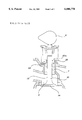
- FIG. 1 is a cross-section view illustrating a valve stem sealing device in accordance with the preferred embodiment of the present invention.
- FIG. 2 is a cross-section view illustrating a valve stem sealing device in accordance with the prior art.
- FIG. 1 shows the construction of a valve stem sealing device according to the preferred embodiment of this invention.
- the valve stem sealing device comprises a support member 66, oil seal 60 and needle bearing 64.
- the support member 66 includes an upper annular flange 66b inwardly extending from the end of a cylindrical side wall 66a, and a lower annular flange 66c inwardly extending from the central portion of the cylindrical side wall 66a.
- the support member 66 has a recess opened toward a valve stem 52, with the recess being formed between the upper annular flange 66b and the lower annular flange 66c.
- the oil seal 60 is rotatably inserted into the recess of the support member 66.
- the needle bearing 64 is positioned between the oil seal 60 and the cylindrical side wall 66a.
- the oil seal 60 has an annular sharp blade 60a, which inwardly extends from the inner surface of the oil seal 60 and comes into contact with the valve stem 52.
- a support cap 62 covers the outside wall of the oil seal 60, with the top and bottom ends of the support cap 62 being inwardly bent, thus forming top and bottom annular flanges.
- the outside wall of the support cap 62 is brought into contact with the needle bearing 64.
- the top end of a valve guide 57 is fitted into the opening formed by both the side wall 66a and the lower annular flange 66c of the support member 66, with a rubber member 68 being tightly interposed between the support member 66 and the valve guide 57.
- the vibrations caused by the valve operation are absorbed by the rubber member 68.
- the inner diameter of the oil seal 60 is smaller than that of either the flanges of the support member 66 or the support cap 62, thus allowing the seal 60 to come into close contact with the valve stem 52.
- both the support member 66 and the support cap 62 are made of a certain thickness steel plate with a high durability and heat-resistance.
- a port 45 which may be an intake or an exhaust port, is opened or closed by the reciprocating motion of the valve according to the rotation of a cam 40, thereby allowing the piston in the cylinder to perform the continued stroke and generate the engine output power.
- the valve stem 52 is repeatedly and vertically moved under the guide of the valve guide 57, with the oil seal 60 being brought into close contact with the side wall of the valve stem 52.
- the device prevents oil from entering the combustion chamber through a gap formed between the valve guide 57 and the valve stem 52.
- the oil seal 60 is somewhat rotated along the valve stem 52 as it reciprocates. That is, because the needle bearing 64 is interposed between the support cap 62 and the support member 66, the oil seal 60 with the support cap 62 is rotated along the valve stem 52 irrespective of the support member 66 being fixed to the top of the valve guide 57.
- the valve stem sealing device in accordance with the present invention has the oil seal 60, which is rotatable along with the valve stem 52 due to the needle bearing 64 during the reciprocating motion of the valve 50. Therefore, the abrasion of the oil seal is minimized, thus remarkably improving the oil sealing effect.
Landscapes
- Engineering & Computer Science (AREA)
- Mechanical Engineering (AREA)
- General Engineering & Computer Science (AREA)
- Sealing With Elastic Sealing Lips (AREA)
- Valve-Gear Or Valve Arrangements (AREA)
Abstract
A valve stem sealing device used for preventing oil from entering a combustion chamber through a gap formed between a valve guide and a valve stem is disclosed. The valve stem sealing device comprises an annular oil seal surrounding a valve stem and an annular support member fixed to the top of the valve guide so as to hold the oil seal in its place, wherein the support member has an inwardly opening annular recess and rotatably receives the oil seal in the recess, with a bearing being positioned between said oil seal and the side wall of the support member. In addition, a rubber member is tightly interposed between the support member and the valve guide so as to absorb the vibrations caused by a valve operation. Also, a support cap covers the outside wall of the oil seal so that the outside wall of the support cap is brought into contact with the bearing.
Description
1. Field of the Invention
The present invention relates, in general, to a valve stem sealing device used for preventing oil from entering a combustion chamber through a gap formed between a valve guide and a valve stem and, more particularly, to a valve stem sealing device with an oil seal being capable of rotation with the valve stem, thereby preventing the oil seal from being abraded and the oil from entering the combustion chamber.
2. Description of the Prior Art
As well known to those skilled in the art, an intake valve is mounted to an internal combustion engine, thus allowing a mixed fuel to flow into a combustion chamber. Also, the engine has an exhaust valve for exhausting combustion gas into the atmosphere.
FIG. 2 shows the construction of one typical valve, which may be an intake or an exhaust valve for internal combustion engines. It is important to note that the two valves are the same construction.
As shown in FIG. 2, a port 3 of a combustion chamber is opened or closed by the reciprocating motion of the valve which is driven by the rotating motion of a cam 2. The valve stem 12 of the valve 10 vertically reciprocates under the guide of a valve guide 7 of a cylinder head.
The cylinder head, with the cam 2, also has a valve control mechanism. In order to effectively operate both the cam 2 and the valve control mechanism, cooling and lubrication oil is supplied into the cylinder head.
However, the lubrication oil may be unexpectedly introduced into the combustion chamber through a gap formed between the valve guide 7 and the valve stem 12, thus reducing the combustion efficiency of the engine. Furthermore, such an unexpected introduction of oil into the combustion chamber may cause the engine to break down. Thus, it is preferable to mount an oil seal 20 onto the top of the valve guide 7 in an effort to prevent such an introduction of oil into the combustion chamber.
The oil seal 20 is fitted over the valve stem 12, with a support means 22 surrounding the seal 20 so as to hold the seal 20 in its place. The support means 22 is preferably made of a steel plate having a certain thickness. The support means 22 is fixed onto the top of the valve guide 7. The oil seal 20 has an annular blade 20a, which inwardly extends from the inner surface of the seal 20 and comes into close and movable contact with the side wall of the valve stem 12.
Thus, the oil seal 20 removes any gap from the junction between the valve guide 7 and the valve stem 12. That is, the valve stem 12 vertically reciprocates the inside of the oil seal 20, with the annular blade 20a being brought into close contact with the side wall of the valve stem 12, thereby preventing the oil from entering the combustion chamber.
When the valve 10 is reciprocally moved, the valve 10 is somewhat rotated. Also, in the operation of the valve, the valve head 14 comes into repeated contact with the port 3 at a high speed. As a result, the combustion chamber is repeatedly opened or closed by the reciprocating and rotating motion of the valve head 14.
However, in such a valve stem sealing device structure according to the prior art, the annular blade 20a of the oil seal 20 is quickly abraded due to the rotating motion of the valve 10, with the oil seal 20 being fixed to the top the valve guide 7 by the support means 22. Therefore, the typical sealing device may fail to prevent oil from flowing into the combustion chamber. In such a case, the sealing device reduces the combustion efficiency of an engine and, cause the engine to break down.
Accordingly, the present invention has been made in view of the above problems occurring in the prior art, and an object of the present invention is to provide a valve stem sealing device for engines, capable of rotating along with a valve stem, thereby not only preventing oil from unexpectedly entering a combustion chamber but also preventing the oil seal from being abraded, resulting in a reduction of oil consumption and an improvement in the combustion efficiency of an engine.
In order to accomplish the above object, the present invention provides a valve stem sealing device, comprising an annular oil seal surrounding a valve stem for preventing oil from entering a combustion chamber and an annular support member fixed to the top of a valve guide so as to hold said oil seal in its place, wherein said support member has an inwardly opening annular recess and rotatably receives said oil seal in said recess, with a bearing being positioned between said oil seal and the side wall of said support member.
The above object, and other features and advantages of the present invention will be more clearly understood from the following detailed description taken in conjunction with the accompanying drawings, in which:
FIG. 1 is a cross-section view illustrating a valve stem sealing device in accordance with the preferred embodiment of the present invention; and
FIG. 2 is a cross-section view illustrating a valve stem sealing device in accordance with the prior art.
FIG. 1 shows the construction of a valve stem sealing device according to the preferred embodiment of this invention.
As shown in FIG. 1, the valve stem sealing device comprises a support member 66, oil seal 60 and needle bearing 64. The support member 66 includes an upper annular flange 66b inwardly extending from the end of a cylindrical side wall 66a, and a lower annular flange 66c inwardly extending from the central portion of the cylindrical side wall 66a. Also, the support member 66 has a recess opened toward a valve stem 52, with the recess being formed between the upper annular flange 66b and the lower annular flange 66c.
The oil seal 60 is rotatably inserted into the recess of the support member 66. The needle bearing 64 is positioned between the oil seal 60 and the cylindrical side wall 66a.
The oil seal 60 has an annular sharp blade 60a, which inwardly extends from the inner surface of the oil seal 60 and comes into contact with the valve stem 52. A support cap 62 covers the outside wall of the oil seal 60, with the top and bottom ends of the support cap 62 being inwardly bent, thus forming top and bottom annular flanges. The outside wall of the support cap 62 is brought into contact with the needle bearing 64. The top end of a valve guide 57 is fitted into the opening formed by both the side wall 66a and the lower annular flange 66c of the support member 66, with a rubber member 68 being tightly interposed between the support member 66 and the valve guide 57. Thus, the vibrations caused by the valve operation are absorbed by the rubber member 68.
The inner diameter of the oil seal 60 is smaller than that of either the flanges of the support member 66 or the support cap 62, thus allowing the seal 60 to come into close contact with the valve stem 52. Preferably, both the support member 66 and the support cap 62 are made of a certain thickness steel plate with a high durability and heat-resistance.
The operational effect of the device of this invention is described below.
A port 45, which may be an intake or an exhaust port, is opened or closed by the reciprocating motion of the valve according to the rotation of a cam 40, thereby allowing the piston in the cylinder to perform the continued stroke and generate the engine output power. In such an operation, the valve stem 52 is repeatedly and vertically moved under the guide of the valve guide 57, with the oil seal 60 being brought into close contact with the side wall of the valve stem 52. Thus, the device prevents oil from entering the combustion chamber through a gap formed between the valve guide 57 and the valve stem 52.
In the operation of the valve, the oil seal 60 is somewhat rotated along the valve stem 52 as it reciprocates. That is, because the needle bearing 64 is interposed between the support cap 62 and the support member 66, the oil seal 60 with the support cap 62 is rotated along the valve stem 52 irrespective of the support member 66 being fixed to the top of the valve guide 57.
During the reciprocating motion of the valve 50, the vibrations, which are transmitted to the valve guide 57 or the oil seal 60, are effectively absorbed by the rubber member 68 positioned between the support member 66 and the valve guide 57.
As mentioned above, the valve stem sealing device in accordance with the present invention has the oil seal 60, which is rotatable along with the valve stem 52 due to the needle bearing 64 during the reciprocating motion of the valve 50. Therefore, the abrasion of the oil seal is minimized, thus remarkably improving the oil sealing effect.
Although the preferred embodiments of the invention have been disclosed for illustrative purposes, those skilled in the art will appreciate that various modifications, additions and substitutions are possible, without departing from the scope and spirit of the invention as disclosed in the accompanying claims.
Claims (8)
1. A valve stem sealing device for preventing oil from entering a combustion chamber, the valve stem sealing device comprising:
an annular oil seal surrounding the valve stem;
an upper annular flange;
a lower annular flange, wherein the upper annular flange and the lower annular flange hold said oil seal in place;
a valve guide which guides the valve stem;
an annular support member fixed to a top of the valve guide so as to hold the oil seal in position, wherein the annular support member has an inwardly opening annular recess that rotatably receives the oil seal; and
a bearing which allows the oil seal to rotate with respect to the annular support member, wherein the bearing is positioned between the annular oil seal and the cylindrical side wall of said support member so as to quicken the rotation of said oil seal along said valve stem during reciprocating motion of said valve stem so as to minimize abrasion of said oil seal as said seal wipes said valve stem.
2. The valve stem sealing device as claimed in claim 1, wherein a rubber member is tightly interposed between said support member and said valve guide so as to absorb the vibrations caused by a valve operation.
3. The valve stem sealing device as claimed in claim 1, wherein a support cap covers the outside wall of said oil seal so that the outside wall of said support cap is brought into contact with said bearing.
4. The valve stem sealing device as claimed in claim 3, wherein the support cap has top and bottom ends inwardly bent so as to form top and bottom annular flanges.
5. The valve stem sealing device as claimed in claim 4, wherein the oil seal has an inner diameter smaller either the flanges of the support cap or the recess formed by the support member, thereby allowing the seal to come into close contact with the valve stem.
6. The valve stem sealing device as claimed in claim 3, wherein both the support member and the support cap are comprised of steel plate.
7. The valve stem sealing device as claimed in claim 1, wherein the oil seal has an annular sharp blade which inwardly extends from an inner surface of the oil seal and comes into contact with the valve stem.
8. The valve stem sealing device as claimed in claim 1, wherein the bearing is a needle bearing.
Applications Claiming Priority (2)
| Application Number | Priority Date | Filing Date | Title |
|---|---|---|---|
| KR96-33401 | 1996-10-10 | ||
| KR2019960033401U KR0130985Y1 (en) | 1996-10-10 | 1996-10-10 | Valve stem seal mounting device |
Publications (1)
| Publication Number | Publication Date |
|---|---|
| US6006778A true US6006778A (en) | 1999-12-28 |
Family
ID=19469351
Family Applications (1)
| Application Number | Title | Priority Date | Filing Date |
|---|---|---|---|
| US08/947,878 Expired - Fee Related US6006778A (en) | 1996-10-10 | 1997-10-09 | Device for sensing the amount of oil in oil pans |
Country Status (3)
| Country | Link |
|---|---|
| US (1) | US6006778A (en) |
| JP (1) | JP3062736B2 (en) |
| KR (1) | KR0130985Y1 (en) |
Cited By (11)
| Publication number | Priority date | Publication date | Assignee | Title |
|---|---|---|---|---|
| US6318328B1 (en) * | 2000-10-10 | 2001-11-20 | Dana Corporation | Dry valve stem seal |
| US6354566B1 (en) * | 2000-07-24 | 2002-03-12 | General Valve, Inc. | Live loaded valve stem packing with shape memory alloy option |
| EP1247947A3 (en) * | 2001-04-07 | 2003-08-06 | Volkswagen Aktiengesellschaft | Direct injection engine |
| US20040010809A1 (en) * | 2002-07-12 | 2004-01-15 | Wolf C. Roland | Modulation of cytochrome P450 reductase activity |
| US6764063B2 (en) | 2001-02-06 | 2004-07-20 | Dana Corporation | Valve seal assembly with bottom flange seal |
| US7025030B2 (en) | 2003-08-21 | 2006-04-11 | Dana Corporation | Valve stem seal assembly with changeable cap |
| US20060169942A1 (en) * | 2005-02-03 | 2006-08-03 | Hesher Eric W | Oil metering valve seal |
| CN100347434C (en) * | 2003-10-17 | 2007-11-07 | 三菱电机株式会社 | Valve, exhaust gas recirculation control valve and valve assembling method |
| CN104251305A (en) * | 2013-06-26 | 2014-12-31 | 福特全球技术公司 | Control of fluid flow in an automatic transmission |
| US20180135476A1 (en) * | 2016-11-14 | 2018-05-17 | Man Diesel & Turbo Se | Gas Exchange Valve For An Internal Combustion Engine And Internal Combustion Engine |
| US11239128B2 (en) | 2005-08-19 | 2022-02-01 | Micron Technology, Inc. | Microelectronic devices, stacked microelectronic devices, and methods for manufacturing microelectronic devices |
Citations (13)
| Publication number | Priority date | Publication date | Assignee | Title |
|---|---|---|---|---|
| US1954643A (en) * | 1931-01-13 | 1934-04-10 | Hughes Tool Co | Valve stem packing |
| US3409337A (en) * | 1966-07-05 | 1968-11-05 | Torrington Co | Sealed roller bearing |
| US3442517A (en) * | 1966-11-02 | 1969-05-06 | Renniks Corp | Seal |
| US3447848A (en) * | 1965-06-24 | 1969-06-03 | Nadella | Journal rolling bearing having a built-in sealing element |
| US4356997A (en) * | 1980-09-29 | 1982-11-02 | Quality Valve And Machine Works, Inc. | Flow control mechanism for high pressure wells |
| US4611931A (en) * | 1984-03-31 | 1986-09-16 | Skf Gmbh | Sealed roller bearing |
| US4706967A (en) * | 1987-03-27 | 1987-11-17 | General Motors Corporation | Valve guide seal device |
| US4763618A (en) * | 1987-04-03 | 1988-08-16 | Microdot Inc. | Valve stem oil deflector |
| US4811704A (en) * | 1988-03-07 | 1989-03-14 | Vernay Laboratories, Inc. | Valve stem seal |
| US4811960A (en) * | 1987-08-10 | 1989-03-14 | Microdot Inc. | Fixed valve stem oil seal |
| US4834037A (en) * | 1987-10-14 | 1989-05-30 | Dana Corporation | Unitary molded plastic valve seal |
| US5370404A (en) * | 1992-03-27 | 1994-12-06 | Firma Carl Freudenberg | Radial lip seal with interposed bearing |
| US5387040A (en) * | 1993-04-30 | 1995-02-07 | Reliance Electric Industrial Company | Sealing system |
-
1996
- 1996-10-10 KR KR2019960033401U patent/KR0130985Y1/en not_active Expired - Fee Related
-
1997
- 1997-10-09 US US08/947,878 patent/US6006778A/en not_active Expired - Fee Related
- 1997-10-13 JP JP9294908A patent/JP3062736B2/en not_active Expired - Lifetime
Patent Citations (13)
| Publication number | Priority date | Publication date | Assignee | Title |
|---|---|---|---|---|
| US1954643A (en) * | 1931-01-13 | 1934-04-10 | Hughes Tool Co | Valve stem packing |
| US3447848A (en) * | 1965-06-24 | 1969-06-03 | Nadella | Journal rolling bearing having a built-in sealing element |
| US3409337A (en) * | 1966-07-05 | 1968-11-05 | Torrington Co | Sealed roller bearing |
| US3442517A (en) * | 1966-11-02 | 1969-05-06 | Renniks Corp | Seal |
| US4356997A (en) * | 1980-09-29 | 1982-11-02 | Quality Valve And Machine Works, Inc. | Flow control mechanism for high pressure wells |
| US4611931A (en) * | 1984-03-31 | 1986-09-16 | Skf Gmbh | Sealed roller bearing |
| US4706967A (en) * | 1987-03-27 | 1987-11-17 | General Motors Corporation | Valve guide seal device |
| US4763618A (en) * | 1987-04-03 | 1988-08-16 | Microdot Inc. | Valve stem oil deflector |
| US4811960A (en) * | 1987-08-10 | 1989-03-14 | Microdot Inc. | Fixed valve stem oil seal |
| US4834037A (en) * | 1987-10-14 | 1989-05-30 | Dana Corporation | Unitary molded plastic valve seal |
| US4811704A (en) * | 1988-03-07 | 1989-03-14 | Vernay Laboratories, Inc. | Valve stem seal |
| US5370404A (en) * | 1992-03-27 | 1994-12-06 | Firma Carl Freudenberg | Radial lip seal with interposed bearing |
| US5387040A (en) * | 1993-04-30 | 1995-02-07 | Reliance Electric Industrial Company | Sealing system |
Cited By (16)
| Publication number | Priority date | Publication date | Assignee | Title |
|---|---|---|---|---|
| US6354566B1 (en) * | 2000-07-24 | 2002-03-12 | General Valve, Inc. | Live loaded valve stem packing with shape memory alloy option |
| US6318328B1 (en) * | 2000-10-10 | 2001-11-20 | Dana Corporation | Dry valve stem seal |
| US6764063B2 (en) | 2001-02-06 | 2004-07-20 | Dana Corporation | Valve seal assembly with bottom flange seal |
| EP1247947A3 (en) * | 2001-04-07 | 2003-08-06 | Volkswagen Aktiengesellschaft | Direct injection engine |
| US20040010809A1 (en) * | 2002-07-12 | 2004-01-15 | Wolf C. Roland | Modulation of cytochrome P450 reductase activity |
| US7025030B2 (en) | 2003-08-21 | 2006-04-11 | Dana Corporation | Valve stem seal assembly with changeable cap |
| CN100347434C (en) * | 2003-10-17 | 2007-11-07 | 三菱电机株式会社 | Valve, exhaust gas recirculation control valve and valve assembling method |
| US7438036B2 (en) * | 2005-02-03 | 2008-10-21 | Dana Automotive Systems Group, Llc | Oil metering valve seal |
| US20060169942A1 (en) * | 2005-02-03 | 2006-08-03 | Hesher Eric W | Oil metering valve seal |
| US11239128B2 (en) | 2005-08-19 | 2022-02-01 | Micron Technology, Inc. | Microelectronic devices, stacked microelectronic devices, and methods for manufacturing microelectronic devices |
| CN104251305A (en) * | 2013-06-26 | 2014-12-31 | 福特全球技术公司 | Control of fluid flow in an automatic transmission |
| US20150001026A1 (en) * | 2013-06-26 | 2015-01-01 | Ford Global Technologies, Llc | Control of fluid flow in an automatic transmission |
| US9004253B2 (en) * | 2013-06-26 | 2015-04-14 | Ford Global Technologies, Llc | Control of fluid flow in an automatic transmission |
| CN104251305B (en) * | 2013-06-26 | 2018-07-06 | 福特全球技术公司 | Fluid flow control assembly in automatic transmission |
| US20180135476A1 (en) * | 2016-11-14 | 2018-05-17 | Man Diesel & Turbo Se | Gas Exchange Valve For An Internal Combustion Engine And Internal Combustion Engine |
| CN108071438A (en) * | 2016-11-14 | 2018-05-25 | 曼柴油机和涡轮机欧洲股份公司 | For the scavenging air valve and internal combustion engine of internal combustion engine |
Also Published As
| Publication number | Publication date |
|---|---|
| JPH10176512A (en) | 1998-06-30 |
| KR19980020190U (en) | 1998-07-15 |
| KR0130985Y1 (en) | 1999-10-01 |
| JP3062736B2 (en) | 2000-07-12 |
Similar Documents
| Publication | Publication Date | Title |
|---|---|---|
| US6006778A (en) | Device for sensing the amount of oil in oil pans | |
| US4977869A (en) | Valve assembly for internal-combustion engines | |
| CN1390277A (en) | Cylinder head with compound motion oval valves | |
| KR100216442B1 (en) | Cooling system of automobile engine valve | |
| KR200161848Y1 (en) | Valve device for reducing oil consumption | |
| KR200245692Y1 (en) | Valve stem oil seal with integral valve spring seat | |
| JPH07174025A (en) | Four-cycle internal combustion engine | |
| KR200184896Y1 (en) | Internal combustion engine valve rotary device | |
| KR0128312Y1 (en) | Spring structure for intake / exhaust valve of internal combustion engine | |
| US20040060532A1 (en) | Piston valve internal combustion engine | |
| KR19990003235U (en) | Engine intake / exhaust device with helical valve step guide | |
| KR20020019147A (en) | Gasket for sealing of cylinder head cover | |
| KR100248330B1 (en) | Engine having a suction and exhaust valve | |
| KR100224347B1 (en) | Valve stem seal | |
| KR100245877B1 (en) | Valve mechanism of engine | |
| JPS62267522A (en) | 2-cycle engine exhaust timing control device | |
| KR100212881B1 (en) | Combination structure of valve guide and valve stem seal | |
| JPH0472065B2 (en) | ||
| JPS6187951A (en) | Overhead-valve type air-cooled internal-combustion engine | |
| KR19980045826A (en) | Overhead Camshaft Rocker Arms | |
| KR19980045603U (en) | Lubrication structure of valve mechanism for internal combustion engine | |
| KR19980055479A (en) | Valve opening and closing device of automobile | |
| KR19990058228A (en) | Vane mounted valve | |
| KR19980051774U (en) | Engine Valve Cooling System | |
| KR19980037398U (en) | Valve seal member |
Legal Events
| Date | Code | Title | Description |
|---|---|---|---|
| AS | Assignment |
Owner name: HYUNDAI MOTOR COMPANY, KOREA, REPUBLIC OF Free format text: ASSIGNMENT OF ASSIGNORS INTEREST;ASSIGNOR:KIM, GYU WAN;REEL/FRAME:008839/0444 Effective date: 19971107 |
|
| CC | Certificate of correction | ||
| REMI | Maintenance fee reminder mailed | ||
| LAPS | Lapse for failure to pay maintenance fees | ||
| STCH | Information on status: patent discontinuation |
Free format text: PATENT EXPIRED DUE TO NONPAYMENT OF MAINTENANCE FEES UNDER 37 CFR 1.362 |
|
| FP | Lapsed due to failure to pay maintenance fee |
Effective date: 20031228 |