US6006573A - Driven ductility machine - Google Patents
Driven ductility machine Download PDFInfo
- Publication number
- US6006573A US6006573A US08/853,571 US85357197A US6006573A US 6006573 A US6006573 A US 6006573A US 85357197 A US85357197 A US 85357197A US 6006573 A US6006573 A US 6006573A
- Authority
- US
- United States
- Prior art keywords
- metal wire
- rollers
- roller
- cold flow
- flow unit
- Prior art date
- Legal status (The legal status is an assumption and is not a legal conclusion. Google has not performed a legal analysis and makes no representation as to the accuracy of the status listed.)
- Expired - Fee Related
Links
Images


Classifications
-
- B—PERFORMING OPERATIONS; TRANSPORTING
- B21—MECHANICAL METAL-WORKING WITHOUT ESSENTIALLY REMOVING MATERIAL; PUNCHING METAL
- B21F—WORKING OR PROCESSING OF METAL WIRE
- B21F9/00—Straining wire
- B21F9/005—Straining wire to affect the material properties of the wire
-
- B—PERFORMING OPERATIONS; TRANSPORTING
- B21—MECHANICAL METAL-WORKING WITHOUT ESSENTIALLY REMOVING MATERIAL; PUNCHING METAL
- B21F—WORKING OR PROCESSING OF METAL WIRE
- B21F9/00—Straining wire
Definitions
- the present invention relates to a cold flow unit for metal wire for the purpose of improving the tensile strength and increasing the ductility of the metal wire and, in other words, to provide the wire with optimum properties for further use.
- the present invention is based on the insight that by causing a metal wire to transfer practically immediately successively from a positive radius to a negative radius and vice versa, cold flow occurs whereby the above mentioned properties improve. By causing this transition in radius to take place a number of times not only is an improvement of the properties obtained but such a cold flow unit can likewise be used to transport the metal wire during processing.
- the transition in the radius must preferably take place directly in view of the length of the metal wire.
- cold flow occurs if the transition distance between the points of contact, i.e. likewise the transition in the radius, is less than 5 times the metal wire diameter.
- Better cold flow is obtained if this transition distance is less than 4 times, preferably less than 3 times the metal wire diameter. Very good cold flow is obtained at a transition distance less than 2.5 times the metal wire diameter.
- the improvement in properties can increase further by using more than 3 rollers, for instance at least 4 and more preferably at least 5.
- the cold flow unit is used in a device in which the wire is further processed in units which employ a discontinuous wire processing, such as during aligning of the wire and performing of welding operations thereon, it is recommended to continuously adapt the delivery speed of the cold flow unit with a view to these further devices.
- the cold flow unit is preferably provided with a rotation speed control for each roller in order to control a roller rotation speed subject to the desired delivery speed of the processed metal wire.
- a sensor preferably for use therein measures the sagging of the metal wire between the cold flow unit and the subsequent processing unit and this sensor then actuates the rotation speed control.
- Another aspect of the present invention relates to a device for processing metal wire, which device contains in addition to the above mentioned cold flow unit according to the invention a roller cassette. It is otherwise also possible to first perform a thinning operation on the metal wire and optionally a profile-arranging operation and subsequently to cause the cold flow to take place in the cold flow unit according to the invention. Transporting means for transport from the metal wire delivery into the cold flow unit can then for instance be dispensed with and metal wire stretching can take place between the devices.
- two successive cold flow units are used.
- the transport between the two units takes place with or without stretching. It is thus possible to obtain metal wire with optimum properties.
- FIG. 1 shows a schematic view of a device for processing metal wire
- FIG. 2 shows schematically on larger scale a cold flow unit according to the invention used in the device of FIG. 1;
- FIG. 3 shows on larger scale a variant of the device of FIG. 2 and
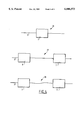
- FIG. 4 shows a number of flow diagrams for devices for processing metal wire according to the invention.
- FIG. 1 shows a device 1 according to the invention.
- the processing device 1 comprises a reel 2 for supplying metal wire from a supply location 4.
- the metal wire 3 is fed via a guide unit 5 to a roller cassette 6 in which an aligning and profiling operation is performed on metal wire 3.
- a roller cassette 6 is described in the European patent application 601,630 which is herein incorporated by reference.
- the metal wire 3 reaches the cold flow unit 7 according to the invention.
- the delivery speed of cold flow unit 7 is controlled using a rotation speed control 8 which is actuated with a sensor 9.
- the metal wire 3 eventually reaches a unit 10 for straightening the wire, cutting the wire and/or optionally welding the wire.
- FIG. 2 shows in more detail the structure of cold flow unit 7.
- Cold flow unit 7 comprises 5 rollers 11-15, over a part of the roller periphery of which the metal wire 3 is trained.
- the rollers 11-15 are herein mutually oriented such that in this case the transition distance between the points of contact during the transfer of metal wire 3 from the one roller 11 to the following roller 12 does not exceed a determined magnitude.
- the transition distances at the position of the contact points 17-20 are zero.
- the metal wire is thus subjected to an almost direct transition from a positive to a negative radius or vice versa.
- the points of contact 16 and 21 indicate the locations where the metal wire is trained onto roller 11 and respectively leaves roller 15.
- rollers 11-15 are placed in a frame such that a friction contact is possible between metal wire and roller and that during passage of the wire through cold flow unit 7 the tension in the metal wire decreases but the stretch improves optimally.
- FIG. 3 shows a variant.
- the metal wire 3 which in roller cassette 6 is provided inter alia with indentations 22, is trained round the rollers 11 and 12 wherein in this case there is a transition distance between the points of contact 23 and 24.
- the metal wire leaves roller 11 and at contact point 24 it is trained round roller 12.
- This transition distance 25 between rollers 11 and 12 is in this case roughly equal to 2.5 times the metal wire diameter.
- FIG. 4 shows a number of devices for processing the metal wire 3.
- the metal wire 3 is processed solely in cold flow unit 7 whereby a wire is obtained with an optimum stretching ductility.
- a roller cassette 6 and a cold flow unit 7 are connected successively as shown in FIG. 1. In this case separate transporting means can thus be omitted, while the wire can be stretched between the two units 6 and 7.
Abstract
Description
Claims (11)
Applications Claiming Priority (2)
| Application Number | Priority Date | Filing Date | Title |
|---|---|---|---|
| NL1003078A NL1003078C2 (en) | 1996-05-10 | 1996-05-10 | Powered ductility machine. |
| NL1003078 | 1996-05-10 |
Publications (1)
| Publication Number | Publication Date |
|---|---|
| US6006573A true US6006573A (en) | 1999-12-28 |
Family
ID=19762831
Family Applications (1)
| Application Number | Title | Priority Date | Filing Date |
|---|---|---|---|
| US08/853,571 Expired - Fee Related US6006573A (en) | 1996-05-10 | 1997-05-09 | Driven ductility machine |
Country Status (7)
| Country | Link |
|---|---|
| US (1) | US6006573A (en) |
| EP (1) | EP0806257B1 (en) |
| AT (1) | ATE236748T1 (en) |
| DE (1) | DE69720582T2 (en) |
| DK (1) | DK0806257T3 (en) |
| ES (1) | ES2197296T3 (en) |
| NL (1) | NL1003078C2 (en) |
Cited By (2)
| Publication number | Priority date | Publication date | Assignee | Title |
|---|---|---|---|---|
| US20120186689A1 (en) * | 2011-01-21 | 2012-07-26 | Burns Thomas W | Assembly for assisting the removal from storage and transfer of wire |
| CN107876580A (en) * | 2017-09-30 | 2018-04-06 | 李文华 | A kind of multifunctional steel wire coil winder to be derusted with straightening |
Families Citing this family (2)
| Publication number | Priority date | Publication date | Assignee | Title |
|---|---|---|---|---|
| AT407719B (en) * | 1998-02-10 | 2001-05-25 | Evg Entwicklung Verwert Ges | METHOD AND SYSTEM FOR PRODUCING GRID MATS |
| NL2009282C2 (en) * | 2012-08-03 | 2014-02-06 | Znd Draad B V | Method, apparatus and arrangement for manufacturing reinforcement steel, and reinforcement steel manufactured therewith. |
Citations (15)
| Publication number | Priority date | Publication date | Assignee | Title |
|---|---|---|---|---|
| US1824568A (en) * | 1929-10-25 | 1931-09-22 | Nat Standard Co | Method of treating wire |
| US2332796A (en) * | 1941-01-25 | 1943-10-26 | Carnegie Illinois Steel Corp | Reduction of elongated bodies |
| US3247946A (en) * | 1962-10-30 | 1966-04-26 | American Can Co | Method of treating metal |
| US3253445A (en) * | 1962-07-09 | 1966-05-31 | Metal Box Co Ltd | Apparatus for rolling strip metal |
| US3326025A (en) * | 1964-08-14 | 1967-06-20 | Nishioka Tasaburo | Apparatus for alternately bending to draw wire or plate |
| US3389591A (en) * | 1965-12-27 | 1968-06-25 | Canada Steel Co | Bridle |
| US3394574A (en) * | 1965-04-02 | 1968-07-30 | Metal Box Co Ltd | Treatment of strip metal |
| GB1150166A (en) * | 1965-06-18 | 1969-04-30 | United States Steel Corp | Method and Apparatus for Cold-Reducing Strip. |
| US3605470A (en) * | 1969-01-27 | 1971-09-20 | Natalis H Polakowski | Pressure assisted tension roller leveler |
| US3777532A (en) * | 1971-07-09 | 1973-12-11 | Berg Und Walzwerk Maschinen Gm | Method of and apparatus for extending and reducing thickness of a metallic band |
| US3798950A (en) * | 1971-03-05 | 1974-03-26 | Metal Box Co Ltd | Treating strip metal |
| US3964848A (en) * | 1973-09-15 | 1976-06-22 | Hermann Berstorff Maschinenbau Gmbh | Calendering of synthetic plastics film |
| GB2214846A (en) * | 1988-02-20 | 1989-09-13 | Allied Steel Wire Ltd | Method and apparatus for treating wire |
| JPH0386320A (en) * | 1989-08-31 | 1991-04-11 | Kawasaki Steel Corp | Driving device for roller leveler |
| US5611190A (en) * | 1992-12-09 | 1997-03-18 | Van Merksteijn; Jacobus L. | Metal rod and a method for manufacturing same |
-
1996
- 1996-05-10 NL NL1003078A patent/NL1003078C2/en not_active IP Right Cessation
-
1997
- 1997-05-09 US US08/853,571 patent/US6006573A/en not_active Expired - Fee Related
- 1997-05-09 AT AT97201408T patent/ATE236748T1/en not_active IP Right Cessation
- 1997-05-09 DK DK97201408T patent/DK0806257T3/en active
- 1997-05-09 ES ES97201408T patent/ES2197296T3/en not_active Expired - Lifetime
- 1997-05-09 EP EP97201408A patent/EP0806257B1/en not_active Expired - Lifetime
- 1997-05-09 DE DE69720582T patent/DE69720582T2/en not_active Expired - Fee Related
Patent Citations (15)
| Publication number | Priority date | Publication date | Assignee | Title |
|---|---|---|---|---|
| US1824568A (en) * | 1929-10-25 | 1931-09-22 | Nat Standard Co | Method of treating wire |
| US2332796A (en) * | 1941-01-25 | 1943-10-26 | Carnegie Illinois Steel Corp | Reduction of elongated bodies |
| US3253445A (en) * | 1962-07-09 | 1966-05-31 | Metal Box Co Ltd | Apparatus for rolling strip metal |
| US3247946A (en) * | 1962-10-30 | 1966-04-26 | American Can Co | Method of treating metal |
| US3326025A (en) * | 1964-08-14 | 1967-06-20 | Nishioka Tasaburo | Apparatus for alternately bending to draw wire or plate |
| US3394574A (en) * | 1965-04-02 | 1968-07-30 | Metal Box Co Ltd | Treatment of strip metal |
| GB1150166A (en) * | 1965-06-18 | 1969-04-30 | United States Steel Corp | Method and Apparatus for Cold-Reducing Strip. |
| US3389591A (en) * | 1965-12-27 | 1968-06-25 | Canada Steel Co | Bridle |
| US3605470A (en) * | 1969-01-27 | 1971-09-20 | Natalis H Polakowski | Pressure assisted tension roller leveler |
| US3798950A (en) * | 1971-03-05 | 1974-03-26 | Metal Box Co Ltd | Treating strip metal |
| US3777532A (en) * | 1971-07-09 | 1973-12-11 | Berg Und Walzwerk Maschinen Gm | Method of and apparatus for extending and reducing thickness of a metallic band |
| US3964848A (en) * | 1973-09-15 | 1976-06-22 | Hermann Berstorff Maschinenbau Gmbh | Calendering of synthetic plastics film |
| GB2214846A (en) * | 1988-02-20 | 1989-09-13 | Allied Steel Wire Ltd | Method and apparatus for treating wire |
| JPH0386320A (en) * | 1989-08-31 | 1991-04-11 | Kawasaki Steel Corp | Driving device for roller leveler |
| US5611190A (en) * | 1992-12-09 | 1997-03-18 | Van Merksteijn; Jacobus L. | Metal rod and a method for manufacturing same |
Cited By (6)
| Publication number | Priority date | Publication date | Assignee | Title |
|---|---|---|---|---|
| US20120186689A1 (en) * | 2011-01-21 | 2012-07-26 | Burns Thomas W | Assembly for assisting the removal from storage and transfer of wire |
| US8635896B2 (en) * | 2011-01-21 | 2014-01-28 | Alcotec Wire Corporation | Assembly for assisting the removal from storage and transfer of wire |
| US20140091070A1 (en) * | 2011-01-21 | 2014-04-03 | Alcotec Wire Corporation | Assembly for assisting the removal from storage and transfer of wire |
| US8813531B2 (en) * | 2011-01-21 | 2014-08-26 | Alcotec Wire Corporation | Assembly for assisting the removal from storage and transfer of wire |
| AU2012207539B2 (en) * | 2011-01-21 | 2015-01-22 | Alcotec Wire Corporation | Assembly for assisting the removal from storage and transfer of wire |
| CN107876580A (en) * | 2017-09-30 | 2018-04-06 | 李文华 | A kind of multifunctional steel wire coil winder to be derusted with straightening |
Also Published As
| Publication number | Publication date |
|---|---|
| DE69720582T2 (en) | 2004-02-12 |
| ES2197296T3 (en) | 2004-01-01 |
| ATE236748T1 (en) | 2003-04-15 |
| EP0806257B1 (en) | 2003-04-09 |
| DE69720582D1 (en) | 2003-05-15 |
| EP0806257A1 (en) | 1997-11-12 |
| NL1003078C2 (en) | 1997-11-18 |
| DK0806257T3 (en) | 2003-07-21 |
Similar Documents
| Publication | Publication Date | Title |
|---|---|---|
| JP2004092014A (en) | Apparatus for converging drafted fiber strand | |
| ES2015138A6 (en) | Method and apparatus for severing the sliver in sliver coilers | |
| US6006573A (en) | Driven ductility machine | |
| JPH10511632A (en) | Winding device | |
| JPH01314739A (en) | False twister | |
| JPS61269945A (en) | Device for preventing revolution of rod | |
| RU94002332A (en) | METHOD OF DIRECTION OF A STEEL TAPE AT ITS MOVEMENT THROUGH AN INSTALLATION FOR CONTINUOUS TREATMENT AND A DEVICE FOR ITS IMPLEMENTATION | |
| US5406818A (en) | Opening apparatus having an alignment system for producing a continuous metal strip from a split-tube | |
| CN108115002A (en) | The method for improving tail part of band steel scroll quality | |
| AU2004259883A1 (en) | Machine for yarn cabling/twisting and continuous setting | |
| US6772574B1 (en) | Binding means | |
| JPH02229225A (en) | High draft apparatus | |
| CA1036460A (en) | Method of continuously processing metal cord | |
| JP2583923Y2 (en) | Delivery device in seedling treatment machine | |
| EP1574277B1 (en) | A welding wire conveyor | |
| KR960040487A (en) | Transfer method of coil and winding device of coil | |
| JPH0521214Y2 (en) | ||
| JPH0922627A (en) | Method for controlling wire speed during extrusion covering process | |
| JP2552485Y2 (en) | Processing yarn device capable of continuous twisting of artificial yarn and further processing | |
| JP2659071B2 (en) | Induction winding method for deformed wires | |
| US20020007657A1 (en) | Multi-draw wire drawing machine | |
| JP2589670Y2 (en) | Unloading device in seedling processing machine | |
| JP2766546B2 (en) | Wire straightening device | |
| JP2584387B2 (en) | Strip winding method for continuous strip processing line | |
| CN114655773A (en) | Fiber widening and filament releasing device |
Legal Events
| Date | Code | Title | Description |
|---|---|---|---|
| AS | Assignment |
Owner name: V.M.S. HOLDING AG, SWITZERLAND Free format text: ASSIGNMENT OF ASSIGNORS INTEREST;ASSIGNOR:VAN MERKSTEIJN, JACOBUS LAMBERTUS;REEL/FRAME:008764/0092 Effective date: 19970616 |
|
| CC | Certificate of correction | ||
| REMI | Maintenance fee reminder mailed | ||
| FPAY | Fee payment |
Year of fee payment: 4 |
|
| SULP | Surcharge for late payment | ||
| FEPP | Fee payment procedure |
Free format text: PAYOR NUMBER ASSIGNED (ORIGINAL EVENT CODE: ASPN); ENTITY STATUS OF PATENT OWNER: LARGE ENTITY Free format text: PAYER NUMBER DE-ASSIGNED (ORIGINAL EVENT CODE: RMPN); ENTITY STATUS OF PATENT OWNER: LARGE ENTITY |
|
| REMI | Maintenance fee reminder mailed | ||
| FPAY | Fee payment |
Year of fee payment: 8 |
|
| SULP | Surcharge for late payment |
Year of fee payment: 7 |
|
| REMI | Maintenance fee reminder mailed | ||
| LAPS | Lapse for failure to pay maintenance fees | ||
| STCH | Information on status: patent discontinuation |
Free format text: PATENT EXPIRED DUE TO NONPAYMENT OF MAINTENANCE FEES UNDER 37 CFR 1.362 |
|
| FP | Lapsed due to failure to pay maintenance fee |
Effective date: 20111228 |