US6003176A - Universal lateral positioner - Google Patents
Universal lateral positioner Download PDFInfo
- Publication number
- US6003176A US6003176A US09/084,278 US8427898A US6003176A US 6003176 A US6003176 A US 6003176A US 8427898 A US8427898 A US 8427898A US 6003176 A US6003176 A US 6003176A
- Authority
- US
- United States
- Prior art keywords
- plate
- hyperflexion
- support
- rail
- support plate
- Prior art date
- Legal status (The legal status is an assumption and is not a legal conclusion. Google has not performed a legal analysis and makes no representation as to the accuracy of the status listed.)
- Expired - Lifetime
Links
Images


Classifications
-
- A—HUMAN NECESSITIES
- A61—MEDICAL OR VETERINARY SCIENCE; HYGIENE
- A61G—TRANSPORT, PERSONAL CONVEYANCES, OR ACCOMMODATION SPECIALLY ADAPTED FOR PATIENTS OR DISABLED PERSONS; OPERATING TABLES OR CHAIRS; CHAIRS FOR DENTISTRY; FUNERAL DEVICES
- A61G13/00—Operating tables; Auxiliary appliances therefor
- A61G13/10—Parts, details or accessories
- A61G13/12—Rests specially adapted therefor; Arrangements of patient-supporting surfaces
-
- A—HUMAN NECESSITIES
- A61—MEDICAL OR VETERINARY SCIENCE; HYGIENE
- A61G—TRANSPORT, PERSONAL CONVEYANCES, OR ACCOMMODATION SPECIALLY ADAPTED FOR PATIENTS OR DISABLED PERSONS; OPERATING TABLES OR CHAIRS; CHAIRS FOR DENTISTRY; FUNERAL DEVICES
- A61G13/00—Operating tables; Auxiliary appliances therefor
- A61G13/0036—Orthopaedic operating tables
- A61G13/0081—Orthopaedic operating tables specially adapted for hip surgeries
-
- A—HUMAN NECESSITIES
- A61—MEDICAL OR VETERINARY SCIENCE; HYGIENE
- A61G—TRANSPORT, PERSONAL CONVEYANCES, OR ACCOMMODATION SPECIALLY ADAPTED FOR PATIENTS OR DISABLED PERSONS; OPERATING TABLES OR CHAIRS; CHAIRS FOR DENTISTRY; FUNERAL DEVICES
- A61G13/00—Operating tables; Auxiliary appliances therefor
- A61G13/10—Parts, details or accessories
- A61G13/12—Rests specially adapted therefor; Arrangements of patient-supporting surfaces
- A61G13/1205—Rests specially adapted therefor; Arrangements of patient-supporting surfaces for specific parts of the body
- A61G13/1225—Back
-
- A—HUMAN NECESSITIES
- A61—MEDICAL OR VETERINARY SCIENCE; HYGIENE
- A61G—TRANSPORT, PERSONAL CONVEYANCES, OR ACCOMMODATION SPECIALLY ADAPTED FOR PATIENTS OR DISABLED PERSONS; OPERATING TABLES OR CHAIRS; CHAIRS FOR DENTISTRY; FUNERAL DEVICES
- A61G13/00—Operating tables; Auxiliary appliances therefor
- A61G13/10—Parts, details or accessories
- A61G13/12—Rests specially adapted therefor; Arrangements of patient-supporting surfaces
- A61G13/1205—Rests specially adapted therefor; Arrangements of patient-supporting surfaces for specific parts of the body
- A61G13/123—Lower body, e.g. pelvis, hip, buttocks
-
- A—HUMAN NECESSITIES
- A61—MEDICAL OR VETERINARY SCIENCE; HYGIENE
- A61G—TRANSPORT, PERSONAL CONVEYANCES, OR ACCOMMODATION SPECIALLY ADAPTED FOR PATIENTS OR DISABLED PERSONS; OPERATING TABLES OR CHAIRS; CHAIRS FOR DENTISTRY; FUNERAL DEVICES
- A61G2200/00—Information related to the kind of patient or his position
- A61G2200/30—Specific positions of the patient
- A61G2200/32—Specific positions of the patient lying
- A61G2200/322—Specific positions of the patient lying lateral
Definitions
- U.S. Pat. No. 3,844,550 entitled “Pelvic Support for Surgical Operations” describes one such support that is secured to an operating table or the like.
- the support includes a pair of anterior and posterior support braces for supporting a patient securely in the lateral decubitus position for surgeries of the hip.
- the anterior and posterior support braces are mounted on a support plate that allows the movement of the braces in the horizontal plane to compensate for the size and structure of the specific patient.
- one purpose of the invention is to describe a hyperflexion plate that is readily adapted to pre-existing hip surgery support plates to allow the flexion required in such surgical procedures without requiring replacement or substantial modification to the existing support plate.
- a pair of slots extending at an angle to the rail alternately receive the anterior support brace for providing displacement of the anterior support plate at an angle substantially larger than the limited angle defined by the track formed in the hip support plate.
- a threaded knob accessible from the top of the hyperflexion plate extends from the bottom thereof for attachment between the hyperflexion plate and the hip support plate.
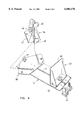
- FIG. 1 is a top perspective view of a universal lateral positioner according to the Prior Art
- FIG. 2 is a top perspective view of the hyperflexion plate in accordance with the invention in isometric projection to the universal lateral positioner of FIG. 1;
- FIG. 3 is a bottom perspective view of the hyperflexion plate of FIG. 2;
- FIG. 4 is a top perspective view of the hyperflexion plate attached to the universal lateral positioner of FIG. 1 with the anterior support plate of the universal lateral positioner of FIG. 1 in isometric projection to the attached hyperflexion plate;
- FIG. 5 is a top perspective view of two hyperflexion plates attached to the universal lateral positioner of FIG. 1 with the anterior and posterior position plates of the universal lateral positioner of FIG. 1 in isometric projection;
- FIG. 6 is a top perspective view of the anterior and posterior position plates of the universal lateral positioner plate of FIG. 1 attached to the two hyperflexion plates shown in FIG. 5.
- the positioner 10 is in the form of a support plate 11 made of an aluminum composition.
- the plate 11 is attached to an operating table, or the like, by means of a T-shaped fastener 12 arranged at one end.
- An elongated slot in the form of a track 13 extends along the major dimension of the plate 11 and serves to movably support the anterior or front support 16 as well as the posterior or back support indicated at 25.
- the anterior support 16 includes a front plate 17 on the bottom thereof that is movably attached to the track 13 by means of the threaded stem 19 extending from the knob 18.
- the vertical extension 17A formed on the anterior plate 17 serves to support first and second anterior pressure plates 20, 24 that provide the support function described in detail within the aforementioned U.S. Pat. No. 3,844,550.
- the height of the first anterior pressure plates can be adjusted by means of the arms 21A, 21B that attach to the vertical extension 17A by means of slot 23 and threaded knobs 22A, 22B.
- the posterior support 25 includes a posterior plate 29 on the bottom thereof that is movably attached to the track 13 by means of the threaded stem 28 extending from the knob 27.
- the vertical extension 29A formed on the posterior plate 29 serves to support the posterior pressure plate 26 that provide the support function as described within the aforementioned U.S. Pat. No. 3,844,550.
- a hyperflexion plate 30 is shown in Oils FIG. 2 in the form of a hexagonal plate 31 made of aluminum that includes a layer 31 A of Delrin on the bottom surface thereof along with a downwardly-extending rail 36 that is received in the track 13 on the support plate 11 shown earlier in FIG. 1 that carries the posterior support plate 25 and is attached to the track by means of the threaded stem 38 and knob 37.
- Delrin is a trade name of DuPont Inc. for an acetal homopolymer that can withstand sterilization treatment.
- the plate 31 includes opposing front and rear edges 32, 35 and opposing sides 33, 34 with a pair of additional tracks 39, 40 parallel with the sides 33, 34.
- the tracks 39, 40 are arranged at an angle equal to or greater than 45° relative to the rail 36 to allow positioning of the anterior pressure plates 20, 24 and posterior pressure plate 26 of FIG. 1 at a greater angle relative to the body of a patient as will be described below in some detail.
- the rear surface of the hyperflexion plate 30 is shown in FIG. 3 to include the Dehrin plate 31A to which the rail 36 is attached by screws, as indicated at 43.As now shown in FIG. 4, the hyperflexion plate 30 is first attached to the rail 13 on the support plate 11 of the universal lateral positioner 10 by means of the knob 37 to allow translation of the hyperflexion plate along the support plate.
- the first hyperflexion plate 30 is shown positioned on the support plate 11 with the anterior support assembly 16 in position thereon as shown in FIG. 4.
- a second hyperflexion plate 30' is arranged on the support plate 11 by insertion of the second rail 36' within the track 13 and adjusting the knob 37' accordingly.
- the posterior support plate 25 can optionally be positioned on the second hyperflexion plate 30' by insertion of the rail 42 on the posterior support plate within either of the second tracks 39', 40' on the second hyperflexion plate and adjusting the knob 27.
- the anterior support plate 16 can be directly attached to the support plate 11 and the posterior support plate 25 can be attached to the second hyperflexion plate 30' as shown in FIG. 6, if so desired. It is believed that the arrangement of the anterior and posterior plates on first and second hyperflexion plates provides the greatest variation in body positioning heretofore attainable.
- a body positioning arrangement for hip treatment and surgery has herein been described as including a first or second hyperflexion plate attached to a standard universal lateral positioner for increased flexion of the hip.
Landscapes
- Health & Medical Sciences (AREA)
- Engineering & Computer Science (AREA)
- Biomedical Technology (AREA)
- Life Sciences & Earth Sciences (AREA)
- Animal Behavior & Ethology (AREA)
- General Health & Medical Sciences (AREA)
- Public Health (AREA)
- Veterinary Medicine (AREA)
- Orthopedic Medicine & Surgery (AREA)
- Surgical Instruments (AREA)
Abstract
Description
Claims (16)
Priority Applications (1)
| Application Number | Priority Date | Filing Date | Title |
|---|---|---|---|
| US09/084,278 US6003176A (en) | 1998-05-26 | 1998-05-26 | Universal lateral positioner |
Applications Claiming Priority (1)
| Application Number | Priority Date | Filing Date | Title |
|---|---|---|---|
| US09/084,278 US6003176A (en) | 1998-05-26 | 1998-05-26 | Universal lateral positioner |
Publications (1)
| Publication Number | Publication Date |
|---|---|
| US6003176A true US6003176A (en) | 1999-12-21 |
Family
ID=22183933
Family Applications (1)
| Application Number | Title | Priority Date | Filing Date |
|---|---|---|---|
| US09/084,278 Expired - Lifetime US6003176A (en) | 1998-05-26 | 1998-05-26 | Universal lateral positioner |
Country Status (1)
| Country | Link |
|---|---|
| US (1) | US6003176A (en) |
Cited By (36)
| Publication number | Priority date | Publication date | Assignee | Title |
|---|---|---|---|---|
| US6305039B1 (en) * | 1997-07-12 | 2001-10-23 | Jenx Limited | Resting system |
| US6381782B2 (en) * | 2000-05-31 | 2002-05-07 | Kabushiki Kaisha Nihon M.D.M. | Body supporting tool for bed |
| US20030178027A1 (en) * | 2002-03-22 | 2003-09-25 | Edward Demayo | Lateral surgical positioner unit |
| US6701551B1 (en) | 2002-09-25 | 2004-03-09 | Steven J. Antinori | Upholstered slat box spring/bed |
| US20050076936A1 (en) * | 2003-10-08 | 2005-04-14 | Pung David John | Cleaning pad and cleaning implement |
| US20050081865A1 (en) * | 2003-10-17 | 2005-04-21 | Labelle Hubert | Dynamic frame for prone surgical positioning |
| US6932783B1 (en) * | 2004-10-30 | 2005-08-23 | James C. Donato | Passive hip reducer |
| US20070113349A1 (en) * | 2005-11-09 | 2007-05-24 | Oprandi Arthur V | Mattress pad |
| US20070123402A1 (en) * | 2005-11-30 | 2007-05-31 | Wayne Cantrell | Pelvic clamp for back stretching |
| US7415741B1 (en) * | 2006-01-12 | 2008-08-26 | Imp Inc. | Surgical patient positioner extension unit |
| US7426930B1 (en) * | 2006-05-22 | 2008-09-23 | Imp Inc. | Dual compression pad for surgical positioner units |
| US20100242177A1 (en) * | 2008-09-30 | 2010-09-30 | Composite Manufacturing, Inc. | Padded patient immobilizer for surgery tables |
| FR2946247A1 (en) * | 2009-06-08 | 2010-12-10 | Denis Pichon | Device for maintaining part i.e. hip, of body of patient in sidelying position on orthopedic surgical operation table, has shutter comprising axial sliding for allowing positioning of support part in locked position |
| US8132278B1 (en) * | 2010-01-04 | 2012-03-13 | Imp Inc. | Sterile operating table extension |
| US20140107393A1 (en) * | 2012-10-16 | 2014-04-17 | Aktina Corp. | Device for restraint of patients on a table |
| US20150094780A1 (en) * | 2012-06-18 | 2015-04-02 | MAQUET GmbH | Device for fixing a femur in hip endoprosthetics |
| US9149406B2 (en) | 2013-03-04 | 2015-10-06 | Robert Dan Allen | Trendelenburg patient restraint for surgery tables |
| US20180116891A1 (en) * | 2016-10-28 | 2018-05-03 | Warsaw Orthopedic, Inc | Surgical table and method for use thereof |
| US10548796B2 (en) | 2015-08-17 | 2020-02-04 | Warsaw Orthopedic, Inc. | Surgical frame and method for use thereof facilitating articulatable support for a patient during surgery |
| US10576006B2 (en) | 2017-06-30 | 2020-03-03 | Warsaw Orthopedic, Inc. | Surgical frame having translating lower beam and method for use thereof |
| US10835439B2 (en) | 2018-08-21 | 2020-11-17 | Warsaw Orthopedic, Inc. | Surgical frame having translating lower beam and moveable linkage or surgical equipment attached thereto and method for use thereof |
| US10842653B2 (en) | 2007-09-19 | 2020-11-24 | Ability Dynamics, Llc | Vacuum system for a prosthetic foot |
| US10874570B2 (en) | 2017-06-30 | 2020-12-29 | Warsaw Orthopedic, Inc. | Surgical frame and method for use thereof facilitating patient transfer |
| US10881570B2 (en) | 2019-04-26 | 2021-01-05 | Warsaw Orthopedic, Inc | Reconfigurable pelvic support for a surgical frame and method for use thereof |
| US10888484B2 (en) | 2019-04-26 | 2021-01-12 | Warsaw Orthopedic, Inc | Reconfigurable pelvic support for surgical frame and method for use thereof |
| US10893996B2 (en) | 2018-08-22 | 2021-01-19 | Warsaw Orthopedic, Inc. | Surgical frame having translating lower beam and moveable linkage or surgical equipment attached thereto and method for use thereof |
| US10900448B2 (en) | 2017-03-10 | 2021-01-26 | Warsaw Orthopedic, Inc. | Reconfigurable surgical frame and method for use thereof |
| US10898401B2 (en) | 2018-08-22 | 2021-01-26 | Warsaw Orthopedic, Inc. | Reconfigurable surgical frame and method for use |
| US10966892B2 (en) | 2015-08-17 | 2021-04-06 | Warsaw Orthopedic, Inc. | Surgical frame facilitating articulatable support for a patient during surgery |
| US11007104B2 (en) | 2017-08-17 | 2021-05-18 | Steven T. Woolson | Frame and method for positioning a patient undergoing hip surgery |
| US11020304B2 (en) | 2017-08-08 | 2021-06-01 | Warsaw Orthopedic, Inc. | Surgical frame including main beam for facilitating patient access |
| US11234886B2 (en) | 2019-09-25 | 2022-02-01 | Warsaw Orthopedic, Inc. | Reconfigurable upper leg support for a surgical frame |
| US11304867B2 (en) | 2020-04-22 | 2022-04-19 | Warsaw Orthopedic, Inc. | Lift and method for use of a lift for positioning a patient relative to a surgical frame |
| US11744758B2 (en) | 2020-02-03 | 2023-09-05 | Alphatec Spine, Inc. | Patient positioning system |
| US11813217B2 (en) | 2020-04-22 | 2023-11-14 | Warsaw Orthopedic, Inc | Lift and method for use of a lift for positioning a patient relative to a surgical frame |
| US11925586B2 (en) | 2022-03-25 | 2024-03-12 | Mazor Robotics Ltd. | Surgical platform and trolley assembly |
Citations (2)
| Publication number | Priority date | Publication date | Assignee | Title |
|---|---|---|---|---|
| US4866796A (en) * | 1985-04-17 | 1989-09-19 | Thomas J. Ring | Therapeutic table |
| US5390383A (en) * | 1993-11-15 | 1995-02-21 | Sunmed, Inc. | Anterior pelvic support device for a surgery patient |
-
1998
- 1998-05-26 US US09/084,278 patent/US6003176A/en not_active Expired - Lifetime
Patent Citations (2)
| Publication number | Priority date | Publication date | Assignee | Title |
|---|---|---|---|---|
| US4866796A (en) * | 1985-04-17 | 1989-09-19 | Thomas J. Ring | Therapeutic table |
| US5390383A (en) * | 1993-11-15 | 1995-02-21 | Sunmed, Inc. | Anterior pelvic support device for a surgery patient |
Cited By (55)
| Publication number | Priority date | Publication date | Assignee | Title |
|---|---|---|---|---|
| US6305039B1 (en) * | 1997-07-12 | 2001-10-23 | Jenx Limited | Resting system |
| US6381782B2 (en) * | 2000-05-31 | 2002-05-07 | Kabushiki Kaisha Nihon M.D.M. | Body supporting tool for bed |
| US20030178027A1 (en) * | 2002-03-22 | 2003-09-25 | Edward Demayo | Lateral surgical positioner unit |
| US6820621B2 (en) * | 2002-03-22 | 2004-11-23 | Imp Inc. | Lateral surgical positioner unit |
| US6701551B1 (en) | 2002-09-25 | 2004-03-09 | Steven J. Antinori | Upholstered slat box spring/bed |
| US20050076936A1 (en) * | 2003-10-08 | 2005-04-14 | Pung David John | Cleaning pad and cleaning implement |
| US20050081865A1 (en) * | 2003-10-17 | 2005-04-21 | Labelle Hubert | Dynamic frame for prone surgical positioning |
| US6941951B2 (en) * | 2003-10-17 | 2005-09-13 | Labelle Hubert | Dynamic frame for prone surgical positioning |
| US6932783B1 (en) * | 2004-10-30 | 2005-08-23 | James C. Donato | Passive hip reducer |
| US20070113349A1 (en) * | 2005-11-09 | 2007-05-24 | Oprandi Arthur V | Mattress pad |
| US20070123402A1 (en) * | 2005-11-30 | 2007-05-31 | Wayne Cantrell | Pelvic clamp for back stretching |
| US8784279B2 (en) * | 2005-11-30 | 2014-07-22 | Wayne Cantrell | Pelvic clamp for back stretching |
| US7415741B1 (en) * | 2006-01-12 | 2008-08-26 | Imp Inc. | Surgical patient positioner extension unit |
| US7426930B1 (en) * | 2006-05-22 | 2008-09-23 | Imp Inc. | Dual compression pad for surgical positioner units |
| US10842653B2 (en) | 2007-09-19 | 2020-11-24 | Ability Dynamics, Llc | Vacuum system for a prosthetic foot |
| US20100242177A1 (en) * | 2008-09-30 | 2010-09-30 | Composite Manufacturing, Inc. | Padded patient immobilizer for surgery tables |
| FR2946247A1 (en) * | 2009-06-08 | 2010-12-10 | Denis Pichon | Device for maintaining part i.e. hip, of body of patient in sidelying position on orthopedic surgical operation table, has shutter comprising axial sliding for allowing positioning of support part in locked position |
| US8132278B1 (en) * | 2010-01-04 | 2012-03-13 | Imp Inc. | Sterile operating table extension |
| US20150094780A1 (en) * | 2012-06-18 | 2015-04-02 | MAQUET GmbH | Device for fixing a femur in hip endoprosthetics |
| US10159520B2 (en) * | 2012-06-18 | 2018-12-25 | Mquet Gmbh | Device for fixing a femur for hip endoprosthesis surgery |
| US20140107393A1 (en) * | 2012-10-16 | 2014-04-17 | Aktina Corp. | Device for restraint of patients on a table |
| US9254217B2 (en) * | 2012-10-16 | 2016-02-09 | Aktina Corp. | Device for restraint of patients on a table |
| US9149406B2 (en) | 2013-03-04 | 2015-10-06 | Robert Dan Allen | Trendelenburg patient restraint for surgery tables |
| US10245201B2 (en) | 2013-03-04 | 2019-04-02 | Robert Dan Allen | Trendelenburg patient restraint for surgery tables |
| US11957626B2 (en) | 2015-08-17 | 2024-04-16 | Warsaw Orthopedic, Inc. | Surgical frame and method for use thereof facilitating articulatable support for a patient during surgery |
| US10548796B2 (en) | 2015-08-17 | 2020-02-04 | Warsaw Orthopedic, Inc. | Surgical frame and method for use thereof facilitating articulatable support for a patient during surgery |
| US10751240B2 (en) | 2015-08-17 | 2020-08-25 | Warsaw Orthopedic, Inc. | Surgical frame and method for use thereof facilitating articulatable support for a patient during surgery |
| US11612533B2 (en) | 2015-08-17 | 2023-03-28 | Warsaw Orthopedic, Inc. | Surgical frame facilitating articulatable support for a patient during surgery |
| US10966892B2 (en) | 2015-08-17 | 2021-04-06 | Warsaw Orthopedic, Inc. | Surgical frame facilitating articulatable support for a patient during surgery |
| US20180116891A1 (en) * | 2016-10-28 | 2018-05-03 | Warsaw Orthopedic, Inc | Surgical table and method for use thereof |
| US10940072B2 (en) * | 2016-10-28 | 2021-03-09 | Warsaw Orthopedic, Inc. | Surgical table and method for use thereof |
| US11857467B2 (en) * | 2016-10-28 | 2024-01-02 | Warsaw Orthopedic, Inc. | Surgical table and method for use thereof |
| US20210145685A1 (en) * | 2016-10-28 | 2021-05-20 | Warsaw Orthopedic, Inc. | Surgical table and method for use thereof |
| US10900448B2 (en) | 2017-03-10 | 2021-01-26 | Warsaw Orthopedic, Inc. | Reconfigurable surgical frame and method for use thereof |
| US10576006B2 (en) | 2017-06-30 | 2020-03-03 | Warsaw Orthopedic, Inc. | Surgical frame having translating lower beam and method for use thereof |
| US11052008B2 (en) | 2017-06-30 | 2021-07-06 | Warsaw Orthopedic, Inc. | Surgical frame and method for use thereof facilitating patient transfer |
| US10874570B2 (en) | 2017-06-30 | 2020-12-29 | Warsaw Orthopedic, Inc. | Surgical frame and method for use thereof facilitating patient transfer |
| US11389362B2 (en) | 2017-06-30 | 2022-07-19 | Warsaw Orthopedic, Inc. | Surgical frame having translating lower beam and method for use thereof |
| US11020304B2 (en) | 2017-08-08 | 2021-06-01 | Warsaw Orthopedic, Inc. | Surgical frame including main beam for facilitating patient access |
| US11819461B2 (en) | 2017-08-08 | 2023-11-21 | Warsaw Orthopedic, Inc. | Surgical frame including main beam for facilitating patient access |
| US11007104B2 (en) | 2017-08-17 | 2021-05-18 | Steven T. Woolson | Frame and method for positioning a patient undergoing hip surgery |
| US10835439B2 (en) | 2018-08-21 | 2020-11-17 | Warsaw Orthopedic, Inc. | Surgical frame having translating lower beam and moveable linkage or surgical equipment attached thereto and method for use thereof |
| US11696863B2 (en) | 2018-08-21 | 2023-07-11 | Warsaw Orthopedic, Inc. | Surgical frame having translating lower beam and moveable linkage or surgical equipment attached thereto and method for use thereof |
| US11624342B2 (en) | 2018-08-22 | 2023-04-11 | Warsaw Orthopedic, Inc. | Reconfigurable surgical frame and method for use thereof |
| US10893996B2 (en) | 2018-08-22 | 2021-01-19 | Warsaw Orthopedic, Inc. | Surgical frame having translating lower beam and moveable linkage or surgical equipment attached thereto and method for use thereof |
| US10898401B2 (en) | 2018-08-22 | 2021-01-26 | Warsaw Orthopedic, Inc. | Reconfigurable surgical frame and method for use |
| US10881570B2 (en) | 2019-04-26 | 2021-01-05 | Warsaw Orthopedic, Inc | Reconfigurable pelvic support for a surgical frame and method for use thereof |
| US11369538B2 (en) | 2019-04-26 | 2022-06-28 | Warsaw Orthopedic, Inc. | Reconfigurable pelvic support for a surgical frame and method for use thereof |
| US10888484B2 (en) | 2019-04-26 | 2021-01-12 | Warsaw Orthopedic, Inc | Reconfigurable pelvic support for surgical frame and method for use thereof |
| US11672718B2 (en) | 2019-09-25 | 2023-06-13 | Warsaw Orthopedic, Inc. | Reconfigurable upper leg support for a surgical frame |
| US11234886B2 (en) | 2019-09-25 | 2022-02-01 | Warsaw Orthopedic, Inc. | Reconfigurable upper leg support for a surgical frame |
| US11744758B2 (en) | 2020-02-03 | 2023-09-05 | Alphatec Spine, Inc. | Patient positioning system |
| US11813217B2 (en) | 2020-04-22 | 2023-11-14 | Warsaw Orthopedic, Inc | Lift and method for use of a lift for positioning a patient relative to a surgical frame |
| US11304867B2 (en) | 2020-04-22 | 2022-04-19 | Warsaw Orthopedic, Inc. | Lift and method for use of a lift for positioning a patient relative to a surgical frame |
| US11925586B2 (en) | 2022-03-25 | 2024-03-12 | Mazor Robotics Ltd. | Surgical platform and trolley assembly |
Similar Documents
| Publication | Publication Date | Title |
|---|---|---|
| US6003176A (en) | Universal lateral positioner | |
| US6311349B1 (en) | Pelvic positioner | |
| US6820621B2 (en) | Lateral surgical positioner unit | |
| US3823709A (en) | Table supported surgical retractor and pelvic support | |
| US6941951B2 (en) | Dynamic frame for prone surgical positioning | |
| US9554959B2 (en) | Anterior pelvic support device for a surgery patient | |
| US5390383A (en) | Anterior pelvic support device for a surgery patient | |
| US6154901A (en) | Spinal-surgery table | |
| US2691979A (en) | Anchor for unilateral traction | |
| US6214004B1 (en) | Vertebral triplaner alignment facilitator | |
| US5063918A (en) | Multi-mode distraction system for ankle arthroscopy | |
| US4428571A (en) | Limb positioning device | |
| JP2638398B2 (en) | Endoprosthesis for hip bone | |
| US4443005A (en) | Foot support device | |
| DEWALD et al. | Skeletal traction for the treatment of severe scoliosis: the University of Illinois halo-hoop apparatus | |
| US4995067A (en) | Surgical and x-ray operation table extension | |
| US6984066B2 (en) | Attachable surgical table | |
| US20070089239A1 (en) | Surgical fixture device and method for supporting a patient during surgery | |
| US20210321997A1 (en) | Robot-mounted retractor system | |
| WO2009062545A1 (en) | Modular device for positioning and immobilisation of a patient's body for surgical operations and corresponding operating table | |
| US11399870B2 (en) | Automatic traction device for lower limb fracture osteosynthesis | |
| US20170216122A1 (en) | Modular patient positioning system | |
| WO1996025891A1 (en) | Articulating external fixation device | |
| US20180256428A1 (en) | Hip positioner system and arm assembly | |
| JP7237174B2 (en) | Hip or knee surgical leg retainer and method of placement |
Legal Events
| Date | Code | Title | Description |
|---|---|---|---|
| AS | Assignment |
Owner name: IMP INC., CONNECTICUT Free format text: ASSIGNMENT OF ASSIGNORS INTEREST;ASSIGNORS:WALSEY, ALAN A.;BAILEY, JAMES R.;RITLAND, G. DAVID;REEL/FRAME:009381/0649;SIGNING DATES FROM 19980508 TO 19980518 |
|
| FPAY | Fee payment |
Year of fee payment: 4 |
|
| REMI | Maintenance fee reminder mailed | ||
| FEPP | Fee payment procedure |
Free format text: PETITION RELATED TO MAINTENANCE FEES FILED (ORIGINAL EVENT CODE: PMFP); ENTITY STATUS OF PATENT OWNER: SMALL ENTITY |
|
| FEPP | Fee payment procedure |
Free format text: PETITION RELATED TO MAINTENANCE FEES FILED (ORIGINAL EVENT CODE: PMFP); ENTITY STATUS OF PATENT OWNER: SMALL ENTITY |
|
| FEPP | Fee payment procedure |
Free format text: PETITION RELATED TO MAINTENANCE FEES GRANTED (ORIGINAL EVENT CODE: PMFG); ENTITY STATUS OF PATENT OWNER: SMALL ENTITY |
|
| REIN | Reinstatement after maintenance fee payment confirmed | ||
| FP | Lapsed due to failure to pay maintenance fee |
Effective date: 20071221 |
|
| FPAY | Fee payment |
Year of fee payment: 8 |
|
| SULP | Surcharge for late payment | ||
| PRDP | Patent reinstated due to the acceptance of a late maintenance fee |
Effective date: 20080514 |
|
| STCF | Information on status: patent grant |
Free format text: PATENTED CASE |
|
| REMI | Maintenance fee reminder mailed | ||
| FPAY | Fee payment |
Year of fee payment: 12 |
|
| SULP | Surcharge for late payment |
Year of fee payment: 11 |
|
| FEPP | Fee payment procedure |
Free format text: PAYOR NUMBER ASSIGNED (ORIGINAL EVENT CODE: ASPN); ENTITY STATUS OF PATENT OWNER: SMALL ENTITY |
|
| AS | Assignment |
Owner name: INNOVATIVE MEDICAL PRODUCTS, INC., CONNECTICUT Free format text: NUNC PRO TUNC ASSIGNMENT;ASSIGNORS:IMP INC.;IMP, INC.;I MP INC.;REEL/FRAME:032952/0745 Effective date: 20140522 |