US5970184A - Laser beam generation control system for optical bar code scanner - Google Patents
Laser beam generation control system for optical bar code scanner Download PDFInfo
- Publication number
- US5970184A US5970184A US08/971,571 US97157197A US5970184A US 5970184 A US5970184 A US 5970184A US 97157197 A US97157197 A US 97157197A US 5970184 A US5970184 A US 5970184A
- Authority
- US
- United States
- Prior art keywords
- laser beam
- laser
- bar code
- generation
- scanning
- Prior art date
- Legal status (The legal status is an assumption and is not a legal conclusion. Google has not performed a legal analysis and makes no representation as to the accuracy of the status listed.)
- Expired - Lifetime
Links
Images


Classifications
-
- G—PHYSICS
- G06—COMPUTING; CALCULATING OR COUNTING
- G06K—GRAPHICAL DATA READING; PRESENTATION OF DATA; RECORD CARRIERS; HANDLING RECORD CARRIERS
- G06K7/00—Methods or arrangements for sensing record carriers, e.g. for reading patterns
- G06K7/10—Methods or arrangements for sensing record carriers, e.g. for reading patterns by electromagnetic radiation, e.g. optical sensing; by corpuscular radiation
- G06K7/10544—Methods or arrangements for sensing record carriers, e.g. for reading patterns by electromagnetic radiation, e.g. optical sensing; by corpuscular radiation by scanning of the records by radiation in the optical part of the electromagnetic spectrum
- G06K7/10821—Methods or arrangements for sensing record carriers, e.g. for reading patterns by electromagnetic radiation, e.g. optical sensing; by corpuscular radiation by scanning of the records by radiation in the optical part of the electromagnetic spectrum further details of bar or optical code scanning devices
- G06K7/10861—Methods or arrangements for sensing record carriers, e.g. for reading patterns by electromagnetic radiation, e.g. optical sensing; by corpuscular radiation by scanning of the records by radiation in the optical part of the electromagnetic spectrum further details of bar or optical code scanning devices sensing of data fields affixed to objects or articles, e.g. coded labels
- G06K7/10871—Methods or arrangements for sensing record carriers, e.g. for reading patterns by electromagnetic radiation, e.g. optical sensing; by corpuscular radiation by scanning of the records by radiation in the optical part of the electromagnetic spectrum further details of bar or optical code scanning devices sensing of data fields affixed to objects or articles, e.g. coded labels randomly oriented data-fields, code-marks therefore, e.g. concentric circles-code
-
- G—PHYSICS
- G06—COMPUTING; CALCULATING OR COUNTING
- G06K—GRAPHICAL DATA READING; PRESENTATION OF DATA; RECORD CARRIERS; HANDLING RECORD CARRIERS
- G06K7/00—Methods or arrangements for sensing record carriers, e.g. for reading patterns
- G06K7/10—Methods or arrangements for sensing record carriers, e.g. for reading patterns by electromagnetic radiation, e.g. optical sensing; by corpuscular radiation
- G06K7/10544—Methods or arrangements for sensing record carriers, e.g. for reading patterns by electromagnetic radiation, e.g. optical sensing; by corpuscular radiation by scanning of the records by radiation in the optical part of the electromagnetic spectrum
- G06K7/10554—Moving beam scanning
- G06K7/10564—Light sources
- G06K7/10584—Source control
-
- G—PHYSICS
- G06—COMPUTING; CALCULATING OR COUNTING
- G06K—GRAPHICAL DATA READING; PRESENTATION OF DATA; RECORD CARRIERS; HANDLING RECORD CARRIERS
- G06K7/00—Methods or arrangements for sensing record carriers, e.g. for reading patterns
- G06K7/10—Methods or arrangements for sensing record carriers, e.g. for reading patterns by electromagnetic radiation, e.g. optical sensing; by corpuscular radiation
- G06K7/10544—Methods or arrangements for sensing record carriers, e.g. for reading patterns by electromagnetic radiation, e.g. optical sensing; by corpuscular radiation by scanning of the records by radiation in the optical part of the electromagnetic spectrum
- G06K7/10821—Methods or arrangements for sensing record carriers, e.g. for reading patterns by electromagnetic radiation, e.g. optical sensing; by corpuscular radiation by scanning of the records by radiation in the optical part of the electromagnetic spectrum further details of bar or optical code scanning devices
- G06K7/10851—Circuits for pulse shaping, amplifying, eliminating noise signals, checking the function of the sensing device
-
- G—PHYSICS
- G06—COMPUTING; CALCULATING OR COUNTING
- G06K—GRAPHICAL DATA READING; PRESENTATION OF DATA; RECORD CARRIERS; HANDLING RECORD CARRIERS
- G06K2207/00—Other aspects
- G06K2207/1012—Special detection of object
-
- G—PHYSICS
- G06—COMPUTING; CALCULATING OR COUNTING
- G06K—GRAPHICAL DATA READING; PRESENTATION OF DATA; RECORD CARRIERS; HANDLING RECORD CARRIERS
- G06K2207/00—Other aspects
- G06K2207/1018—Source control
Definitions
- the present invention relates to a laser beam generation control system for an optical mark scanner device, and particularly to a laser beam generation control system for an optical mark scanner which can shorten a generation period of a laser beam thereby to prolong a laser diode's life.
- a laser diode has the advantage that it can be miniaturized in comparison with a helium-neon laser oscillator and can be driven with a low consumption of power, attention is now directed to the life of the laser diode. That is, the life of the laser diode is relatively shorter, and is dependent on a generation time or a burning time and it is necessary to substitute a new laser diode at regular intervals.
- An optical mark reader device such as a bar-code scanner is an input device that illuminates the bar code symbols on tags or products and then detects the reflected light from the bar code symbol.
- the scanner is passed across the code or the object containing the code is passed across the scanner.
- Fixed-beam scanners are used to monitor the movement of materials.
- the laser diode is turned on only when a bar code is read, and a generation period of the laser thereby is shorted to prolong its life. That is, when the bar code is read, the generation of the laser is generally stopped, and when an article which is passed into a reading space is detected by an optical sensor, which is regarded as an item sensor or an article sensor, or when a reading operation is turned ON, the laser diode is turned ON, thereby to shorten the laser generation time of the laser diode and prolong the life thereof.
- a laser beam generation control system for an optical mark scanner device including a laser generation element, a laser generation control unit, a laser scanner unit for scanning a mark such as a bar code and a signal processor unit for photoconverting a reflected light from the mark thereby to read same, wherein the laser beam generation control unit turns ON/OFF the laser generation element in accordance with a predetermined duty cycle, thereby to carry out the generation of the laser beam intermittently.
- FIG. 1 is a block diagram for explaining an operation of an embodiment, in accordance with the present invention.
- FIG. 2 is a general view showing a construction of a bar code scanner of the present invention
- FIGS. 3(A) and 3(B) show a view explaining a barcode scanning unit having a polygonal mirror
- FIG. 4 shows a diagram for explaining a first embodiment of the laser beam generation control unit 14
- FIG. 5 is a waveform diagram of a signal PNF in FIG. 4;
- FIG. 6 is a diagram for explaining a second embodiment of the laser beam generation control unit
- FIG. 7 is a waveform diagram showing the operation of each part of FIG. 6;
- FIG. 8 is a view showing a detecting condition of the bar code
- FIG. 9 is a block diagram of a third embodiment of the laser beam generation control unit 14.
- FIG. 10 is a timing chart of the operation of each part in FIG. 9;
- FIG. 11 is a waveform diagram showing a starting performance in FIG. 9;
- FIG. 12 is a block diagram of a fourth embodiment of the laser beam generation control unit
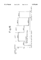
- FIG. 13 is a timing chart diagram of the operation of FIG. 12.
- FIG. 14 is a schematic of an automatic power control circuit in the laser beam generation control unit in FIG. 2;
- FIG. 15 is a schematic of a laser turn-ON inhibition circuit in FIG. 2;
- FIG. 16 is a timing chart showing a laser diode control method according to a duty cycle drive control system in accordance with the present invention.
- FIG. 1 is a block diagram for explaining an operation of an embodiment of the present invention.
- Reference numeral 11 denotes an article, 12 a bar code affixed to or printed on the article, 13 a laser scanner for scanning a bar code with a laser, beam, 14 a laser beam generation control unit for controlling the generation of the laser beam by unit 13, 16 a photodetector for carrying out a photoelectric conversion of a reflected laser light beam from the bar code 12, 17 a binary coded circuit unit for binary-coding an output of the photodetector 16, and 18 a signal processor unit for demodulating the bar code data output of the binary coded circuit unit 17 and controlling the whole device.
- the laser beam generation control unit 14 includes a laser beam control signal generator 14a, an ON-OFF signal generator unit 14b for generating a pulse signal PNF having a predetermined duty cycle, and a timer (“TIMER T1") 14c.
- the mode of operation of the apparatus in FIG. 1 is as follows.
- the laser beam generation control unit 14 turns ON/OFF a laser beam generation element in the laser scanner 13 in accordance with a predetermined duty cycle thereby to cause unit 13 to generate a laser beam intermittently. If the duty cycle is 50%, the generation period is one-half the time period of a continuous generation period, and thereby doubles the life.
- the laser beam generation control unit 14 also turns ON/OFF the laser beam control signal generation unit 14a to generate a laser beam intermittently such that when a detection of a reflected light from the bar code 12 during an intermittent beam generation is discriminated by the photodetector 16, the binary-coded circuit unit 17 and the signal processor unit 18, the laser beam generation element is turned ON thereby to generate a laser beam continuously, whereas when a reflected light from the bar code 12 is not detected for more than a predetermined period of time during a period, or interval, of continuous beam generation, the laser beam generation is switched to intermittent generation.
- the laser beam generation time period is reduced, while the continuous laser beam generation enables the reading of a bar code accurately, which is advantageous when articles arrive continuously for scanning.
- the laser beam generation control unit 14 does not detect a reflected light from a mark or a bar code for more than a predetermined period of time during a continuous generation of the laser beam, it is switched to an intermittent generation, whereas when it does not detect a reflected light from a mark for more than a predetermined period of time during an intermittent generation of the laser beam, the generation of the laser beam is stopped.
- a power source is not turned OFF at the end of a work period, if the work is finished, or if the device is not being activated such as when customers are scarce, the laser automatically stops generating a beam, thereby to prolong the life thereof.
- the operation of a motor or a mark reading portion can be stopped (that is, a power source is turned OFF) to reduce power consumption.
- FIG. 2 is a general view showing a construction of a bar code scanner of the present invention.
- reference numeral 11 denotes an article
- 12 a bar code affixed to or printed on the article
- 13 a laser beam scanner for scanning a bar code with a laser beam
- 14 a laser beam generation control unit for controlling the generation of a laser beam
- 15 a convergence unit for collecting a reflected laser light beam from a bar code
- 16 a photodetector for converting the light beam collected in the collector unit into an electrical signal
- 17 a binary-coded circuit unit for binary-coding an output of the photodetector
- 18 a signal processor unit for demodulating the binary-coded output of unit 17 and controlling the whole device
- 19 an operating unit
- the laser beam scanner unit 13 includes a laser diode 13a generating a laser beam, a laser diode drive unit 13b turning ON/OFF a laser diode by a laser control signal RLT, a scanning optical system 13c for scanning a laser beam on a bar code surface by a rotation operation thereof, a motor 13d for rotating the scanning optical system 13c, and a motor drive circuit 13e.
- FIGS. 3(A) and 3(B) are diagrams for explaining a bar code scanning unit.
- the laser beam scanning optical system 13c includes a polygonal mirror 13c-1 and a reflection mirror 13c-2 forming a scanning pattern.
- a laser beam RB is reflected by the polygon mirror 13c-1, rotated by the motor 13d, and the reflection mirror 13c-2 thereby to scan the bar code surface 12 with a laser beam scanning pattern as shown in FIG. 3(B) by means of only the on rotating mirror 13c-1.
- the pattern is regarded as a scanning pattern.
- a first embodiment of the laser bean generation control unit 14 will be described as follows.
- FIG. 4 shows a view explaining a first embodiment of the laser beam generation control unit 14.
- FIG. 5 is a waveform diagram of a signal PNF produced in unit 14.
- the laser bean generation control unit 14 includes a laser beam control signal generation unit 14a and an ON/OFF signal generator unit 14b generating a pulse signal PNF for turning ON/OFF the unit 14a in accordance with a predetermined duty cycle.
- the ON/OFF signal generator unit 14b generates a pulse signal PNF having an ON-time t 2 and an OFF-time t 1 , as shown in FIG.
- the ON-time t 2 is more than a period of the scanning pattern, viz., more than the period of one rotation of the polygonal mirror 13c;
- the duty cycle may be, for example, 50%, and the period of a pulse signal PNF is considerably shorter than the period, or time interval, in which an article is passed through a read space and is, preferably, equal to one up to several such periods.
- the signal processor unit 18 When a read activation switch (not shown in the figure) on the operation unit 19 of FIG. 2 is operated (i.e., actuated), the signal processor unit 18 generates a motor drive signal MST to drive the motor 13d in rotation and at the same time to control a voltage supply circuit 21 to apply a voltage E to the amplifier 17a and the binary-coded circuit 17b in the binary-coded circuit unit 17 and, further, a read start[ing] instruction RST which is input to the laser beam generation control unit 14.
- the laser beam control signal generation unit 14a inputs the ON/OFF signal PNF produced by the ON/OFF signal generation unit 14b to the laser diode drive unit 13b (Refer to FIG. 2) intact, as the laser control signal RLT.
- the laser diode drive unit 13b turns ON/OFF the laser diode 13a to scan the bar code 12 of incoming articles with the laser beam.
- a reflected light beam from the bar code 12 is converged on the convergence unit 15, and photoconverted by the photodetector 16, and thereafter binary-coded by the binary-coded circuit unit 17 and thereafter is input to the signal processor unit 18.
- the signal processor unit 18 demodulates the bar code based on the binary-coded output of unit 17b, thereby to output the bar code data. Thereafter, whenever an article arrives thereat, the above-described read operation is carried out.
- a read termination signal RSP and a motor stopping signal MSP are output from the signal processor unit 19, the laser beam generation control unit 14 sets the laser control signal RLT at a LOW level to stop the generation of the laser beam and the motor stops rotating.
- the device may be constituted such that the ON/OFF duty cycle, in the case where an intermittent phenomena occurs, is reduced gradually.
- the duty cycle is made 100% (a continuous generation), thereafter it is reduced in successive amounts such as to 90%, to 80%, to 70%, to 60%, to 50%, to 40%, to 30%, to 20%, and to 10%--and, when a reflected light is detected from the bar code, it returns to 100%.
- FIG. 6 is a block diagram showing a second embodiment of the laser beam generation control unit in accordance with the present invention.
- the laser beam generation control unit 14 includes a laser beam control signal generation unit 14a for outputting a laser control signal RLT, an ON/OFF signal generation unit 14b for generating a pulse signal PNF, for carrying out an ON/OFF operation in accordance with a predetermined duty cycle, and a timer 14c for counting a first predetermined time interval T 1 (i.e., a continuous generation period).
- the ON/OFF signal generation unit 14b produces a pulse signal PNF having an ON time t 2 and an OFF time t 1 and preferably, the ON time t 2 is more than one period of scanning pattern, that is, a period of more than one rotation of a polygonal mirror 13c.
- the ON time t 2 is set considerably shorter than the OFF time t 1 .
- the laser beam generation control unit 14 turns ON/OFF the laser diode 13a to produce a laser beam intermittently; (2) when a reflected light from the bar code 12 is detected during an intermittent interval of the laser beam generation, the laser diode is turned ON to produce a laser beam continuously; and (3) when a reflected light from the bar code is not detected for more than a predetermined time during an interval of continuous beam generation, the device 14 is switched to a state of intermittent generation as to the control of the generation of the laser beam.
- the operation of the laser beam generation control unit 14 is as follows.
- the signal processor unit 1 When a read activation switch (not shown) in the operation unit 19 (FIG. 2) is operated, the signal processor unit 1 generates a motor drive signal MST to drive the motor 13d in rotation and at the same time controls a voltage supply circuit 21 to apply a voltage E to an amplifier 17a and a binary-coded circuit 17b in the binary-coded circuit unit 17, and a read start[ing] instruction signal RST is input to the laser beam generation control unit 14.
- the laser beam control signal generation unit 14a inputs an ON/OFF signal PNF, produced by the ON/OFF signal generation unit 14b, to the laser diode drive unit 13b (FIG. 2) intact, as the laser control signal RLT.
- the laser diode drive unit 13b turns ON/OFF the laser diode 13a to scan the bar code 12 of incoming articles by the laser beam.
- a reflected light beam from the bar code 12 is converged in the convergence unit 15, photoconverted by the photodetector 16, and thereafter binary-coded by the binary-coded circuit unit 17 and supplied as an input to the signal processor unit 18.
- FIG. 8 is a diagram showing a detecting condition of the bar code.
- a UPC type bar code has margins M1 and M2 at opposite ends of the bar code and four bars (black-white-black-white) LB and RB are provided adjacent to the respective margins M1 and M2, a center bar CB, at the center, and four to six characters of the bar codes which are inserted in a first half part between bars LB and CB and a second half part between bars CB and RB, respectively.
- a binary-coded signal is produced (FIG. 8(B)).
- the signal processor unit 18 monitors whether or not a binary-coded signal that satisfies the above expressions is input and, when input, it outputs a bar code-during-reading signal BRI.
- the bar code-during-reading signal BRI is input, the laser beam control signal generation unit 14a is switched from a state of intermittent generation to and maintained thereafter in a state of continuous generation.
- the bar code is read and when a concise reading of the bar code is completed, or a setup time has elapsed, the bar code-during-reading signal BRI is removed (i.e., terminated).
- the laser beam control signal generation unit 14a inputs a time counting start instruction TST1 to the timer 14c and causes the timer 14c to start counting.
- the timer 14c when a time T 1 is counted without the bar code-during-reading signal BRI being input, the timer 14c outputs a time-up signal TUP1.
- the laser beam control signal generation unit 14a When the time-up signal TUP1 is produced, the laser beam control signal generation unit 14a outputs an ON/OFF signal PNF, which is produced and output by the ON/OFF signal generation unit 14b, as a laser control signal RLT and switches from a state of continuous generation to a state of intermittent generation. Thereafter, the same laser beam generation control is carried out.
- counting of the timer 14c is reset.
- a read termination signal RSP and a motor stopping signal MSP are output from the signal processor unit 19 and the laser beam generation control unit 14 sets the laser control signal RLT to a LOW level, thereby to stop the generation of the laser and to stop the driving of the motor, which then stops rotating.
- a third embodiment of the laser beam generation control unit 14 is described as follows.
- FIG. 9 is a block diagram explaining a third embodiment of the laser beam generation control unit 14 of the present invention.
- the laser beam generation control unit 14 includes a laser beam control signal generation unit 14a outputting a laser beam control signal RLT, an ON/OFF signal generation unit 14b outputting a pulse signal PNF which turns ON/OFF by a predetermined duty cycle, a timer 14c counting a first predetermined time T 1 (continuous generation time period) and a timer 14d counting a second time T 2 (a laser generation stoppage time period). It is preferable that the ON time t 2 of an ON/OFF signal PNF output from the ON/OFF signal generation unit 14b has a period greater than the period of a scanning pattern, i.e., a period more than that of one rotation of the polygonal mirror 13c.
- the laser beam generation control unit 14 turns ON/OFF he laser diode 13a to produce a laser beam intermittently; (2) when detecting a reflected light from the bar code during an intermittent generation, the unit 14 turns ON the laser diode to carry out a laser generation continuously; (3) when the unit 14 does not detect a reflected light from the bar code for more than a first time T 1 during a continuous generation, the unit 14 is switched to a state of intermittent generation; and (4) when the unit 14 does not detect a reflected light from the bar code for more than a second time T 2 during an intermittent generation, it stops the generation of the laser beam.
- the operation of the laser beam generation control unit 14 is as follows.
- the signal processor unit 18 When a read activation switch (not shown in the figure) in the operation unit 19 is operated, the signal processor unit 18 generates a motor drive signal MST to make the motor 13d rotate and at the same time controls the voltage supply circuit 21 to apply a voltage E to an amplifier 17a and a binary-coded circuit 17b in the binary-coded circuit-unit 17 and then a read start instruction signal RST is input to the laser beam generation control unit 14.
- the laser beam control signal generation unit 14a inputs an ON/OFF signal PNF produced from the ON/OFF signal generations unit 14b to the laser diode drive unit 13b intact as the laser control signal RLT (Refer to FIG. 10).
- the laser diode drive unit 13b turns ON/OFF the laser diode 13a to scan the barcode 12 of the presented articles by the laser beam.
- a reflected light from the barcode 12 is converged in the convergence unit 15, photoconverted by the photodetector 16 and thereafter binary-coded by the binary-coded circuit unit 17 and input thereby to the signal processor unit 18.
- the signal processor unit 18 monitors whether or not the bar code is detected, based on the binary-coded output and, when detected, the bar code-during-reading signal BRI is output.
- the laser beam control signa generation unit 14a is switched from a state of intermittent generation to, and maintained in, a state of continuous generation.
- the laser beam control signal generation unit 14a inputs a time counting start instruction TST1 to the timer 14c to start the timer.
- the timer 14c outputs a time-up signal TUP1.
- the laser beam control signal generation unit 14a outputs an ON/OFF signal PNF, generated and output by the ON/OFF signal generation unit 14b, as a laser control signal RLT and thereby switches from a state of continuous generation to a state of intermittent generation.
- the laser beam control signal generation unit 14a then inputs a count start instructions TST2 to the timer 14d to start it counting.
- the time-up signal TUP2 is output.
- the laser beam control signal generation unit 14a sets the laser control signal RLT at a LOW level to stop the generation of a laser beam and at the same time outputs a power source OFF instruction POF to the signal processor unit 18, the motor or the like thereupon stops rotating and the voltage supply to the binary-coded circuit unit 17 or the like is terminated.
- the timer 14c When a new bar code-during-reading signal BRI is input during a continuous generation of a laser beam, the timer 14c is reset. When a new bar code-during-reading signal BRI is input during an intermittent generation of a laser beam, the timer 14d is reset.
- the signal processor unit 18 After the power source is turned OFF ⁇ a read activation switch (not shown in the figure) in the operation unit 19 is operated to restart the device and when a start signal ST of the device is produced, the signal processor unit 18 first generates a motor drive signal MST as shown in FIG. 11 to rotate the motor and at the same time the voltage supply circuit 21 is controlled to apply a voltage E to the amplifier 17a and the binary-coded circuit 17b in the binary-coded circuit unit 17. Then, the signal processor unit 18 acknowledges and responds to the rotation of the motor 13d, thereupon to input a read start instruction RST to the laser beam generation control unit 14. Thereby, the laser control signal RLT is output and the above-described operation is carried out thereafter.
- a fourth embodiment of the laser beam generation control unit 14 is as follows.
- FIG. 12 is a block diagram showing a fourth embodiment of he laser beam generation control unit 14 in accordance with the present invention.
- FIG. 13 is a timing chart of the operation of FIG. 13.
- the laser beam generation control unit 14 includes a laser beam control signal generation unit 14a outputting a laser beam control signal RLT, a timer 14c counting a first predetermined time T 1 (a time of continuous generation) and a timer 14d counting a second time T 2 (a stoppage period for the laser generation).
- a laser beam control signal generation unit 14a outputting a laser beam control signal RLT, a timer 14c counting a first predetermined time T 1 (a time of continuous generation) and a timer 14d counting a second time T 2 (a stoppage period for the laser generation).
- T 1 a time of continuous generation
- T 2 a stoppage period for the laser generation
- the laser beam generation control unit 14 stops the generation of the laser beam during continuous generation when a reflected light is not detected from the bar code for a period more than the first time interval T 1 and (2) when a reflected light is not detected from the bar code for a period more than the second time period T 2 after cessation of the laser, the operation of the motor for driving the laser scanning unit and a mark reading portion is stopped.
- the operation of the laser beam generation control unit 14 is as follows.
- the signal processor unit 18 When a read activation switch (not shown in the figure) in the operation unit 19 is operated, the signal processor unit 18 generates a motor drive signal MST to make the motor rotate and at the same time controls the voltage supply circuit 21 to apply a voltage E to the amplifier 17a and the binary-coded circuit 17b in the binary-coded circuit unit 17. After rotation of the motor is acknowledged, a read starting instruction RST is input to the laser beam generation control unit 14.
- the laser beam control signal generation unit 14a When the read start instructions RST is input, the laser beam control signal generation unit 14a inputs a HIGH level laser beam control signal RLT to the laser diode drive unit 13b. Thereby, the laser diode drive unit 13b turns ON/OFF the laser diode 13a to scan the bar code 12 of incoming articles with the laser beam.
- a reflected light beam from the bar code 12 is converged in the convergence unit 15, photoconverted by the photodetector 16 and binary-coded by the binary-coded circuit unit 17 and input thereby to the signal processor unit 18.
- the signal processor unit 18 monitors whether or not the bar code is detected, based on the binary-coded output and, when detected, the bar code-during-reading signal BRI is output.
- the bar code-during-reading signal BRI is removed. Thereupon, the laser beam control signal generation unit 14a inputs a counting start instruction TST1 to the timer 14c to start the same.
- the time-up signal TUP1 is output.
- the laser beam control signal generation unit 14a sets the laser control signal RLT to a LOW level thereby to stop the generation of the laser beam. Further, the laser beam control signal generation unit 14a inputs a counting start instruction TST2 to the timer 14d to start the same.
- the laser beam control signal generation unit 14a When the time-up signal TUP2 is generated, the laser beam control signal generation unit 14a outputs a power source OFF instruction POF to the signal processor unit 18, the motor or the like stops rotating and a supply of voltage to the binary-coded circuit unit 17 or the like is stopped.
- the counting operation of the timer 14c is reset and when a bar code read activation signal is generated from a switch, a sensor or the like (not shown in the figure) during cessation of the beam generation, the timer 14d is reset and, at the same time, a HIGH level laser beam control signal RLT is output and the laser starts generating continuously.
- FIG. 14 is a schematic of an automatic power control circuit.
- a laser diode drive current I F is controlled by current Im that indicates the light quantity of the laser beam, as detected by a photodiode.
- the current Im is converted into a voltage resistor R 0 and then the voltage is divided into a voltage V A in response to a predetermined light quantity by a variable resistor VR 0 .
- the voltage V A is compared by an operational amplifier A2 with a reference voltage V REF and integrated to be converted into the laser diode drive current I F by a transistor TR 2 .
- the light quantity of the laser beam is set by the variable resistor VR 0 .
- the voltage V A and the reference voltage V REF hold the same potential.
- an analog switch ANSW is turned ON by an operating control signal LDON, the charge of a capacitor C1 is discharged and the output voltage of the operational amplifier A2 is the same as the reference voltage V REF .
- the output voltage is divided by resistors R8 and R9, since the resistance values of resistors R 8 and R 9 are set such that the transistor TR2 is turned OFF, the laser is turned OFF.
- FIG. 15 is a schematic view showing a laser turn-ON inhibition circuit.
- the circuit of FIG. 15 functions such that, when a motor is being stopped or any fault is detected in the laser drive circuit, turning-ON of the laser is prohibited.
- FIG. 16 is a timing chart showing a laser diode control method according to a duty cycle drive control system.
- an He-Ne laser for an optical bar code scanner is turned ON continuously except in an AUTO-OFF time or a WAIT mode time.
- a fine turn ON/OFF control system is adopted in accordance with the invention as a counter measure for prolongation of the laser diode's life.
- turning ON/OFF is repeated and, once a bar code is detected, the system is transferred to a continuous turn-ON state, whereas when a bar code is not detected for a definite time, a laser light rate (i.e., duty cycle ON time) is reduced gradually.
- dm1 state dm 1 is a fully turn-ON state.
- (2) dm2 state the LD turns ON for 5 msec, turns OFF for 5 msec and when a read operation starts, it transfers to the dm1 state.
- (3) dm3 state the LD turns ON for 5 msec, turns OFF for 50 msec and when a read is started, it transfers to the dm1 state.
- the present invention is not limited thereto and any element that can generate a laser beam may be used. Further, while the description is offered in the case where the present invention is applied to a bar code reading device, the present invention is not limited to said case, but is also applicable to a mark reader device, such as a bar code utilizing a laser device.
- a mark reading portion refers to the whole of FIG. 2 which include a laser beam generation control unit, an amplifier circuit, a binary-coded circuit, a signal processor unit and so the like.
Landscapes
- Physics & Mathematics (AREA)
- Engineering & Computer Science (AREA)
- Electromagnetism (AREA)
- Health & Medical Sciences (AREA)
- General Health & Medical Sciences (AREA)
- Toxicology (AREA)
- Artificial Intelligence (AREA)
- Computer Vision & Pattern Recognition (AREA)
- General Physics & Mathematics (AREA)
- Theoretical Computer Science (AREA)
- Mechanical Optical Scanning Systems (AREA)
Abstract
A laser beam generation control system of an optical mark reader device including a laser generating element, a laser generation control unit, a laser scanner unit for scanning a mark, such as a bar code or the like, and a signal processor unit for photoconverting a reflected light to read thereof; wherein the laser beam generation control unit turns ON/OFF the laser generation element by a predetermined duty to carry out a generation of the laser intermittently. Further, when a reflected light from the mark is detected during an intermittent generation of the laser beam, the laser generation element is turned ON to generate a laser beam continuously; and when a reflected light from the mark is not detected for more than a predetermined first time period during a continuous generation of a laser beam, the system is switched from continuous generation to intermittent generation.
Description
This application is a continuation of application Ser. No. 08/354,061, filed Dec. 6, 1994, now U.S. Pat. No. 5,724,458, which is a continuation of Ser. No. 07/794,226, filed Nov. 19, 1991, now abandoned.
1. Field of the Invention
The present invention relates to a laser beam generation control system for an optical mark scanner device, and particularly to a laser beam generation control system for an optical mark scanner which can shorten a generation period of a laser beam thereby to prolong a laser diode's life.
2. Description of the Related Art
In recent years, as represented by a point-of-sales system in the retail industry, utilization of bar codes has become wide-spread and the necessity of a bar code scanner that is more compact, smaller in size, less expensive and has lower power consumption has grown rapidly. For this reason, a laser diode has been developed for a laser beam source and is being used in place of a helium-neon laser oscillator.
Whereas such a laser diode has the advantage that it can be miniaturized in comparison with a helium-neon laser oscillator and can be driven with a low consumption of power, attention is now directed to the life of the laser diode. That is, the life of the laser diode is relatively shorter, and is dependent on a generation time or a burning time and it is necessary to substitute a new laser diode at regular intervals.
Therefore, a laser diode having a long life is desired.
An optical mark reader device such as a bar-code scanner is an input device that illuminates the bar code symbols on tags or products and then detects the reflected light from the bar code symbol. The scanner is passed across the code or the object containing the code is passed across the scanner. Fixed-beam scanners are used to monitor the movement of materials.
In general, in a bar code scanner, the laser diode is turned on only when a bar code is read, and a generation period of the laser thereby is shorted to prolong its life. That is, when the bar code is read, the generation of the laser is generally stopped, and when an article which is passed into a reading space is detected by an optical sensor, which is regarded as an item sensor or an article sensor, or when a reading operation is turned ON, the laser diode is turned ON, thereby to shorten the laser generation time of the laser diode and prolong the life thereof.
Regarding a method for utilizing an item sensor, there are problems in that the operational function is influenced by sensor performance, the provision of the sensor makes the apparatus large in scale and correspondingly, further, can be expensive depending on the manufacturer of the apparatus.
Regarding a method for turning ON/OFF a laser diode by means of a trigger switch, there are problems in that it is necessary to activate a switch whenever a bar code is read and the operation thereof can produce an error such that the bar code is read more frequently than necessary thereby imposing excessive work on the operator.
It is an object of the present invention to provide a laser beam generation control system for an optical mark scanner that can shorten a generation period of a laser beam without utilizing a trigger switch or an item sensor and thereby extend the life of a laser diode.
In accordance with a feature of the invention, there is provided a laser beam generation control system for an optical mark scanner device including a laser generation element, a laser generation control unit, a laser scanner unit for scanning a mark such as a bar code and a signal processor unit for photoconverting a reflected light from the mark thereby to read same, wherein the laser beam generation control unit turns ON/OFF the laser generation element in accordance with a predetermined duty cycle, thereby to carry out the generation of the laser beam intermittently.
FIG. 1 is a block diagram for explaining an operation of an embodiment, in accordance with the present invention;
FIG. 2 is a general view showing a construction of a bar code scanner of the present invention;
FIGS. 3(A) and 3(B) show a view explaining a barcode scanning unit having a polygonal mirror;
FIG. 4 shows a diagram for explaining a first embodiment of the laser beam generation control unit 14;
FIG. 5 is a waveform diagram of a signal PNF in FIG. 4;
FIG. 6 is a diagram for explaining a second embodiment of the laser beam generation control unit;
FIG. 7 is a waveform diagram showing the operation of each part of FIG. 6;
FIG. 8 is a view showing a detecting condition of the bar code;
FIG. 9 is a block diagram of a third embodiment of the laser beam generation control unit 14;
FIG. 10 is a timing chart of the operation of each part in FIG. 9;
FIG. 11 is a waveform diagram showing a starting performance in FIG. 9;
FIG. 12 is a block diagram of a fourth embodiment of the laser beam generation control unit;
FIG. 13 is a timing chart diagram of the operation of FIG. 12.
FIG. 14 is a schematic of an automatic power control circuit in the laser beam generation control unit in FIG. 2;
FIG. 15 is a schematic of a laser turn-ON inhibition circuit in FIG. 2; and
FIG. 16 is a timing chart showing a laser diode control method according to a duty cycle drive control system in accordance with the present invention.
FIG. 1 is a block diagram for explaining an operation of an embodiment of the present invention.
The mode of operation of the apparatus in FIG. 1 is as follows.
The laser beam generation control unit 14 turns ON/OFF a laser beam generation element in the laser scanner 13 in accordance with a predetermined duty cycle thereby to cause unit 13 to generate a laser beam intermittently. If the duty cycle is 50%, the generation period is one-half the time period of a continuous generation period, and thereby doubles the life.
The laser beam generation control unit 14 also turns ON/OFF the laser beam control signal generation unit 14a to generate a laser beam intermittently such that when a detection of a reflected light from the bar code 12 during an intermittent beam generation is discriminated by the photodetector 16, the binary-coded circuit unit 17 and the signal processor unit 18, the laser beam generation element is turned ON thereby to generate a laser beam continuously, whereas when a reflected light from the bar code 12 is not detected for more than a predetermined period of time during a period, or interval, of continuous beam generation, the laser beam generation is switched to intermittent generation. By doing so, the laser beam generation time period is reduced, while the continuous laser beam generation enables the reading of a bar code accurately, which is advantageous when articles arrive continuously for scanning.
Further, when the laser beam generation control unit 14 does not detect a reflected light from a mark or a bar code for more than a predetermined period of time during a continuous generation of the laser beam, it is switched to an intermittent generation, whereas when it does not detect a reflected light from a mark for more than a predetermined period of time during an intermittent generation of the laser beam, the generation of the laser beam is stopped. Thereby, if a power source is not turned OFF at the end of a work period, if the work is finished, or if the device is not being activated such as when customers are scarce, the laser automatically stops generating a beam, thereby to prolong the life thereof. During cessation of laser generation, the operation of a motor or a mark reading portion can be stopped (that is, a power source is turned OFF) to reduce power consumption.
FIG. 2 is a general view showing a construction of a bar code scanner of the present invention.
In FIG. 2, reference numeral 11 denotes an article, 12 a bar code affixed to or printed on the article, 13 a laser beam scanner for scanning a bar code with a laser beam, 14 a laser beam generation control unit for controlling the generation of a laser beam, 15 a convergence unit for collecting a reflected laser light beam from a bar code, 16 a photodetector for converting the light beam collected in the collector unit into an electrical signal, 17 a binary-coded circuit unit for binary-coding an output of the photodetector, 18 a signal processor unit for demodulating the binary-coded output of unit 17 and controlling the whole device, 19 an operating unit, 20 a power source and 21 a voltage supply circuit for supplying a voltage E (equal to 12 Volt) to a binary-coded circuit unit 17.
The laser beam scanner unit 13 includes a laser diode 13a generating a laser beam, a laser diode drive unit 13b turning ON/OFF a laser diode by a laser control signal RLT, a scanning optical system 13c for scanning a laser beam on a bar code surface by a rotation operation thereof, a motor 13d for rotating the scanning optical system 13c, and a motor drive circuit 13e.
FIGS. 3(A) and 3(B) are diagrams for explaining a bar code scanning unit. The laser beam scanning optical system 13c includes a polygonal mirror 13c-1 and a reflection mirror 13c-2 forming a scanning pattern. A laser beam RB is reflected by the polygon mirror 13c-1, rotated by the motor 13d, and the reflection mirror 13c-2 thereby to scan the bar code surface 12 with a laser beam scanning pattern as shown in FIG. 3(B) by means of only the on rotating mirror 13c-1. The pattern is regarded as a scanning pattern.
A first embodiment of the laser bean generation control unit 14 will be described as follows.
FIG. 4 shows a view explaining a first embodiment of the laser beam generation control unit 14. FIG. 5 is a waveform diagram of a signal PNF produced in unit 14.
As shown in FIG. 4, the laser bean generation control unit 14 includes a laser beam control signal generation unit 14a and an ON/OFF signal generator unit 14b generating a pulse signal PNF for turning ON/OFF the unit 14a in accordance with a predetermined duty cycle. The ON/OFF signal generator unit 14b generates a pulse signal PNF having an ON-time t2 and an OFF-time t1, as shown in FIG. 5(A), where the ON-time t2 is more than a period of the scanning pattern, viz., more than the period of one rotation of the polygonal mirror 13c; the duty cycle may be, for example, 50%, and the period of a pulse signal PNF is considerably shorter than the period, or time interval, in which an article is passed through a read space and is, preferably, equal to one up to several such periods.
The operation of the laser beam generation control unit 14 is now described.
When a read activation switch (not shown in the figure) on the operation unit 19 of FIG. 2 is operated (i.e., actuated), the signal processor unit 18 generates a motor drive signal MST to drive the motor 13d in rotation and at the same time to control a voltage supply circuit 21 to apply a voltage E to the amplifier 17a and the binary-coded circuit 17b in the binary-coded circuit unit 17 and, further, a read start[ing] instruction RST which is input to the laser beam generation control unit 14.
When the read start instruction signal RST is input, the laser beam control signal generation unit 14a inputs the ON/OFF signal PNF produced by the ON/OFF signal generation unit 14b to the laser diode drive unit 13b (Refer to FIG. 2) intact, as the laser control signal RLT.
Thereby, the laser diode drive unit 13b turns ON/OFF the laser diode 13a to scan the bar code 12 of incoming articles with the laser beam.
A reflected light beam from the bar code 12 is converged on the convergence unit 15, and photoconverted by the photodetector 16, and thereafter binary-coded by the binary-coded circuit unit 17 and thereafter is input to the signal processor unit 18.
The signal processor unit 18 demodulates the bar code based on the binary-coded output of unit 17b, thereby to output the bar code data. Thereafter, whenever an article arrives thereat, the above-described read operation is carried out. When the read termination is instructed by a switch on the operating unit 19, a read termination signal RSP and a motor stopping signal MSP are output from the signal processor unit 19, the laser beam generation control unit 14 sets the laser control signal RLT at a LOW level to stop the generation of the laser beam and the motor stops rotating.
The case as described above is such that a duty of the ON/OFF signal PNF is constant, whereas when a reflected light beam is not detected from the bar code for more than a predetermined time, the device may be constituted such that the ON/OFF duty cycle, in the case where an intermittent phenomena occurs, is reduced gradually. In this case, for example, as shown in FIG. 5(B), first the duty cycle is made 100% (a continuous generation), thereafter it is reduced in successive amounts such as to 90%, to 80%, to 70%, to 60%, to 50%, to 40%, to 30%, to 20%, and to 10%--and, when a reflected light is detected from the bar code, it returns to 100%.
Next, the second embodiment of the laser beam generation control unit will be described.
FIG. 6 is a block diagram showing a second embodiment of the laser beam generation control unit in accordance with the present invention.
The laser beam generation control unit 14 includes a laser beam control signal generation unit 14a for outputting a laser control signal RLT, an ON/OFF signal generation unit 14b for generating a pulse signal PNF, for carrying out an ON/OFF operation in accordance with a predetermined duty cycle, and a timer 14c for counting a first predetermined time interval T1 (i.e., a continuous generation period). The ON/OFF signal generation unit 14b produces a pulse signal PNF having an ON time t2 and an OFF time t1 and preferably, the ON time t2 is more than one period of scanning pattern, that is, a period of more than one rotation of a polygonal mirror 13c. The ON time t2 is set considerably shorter than the OFF time t1.
In this second embodiment, (1) the laser beam generation control unit 14 turns ON/OFF the laser diode 13a to produce a laser beam intermittently; (2) when a reflected light from the bar code 12 is detected during an intermittent interval of the laser beam generation, the laser diode is turned ON to produce a laser beam continuously; and (3) when a reflected light from the bar code is not detected for more than a predetermined time during an interval of continuous beam generation, the device 14 is switched to a state of intermittent generation as to the control of the generation of the laser beam.
The operation of the laser beam generation control unit 14 is as follows.
When a read activation switch (not shown) in the operation unit 19 (FIG. 2) is operated, the signal processor unit 1 generates a motor drive signal MST to drive the motor 13d in rotation and at the same time controls a voltage supply circuit 21 to apply a voltage E to an amplifier 17a and a binary-coded circuit 17b in the binary-coded circuit unit 17, and a read start[ing] instruction signal RST is input to the laser beam generation control unit 14.
When the read start instruction signal RST is input, the laser beam control signal generation unit 14a inputs an ON/OFF signal PNF, produced by the ON/OFF signal generation unit 14b, to the laser diode drive unit 13b (FIG. 2) intact, as the laser control signal RLT.
Thereby, the laser diode drive unit 13b turns ON/OFF the laser diode 13a to scan the bar code 12 of incoming articles by the laser beam.
A reflected light beam from the bar code 12 is converged in the convergence unit 15, photoconverted by the photodetector 16, and thereafter binary-coded by the binary-coded circuit unit 17 and supplied as an input to the signal processor unit 18.
The signal processor unit 18 monitors whether or not the bar code is detected, based on the binary-coded output. Determining whether or not the bar code is detected is carried out as follows. FIG. 8 is a diagram showing a detecting condition of the bar code. As shown in FIG. 8, a UPC type bar code has margins M1 and M2 at opposite ends of the bar code and four bars (black-white-black-white) LB and RB are provided adjacent to the respective margins M1 and M2, a center bar CB, at the center, and four to six characters of the bar codes which are inserted in a first half part between bars LB and CB and a second half part between bars CB and RB, respectively. When the bars LB and RB of the bar code 12 are scanned by a laser, a binary-coded signal is produced (FIG. 8(B)).
Concerning a bar code, there are the following relations on the pulse width of a binary-coded signal.
T.sub.0 >3·T.sub.1
1.125·T.sub.1 >T.sub.2 >0.875·T.sub.1
The signal processor unit 18 monitors whether or not a binary-coded signal that satisfies the above expressions is input and, when input, it outputs a bar code-during-reading signal BRI. When the bar code-during-reading signal BRI is input, the laser beam control signal generation unit 14a is switched from a state of intermittent generation to and maintained thereafter in a state of continuous generation.
Thereupon, the bar code is read and when a concise reading of the bar code is completed, or a setup time has elapsed, the bar code-during-reading signal BRI is removed (i.e., terminated). Thereby, the laser beam control signal generation unit 14a inputs a time counting start instruction TST1 to the timer 14c and causes the timer 14c to start counting.
Hereafter, when a time T1 is counted without the bar code-during-reading signal BRI being input, the timer 14c outputs a time-up signal TUP1. When the time-up signal TUP1 is produced, the laser beam control signal generation unit 14a outputs an ON/OFF signal PNF, which is produced and output by the ON/OFF signal generation unit 14b, as a laser control signal RLT and switches from a state of continuous generation to a state of intermittent generation. Thereafter, the same laser beam generation control is carried out. When a bar code-during-reading signal BRI is input anew in the course of a state of continuous generation, counting of the timer 14c is reset. When a read termination is instructed by a switch in the operation unit 19, a read termination signal RSP and a motor stopping signal MSP are output from the signal processor unit 19 and the laser beam generation control unit 14 sets the laser control signal RLT to a LOW level, thereby to stop the generation of the laser and to stop the driving of the motor, which then stops rotating.
A third embodiment of the laser beam generation control unit 14 is described as follows.
FIG. 9 is a block diagram explaining a third embodiment of the laser beam generation control unit 14 of the present invention.
The laser beam generation control unit 14 includes a laser beam control signal generation unit 14a outputting a laser beam control signal RLT, an ON/OFF signal generation unit 14b outputting a pulse signal PNF which turns ON/OFF by a predetermined duty cycle, a timer 14c counting a first predetermined time T1 (continuous generation time period) and a timer 14d counting a second time T2 (a laser generation stoppage time period). It is preferable that the ON time t2 of an ON/OFF signal PNF output from the ON/OFF signal generation unit 14b has a period greater than the period of a scanning pattern, i.e., a period more than that of one rotation of the polygonal mirror 13c.
In this third embodiment, (1) the laser beam generation control unit 14 turns ON/OFF he laser diode 13a to produce a laser beam intermittently; (2) when detecting a reflected light from the bar code during an intermittent generation, the unit 14 turns ON the laser diode to carry out a laser generation continuously; (3) when the unit 14 does not detect a reflected light from the bar code for more than a first time T1 during a continuous generation, the unit 14 is switched to a state of intermittent generation; and (4) when the unit 14 does not detect a reflected light from the bar code for more than a second time T2 during an intermittent generation, it stops the generation of the laser beam.
The operation of the laser beam generation control unit 14 is as follows.
When a read activation switch (not shown in the figure) in the operation unit 19 is operated, the signal processor unit 18 generates a motor drive signal MST to make the motor 13d rotate and at the same time controls the voltage supply circuit 21 to apply a voltage E to an amplifier 17a and a binary-coded circuit 17b in the binary-coded circuit-unit 17 and then a read start instruction signal RST is input to the laser beam generation control unit 14.
When the read starting instruction RST is input, the laser beam control signal generation unit 14a inputs an ON/OFF signal PNF produced from the ON/OFF signal generations unit 14b to the laser diode drive unit 13b intact as the laser control signal RLT (Refer to FIG. 10).
Thereby, the laser diode drive unit 13b turns ON/OFF the laser diode 13a to scan the barcode 12 of the presented articles by the laser beam.
A reflected light from the barcode 12 is converged in the convergence unit 15, photoconverted by the photodetector 16 and thereafter binary-coded by the binary-coded circuit unit 17 and input thereby to the signal processor unit 18.
The signal processor unit 18 monitors whether or not the bar code is detected, based on the binary-coded output and, when detected, the bar code-during-reading signal BRI is output.
When the bar code-during-reading signal BRI is input, the laser beam control signa generation unit 14a is switched from a state of intermittent generation to, and maintained in, a state of continuous generation.
Thereafter, when a reading of the bar code is carried out and a precise read operation of the bar code is completed, or a setup time has elapsed, the bar code-during-reading sinal BRI is removed. Thereby, the laser beam control signal generation unit 14a inputs a time counting start instruction TST1 to the timer 14c to start the timer.
Hereafter, when a time T1 is counted down without the bar code-during-reading signal BRI being input, the timer 14c outputs a time-up signal TUP1. When the time-up signal TUP1 is generated, the laser beam control signal generation unit 14a outputs an ON/OFF signal PNF, generated and output by the ON/OFF signal generation unit 14b, as a laser control signal RLT and thereby switches from a state of continuous generation to a state of intermittent generation. The laser beam control signal generation unit 14a then inputs a count start instructions TST2 to the timer 14d to start it counting.
Thereafter, when the timer 14d counts a time T2 without inputting the bar code-during-reading signal BRI, the time-up signal TUP2 is output. When the time-up signal TUP2 is produced, the laser beam control signal generation unit 14a sets the laser control signal RLT at a LOW level to stop the generation of a laser beam and at the same time outputs a power source OFF instruction POF to the signal processor unit 18, the motor or the like thereupon stops rotating and the voltage supply to the binary-coded circuit unit 17 or the like is terminated.
When a new bar code-during-reading signal BRI is input during a continuous generation of a laser beam, the timer 14c is reset. When a new bar code-during-reading signal BRI is input during an intermittent generation of a laser beam, the timer 14d is reset.
After the power source is turned OFF<a read activation switch (not shown in the figure) in the operation unit 19 is operated to restart the device and when a start signal ST of the device is produced, the signal processor unit 18 first generates a motor drive signal MST as shown in FIG. 11 to rotate the motor and at the same time the voltage supply circuit 21 is controlled to apply a voltage E to the amplifier 17a and the binary-coded circuit 17b in the binary-coded circuit unit 17. Then, the signal processor unit 18 acknowledges and responds to the rotation of the motor 13d, thereupon to input a read start instruction RST to the laser beam generation control unit 14. Thereby, the laser control signal RLT is output and the above-described operation is carried out thereafter.
The reason why the rotation of the motor is carried out prior to the generation of the laser beam originates from due considerations of safety standards. It prevents a convergence of a laser beam resulting from the occurrence of an emergency.
A fourth embodiment of the laser beam generation control unit 14 is as follows.
FIG. 12 is a block diagram showing a fourth embodiment of he laser beam generation control unit 14 in accordance with the present invention. FIG. 13 is a timing chart of the operation of FIG. 13.
The laser beam generation control unit 14 includes a laser beam control signal generation unit 14a outputting a laser beam control signal RLT, a timer 14c counting a first predetermined time T1 (a time of continuous generation) and a timer 14d counting a second time T2 (a stoppage period for the laser generation). In the third embodiment, there are four states, i.e., continuous generation, intermittent generation, cessation of beam generation and cessation of motor operation or the like. Nevertheless, in this fourth embodiment, intermittent generation is deleted. That is, (1) the laser beam generation control unit 14 stops the generation of the laser beam during continuous generation when a reflected light is not detected from the bar code for a period more than the first time interval T1 and (2) when a reflected light is not detected from the bar code for a period more than the second time period T2 after cessation of the laser, the operation of the motor for driving the laser scanning unit and a mark reading portion is stopped.
The operation of the laser beam generation control unit 14 is as follows.
When a read activation switch (not shown in the figure) in the operation unit 19 is operated, the signal processor unit 18 generates a motor drive signal MST to make the motor rotate and at the same time controls the voltage supply circuit 21 to apply a voltage E to the amplifier 17a and the binary-coded circuit 17b in the binary-coded circuit unit 17. After rotation of the motor is acknowledged, a read starting instruction RST is input to the laser beam generation control unit 14.
When the read start instructions RST is input, the laser beam control signal generation unit 14a inputs a HIGH level laser beam control signal RLT to the laser diode drive unit 13b. Thereby, the laser diode drive unit 13b turns ON/OFF the laser diode 13a to scan the bar code 12 of incoming articles with the laser beam.
A reflected light beam from the bar code 12 is converged in the convergence unit 15, photoconverted by the photodetector 16 and binary-coded by the binary-coded circuit unit 17 and input thereby to the signal processor unit 18.
The signal processor unit 18 monitors whether or not the bar code is detected, based on the binary-coded output and, when detected, the bar code-during-reading signal BRI is output.
When reading of the bar code is carried out and a precise read operation of the bar code is completed, or a setup time has elapsed, the bar code-during-reading signal BRI is removed. Thereupon, the laser beam control signal generation unit 14a inputs a counting start instruction TST1 to the timer 14c to start the same.
Hereafter, when the bar code-during-reading signal BRI is not input while the timer 14c counts a time T1, the time-up signal TUP1 is output. When the time-up signal TUP1 is generated, the laser beam control signal generation unit 14a sets the laser control signal RLT to a LOW level thereby to stop the generation of the laser beam. Further, the laser beam control signal generation unit 14a inputs a counting start instruction TST2 to the timer 14d to start the same.
Thereafter, when a bar code read activation signal is not generated from a switch, a sensor or the like (not shown in the figure) but the timer 14d counts the time T2, the time-up signal TUP2 is output.
When the time-up signal TUP2 is generated, the laser beam control signal generation unit 14a outputs a power source OFF instruction POF to the signal processor unit 18, the motor or the like stops rotating and a supply of voltage to the binary-coded circuit unit 17 or the like is stopped.
When a new bar code-during-reading signal BRI is input during a continuous generation of the laser beam, the counting operation of the timer 14c is reset and when a bar code read activation signal is generated from a switch, a sensor or the like (not shown in the figure) during cessation of the beam generation, the timer 14d is reset and, at the same time, a HIGH level laser beam control signal RLT is output and the laser starts generating continuously.
FIG. 14 is a schematic of an automatic power control circuit. In order to keep the light quantity (i.e., level) of the laser beam constant, a laser diode drive current IF is controlled by current Im that indicates the light quantity of the laser beam, as detected by a photodiode. The current Im is converted into a voltage resistor R0 and then the voltage is divided into a voltage VA in response to a predetermined light quantity by a variable resistor VR0. The voltage VA is compared by an operational amplifier A2 with a reference voltage VREF and integrated to be converted into the laser diode drive current IF by a transistor TR2. The light quantity of the laser beam is set by the variable resistor VR0. When the light quantity of the laser beam is the same as the predetermined value, the voltage VA and the reference voltage VREF hold the same potential. When an analog switch ANSW is turned ON by an operating control signal LDON, the charge of a capacitor C1 is discharged and the output voltage of the operational amplifier A2 is the same as the reference voltage VREF. When the output voltage is divided by resistors R8 and R9, since the resistance values of resistors R8 and R9 are set such that the transistor TR2 is turned OFF, the laser is turned OFF.
FIG. 15 is a schematic view showing a laser turn-ON inhibition circuit. The circuit of FIG. 15 functions such that, when a motor is being stopped or any fault is detected in the laser drive circuit, turning-ON of the laser is prohibited.
When a transistor TR4 is turned OFF by a signal LDINH 1, current to the laser diode LD is interrupted; whereas a transistor TR5 is turned ON by a signal LDINH 2, current does not flow to the laser diode to turn OFF the laser.
FIG. 16 is a timing chart showing a laser diode control method according to a duty cycle drive control system.
In general, an He-Ne laser for an optical bar code scanner is turned ON continuously except in an AUTO-OFF time or a WAIT mode time. But in a laser diode, a fine turn ON/OFF control system is adopted in accordance with the invention as a counter measure for prolongation of the laser diode's life.
In general, based on the predetermined lighting condition shown in FIG. 15, turning ON/OFF is repeated and, once a bar code is detected, the system is transferred to a continuous turn-ON state, whereas when a bar code is not detected for a definite time, a laser light rate (i.e., duty cycle ON time) is reduced gradually.
In FIG. 16,
(1) dm1 state: dm 1 is a fully turn-ON state.
(2) dm2 state: the LD turns ON for 5 msec, turns OFF for 5 msec and when a read operation starts, it transfers to the dm1 state.
(3) dm3 state: the LD turns ON for 5 msec, turns OFF for 50 msec and when a read is started, it transfers to the dm1 state.
(4) Auto-OFF1: the LD turns OFF while the motor continues rotating and when a start switch is depressed, it transfers to the dm2 state.
(5) Auto-OFF2: the LD turns OFF, the motor is stopping and when a start switch is depressed, the motor is started and after an initial check, it transfers to the dm2 state.
For example,
______________________________________
dmT1  5      sec      For a time point of read starting
                      a LD starts.
dmT2  115    sec
dmT3  13     minutes  dmT1 + dmT2 + dmT3 =
                      15 minutes
dmT4  15     minutes  dmT1 + dmT2 + dmT3 + dmT4 [+] =
                      30 minutes.
______________________________________
The above description is carried out when a laser diode is used as a laser generation element, but the present invention is not limited thereto and any element that can generate a laser beam may be used. Further, while the description is offered in the case where the present invention is applied to a bar code reading device, the present invention is not limited to said case, but is also applicable to a mark reader device, such as a bar code utilizing a laser device.
In the above description, a mark reading portion refers to the whole of FIG. 2 which include a laser beam generation control unit, an amplifier circuit, a binary-coded circuit, a signal processor unit and so the like.
Claims (8)
1. A laser beam generation control system, including a laser beam generator generating a laser beam and a scanning unit scanning the laser beam in a scanning pattern of plural laser beam scans, comprising:
an ON/OFF generator generating an ON/OFF output signal defining predetermined duty cycles;
a drive circuit, in response to the ON/OFF output signal, turning ON/OFF the laser beam generator in accordance with the predetermined duty cycles and thereby intermittently generating a laser beam during each ON interval; and
a control unit controlling the ON/OFF generator to produce the ON/OFF output signal such that a time period of each ON interval is greater than a time period of performing one complete scan of the scanning pattern.
2. The laser beam generation control system according to claim 1, wherein:
the control unit, in response to scanning of an object with an intermittently generated laser beam, controls the laser beam generator to generate and emit the laser beam continuously.
3. The laser beam generation control system according to claim 2, wherein:
the control unit, in response to the laser beam not scanning an object with the continuously generated and emitted laser beam for a prescribed time interval, controls the laser beam generator to generate and emit the laser beam intermittently.
4. The laser beam generation control system according to claim 3, wherein:
the control unit, in response to the intermittently generated and emitted laser beam not scanning the object for a second prescribed time interval, controls the laser beam generator to cease generating the laser beam.
5. A laser scanning bar code reader, comprising:
a laser beam generator selectively operable to generate and emit a laser beam;
a scanning optical system comprising an optical element, equipped with a reflecting plane driven by a motor, receiving the emitted laser beam and reflecting the received laser beam in a scanning pattern of plural laser beam scans;
a signal processor unit receiving and photo-converting a light beam reflected from a selected bar code mark scanned by the laser beam in the scanning pattern and producing a corresponding bar code read signal; and
a laser beam generation control unit controlling the laser beam generator to generate the laser beam intermittently in accordance with a predetermined duty cycle of ON/OFF periods, the ON period being greater than a time period required by the scanning optical system to reflect the laser beam through one complete scanning pattern.
6. The laser scanning bar code reader according to claim 5, wherein:
the laser beam generation control unit, in response to the signal processor unit detecting the light beam reflected from scanning a selected bar code with the intermittently generated and emitted laser beam, controls the laser beam generator to generate and emit the laser beam continuously.
7. The laser scanning bar code reader according to claim 6, wherein:
the laser beam generation control unit, in response to the signal processor unit not detecting a light beam reflected from scanning a selected bar code for a first prescribed time interval while the laser beam generator is emitting the laser beam continuously, controls the laser beam generator to generate and emit the laser beam intermittently.
8. The laser scanning bar code reader according to claim 7, wherein:
the laser beam generation control unit, in response to the signal processor unit not detecting a reflected light from scanning a selected bar code for a second prescribed time interval while the laser beam generator is generating the laser beam intermittently, controls the laser beam generator to cease generating the laser beam.
Priority Applications (1)
| Application Number | Priority Date | Filing Date | Title |
|---|---|---|---|
| US08/971,571 US5970184A (en) | 1990-11-20 | 1997-11-17 | Laser beam generation control system for optical bar code scanner |
Applications Claiming Priority (5)
| Application Number | Priority Date | Filing Date | Title |
|---|---|---|---|
| JP2314606A JP2733135B2 (en) | 1990-11-20 | 1990-11-20 | Laser generation control method for optical reader |
| JP2-314606 | 1990-11-20 | ||
| US79422691A | 1991-11-19 | 1991-11-19 | |
| US08/354,061 US5724458A (en) | 1990-11-20 | 1994-12-06 | Laser beam generation control system for optical bar code scanner |
| US08/971,571 US5970184A (en) | 1990-11-20 | 1997-11-17 | Laser beam generation control system for optical bar code scanner |
Related Parent Applications (1)
| Application Number | Title | Priority Date | Filing Date |
|---|---|---|---|
| US08/354,061 Continuation US5724458A (en) | 1990-11-20 | 1994-12-06 | Laser beam generation control system for optical bar code scanner |
Publications (1)
| Publication Number | Publication Date |
|---|---|
| US5970184A true US5970184A (en) | 1999-10-19 |
Family
ID=18055322
Family Applications (2)
| Application Number | Title | Priority Date | Filing Date |
|---|---|---|---|
| US08/354,061 Expired - Lifetime US5724458A (en) | 1990-11-20 | 1994-12-06 | Laser beam generation control system for optical bar code scanner |
| US08/971,571 Expired - Lifetime US5970184A (en) | 1990-11-20 | 1997-11-17 | Laser beam generation control system for optical bar code scanner |
Family Applications Before (1)
| Application Number | Title | Priority Date | Filing Date |
|---|---|---|---|
| US08/354,061 Expired - Lifetime US5724458A (en) | 1990-11-20 | 1994-12-06 | Laser beam generation control system for optical bar code scanner |
Country Status (5)
| Country | Link |
|---|---|
| US (2) | US5724458A (en) |
| EP (1) | EP0487318B1 (en) |
| JP (1) | JP2733135B2 (en) |
| KR (1) | KR0126242B1 (en) |
| DE (1) | DE69124576T2 (en) |
Cited By (8)
| Publication number | Priority date | Publication date | Assignee | Title |
|---|---|---|---|---|
| US6102293A (en) * | 1991-11-04 | 2000-08-15 | Symbol Technologies, Inc. | Optical scanning system minimizing average laser power and improving aiming |
| US20030063772A1 (en) * | 2001-09-06 | 2003-04-03 | Smith Joshua R. | System and method for authentication and tracking of a workpiece that includes an optically active medium |
| US6812948B1 (en) * | 1998-12-15 | 2004-11-02 | Kabushiki Kaisha Toshiba | Light beam scanning apparatus and image forming apparatus |
| US6857276B2 (en) | 2002-01-08 | 2005-02-22 | Photon-X, Llc | Temperature controller module |
| US20070170261A1 (en) * | 2006-01-20 | 2007-07-26 | Noriaki Shimura | Compact scan engine disposed within a scanner housing |
| US9129174B2 (en) | 2012-07-13 | 2015-09-08 | Symbol Technologies, Llc | Mobile computing unit for reducing usage fatigue |
| US9697393B2 (en) | 2015-11-20 | 2017-07-04 | Symbol Technologies, Llc | Methods and systems for adjusting mobile-device operating parameters based on housing-support type |
| US9791896B2 (en) | 2012-07-13 | 2017-10-17 | Symbol Technologies, Llc | Device and method for performing a functionality |
Families Citing this family (16)
| Publication number | Priority date | Publication date | Assignee | Title |
|---|---|---|---|---|
| JP2546080B2 (en) * | 1991-05-10 | 1996-10-23 | 富士通株式会社 | Semiconductor laser control device |
| JP3072465B2 (en) | 1995-10-25 | 2000-07-31 | 富士通株式会社 | Barcode reader |
| JPH09128474A (en) * | 1995-10-31 | 1997-05-16 | Tec Corp | Bar code scanner device |
| JP3537946B2 (en) * | 1996-02-26 | 2004-06-14 | 富士通株式会社 | Barcode reader control method and barcode reader |
| JPH1153465A (en) * | 1997-08-08 | 1999-02-26 | Fujitsu Ltd | Bar code reader |
| DE59913341D1 (en) * | 1998-03-11 | 2006-05-24 | Siemens Ag | led |
| DE19820575B4 (en) * | 1998-05-08 | 2012-03-29 | Leica Microsystems Cms Gmbh | Method for operating a pulsed laser light source |
| US6057871A (en) * | 1998-07-10 | 2000-05-02 | Litton Systems, Inc. | Laser marking system and associated microlaser apparatus |
| US6419155B1 (en) * | 1998-10-29 | 2002-07-16 | Casio Computer Co., Ltd. | Laser beam scan type barcode reader and program recording mediums |
| DE29820891U1 (en) | 1998-11-23 | 1999-01-14 | Satronic Ag, Dielsdorf | Reading pen |
| JP2000235746A (en) | 1999-02-12 | 2000-08-29 | Mitsubishi Electric Corp | Detector |
| GB2346687B (en) * | 1999-02-12 | 2000-12-13 | Mitsubishi Electric Corp | Sensing system with continuous and pulsed modes |
| US6382509B1 (en) * | 2001-04-03 | 2002-05-07 | Yu-Chun Chang | Signal reading control method for barcode scanner |
| US8027844B2 (en) * | 2003-05-12 | 2011-09-27 | Pitney Bowes Inc. | System and method for processing mail |
| JP5260120B2 (en) * | 2008-04-03 | 2013-08-14 | 株式会社ウェルキャット | Portable barcode reader |
| US20100302420A1 (en) * | 2009-05-28 | 2010-12-02 | Symbol Technologies, Inc. | Method and apparatus for reducing the visual discomfort of the illumination generated by imaging scanners |
Citations (6)
| Publication number | Priority date | Publication date | Assignee | Title |
|---|---|---|---|---|
| US3925639A (en) * | 1974-03-25 | 1975-12-09 | Msi Data Corp | Method and apparatus for reading bar coded data wherein a light source is periodically energized |
| US4032888A (en) * | 1975-12-15 | 1977-06-28 | The Singer Company | Nonlinear scan drive reader with variable clock correction |
| US4160156A (en) * | 1978-05-04 | 1979-07-03 | Msi Data Corporation | Method and apparatus for reading bar coded data wherein the light source is periodically energized |
| US4392056A (en) * | 1981-04-27 | 1983-07-05 | Automated Packaging Systems, Inc. | Control marking detector |
| US4639606A (en) * | 1984-10-26 | 1987-01-27 | Optel System Limited | Bar code scanner laser radiation exposure limit control system |
| EP0364676A2 (en) * | 1988-10-21 | 1990-04-25 | Symbol Technologies, Inc. | Scanning system with self-adjusted scanning angle |
Family Cites Families (3)
| Publication number | Priority date | Publication date | Assignee | Title |
|---|---|---|---|---|
| JPS5692681A (en) * | 1979-12-25 | 1981-07-27 | Sharp Corp | Optical reader |
| JP2639509B2 (en) * | 1987-07-20 | 1997-08-13 | 住友電気工業株式会社 | Optical barcode reader |
| JPH0745791Y2 (en) * | 1989-03-07 | 1995-10-18 | 旭光学工業株式会社 | Pen type barcode reader |
-
1990
- 1990-11-20 JP JP2314606A patent/JP2733135B2/en not_active Expired - Lifetime
-
1991
- 1991-11-20 DE DE69124576T patent/DE69124576T2/en not_active Expired - Lifetime
- 1991-11-20 EP EP91310674A patent/EP0487318B1/en not_active Expired - Lifetime
- 1991-11-20 KR KR1019910020682A patent/KR0126242B1/en not_active IP Right Cessation
-
1994
- 1994-12-06 US US08/354,061 patent/US5724458A/en not_active Expired - Lifetime
-
1997
- 1997-11-17 US US08/971,571 patent/US5970184A/en not_active Expired - Lifetime
Patent Citations (6)
| Publication number | Priority date | Publication date | Assignee | Title |
|---|---|---|---|---|
| US3925639A (en) * | 1974-03-25 | 1975-12-09 | Msi Data Corp | Method and apparatus for reading bar coded data wherein a light source is periodically energized |
| US4032888A (en) * | 1975-12-15 | 1977-06-28 | The Singer Company | Nonlinear scan drive reader with variable clock correction |
| US4160156A (en) * | 1978-05-04 | 1979-07-03 | Msi Data Corporation | Method and apparatus for reading bar coded data wherein the light source is periodically energized |
| US4392056A (en) * | 1981-04-27 | 1983-07-05 | Automated Packaging Systems, Inc. | Control marking detector |
| US4639606A (en) * | 1984-10-26 | 1987-01-27 | Optel System Limited | Bar code scanner laser radiation exposure limit control system |
| EP0364676A2 (en) * | 1988-10-21 | 1990-04-25 | Symbol Technologies, Inc. | Scanning system with self-adjusted scanning angle |
Non-Patent Citations (3)
| Title |
|---|
| Brockman et al., "Shutterless Laser Scanner Capable of Class 1 Operation", IBM Technical Disclosure Bulletin, p. 5586, vol. 26, Mar. 1984. |
| Brockman et al., Shutterless Laser Scanner Capable of Class 1 Operation , IBM Technical Disclosure Bulletin , p. 5586, vol. 26, Mar. 1984. * |
| European Search Report, The Hague, search mailed Mar. 3, 1993. * |
Cited By (11)
| Publication number | Priority date | Publication date | Assignee | Title |
|---|---|---|---|---|
| US6102293A (en) * | 1991-11-04 | 2000-08-15 | Symbol Technologies, Inc. | Optical scanning system minimizing average laser power and improving aiming |
| US6812948B1 (en) * | 1998-12-15 | 2004-11-02 | Kabushiki Kaisha Toshiba | Light beam scanning apparatus and image forming apparatus |
| US20030063772A1 (en) * | 2001-09-06 | 2003-04-03 | Smith Joshua R. | System and method for authentication and tracking of a workpiece that includes an optically active medium |
| US6857276B2 (en) | 2002-01-08 | 2005-02-22 | Photon-X, Llc | Temperature controller module |
| US20070170261A1 (en) * | 2006-01-20 | 2007-07-26 | Noriaki Shimura | Compact scan engine disposed within a scanner housing |
| US7273178B2 (en) * | 2006-01-20 | 2007-09-25 | Optoelectronics Co., Ltd. | Compact scan engine disposed within a scanner housing |
| US9129174B2 (en) | 2012-07-13 | 2015-09-08 | Symbol Technologies, Llc | Mobile computing unit for reducing usage fatigue |
| US9202095B2 (en) | 2012-07-13 | 2015-12-01 | Symbol Technologies, Llc | Pistol grip adapter for mobile device |
| US9704009B2 (en) | 2012-07-13 | 2017-07-11 | Symbol Technologies, Llc | Mobile computing device including an ergonomic handle and thumb accessible display while the handle is gripped |
| US9791896B2 (en) | 2012-07-13 | 2017-10-17 | Symbol Technologies, Llc | Device and method for performing a functionality |
| US9697393B2 (en) | 2015-11-20 | 2017-07-04 | Symbol Technologies, Llc | Methods and systems for adjusting mobile-device operating parameters based on housing-support type |
Also Published As
| Publication number | Publication date |
|---|---|
| JPH04184582A (en) | 1992-07-01 |
| JP2733135B2 (en) | 1998-03-30 |
| EP0487318A3 (en) | 1993-04-21 |
| EP0487318A2 (en) | 1992-05-27 |
| US5724458A (en) | 1998-03-03 |
| KR920011007A (en) | 1992-06-27 |
| KR0126242B1 (en) | 1998-04-03 |
| DE69124576D1 (en) | 1997-03-20 |
| EP0487318B1 (en) | 1997-02-05 |
| DE69124576T2 (en) | 1997-05-22 |
Similar Documents
| Publication | Publication Date | Title |
|---|---|---|
| US5970184A (en) | Laser beam generation control system for optical bar code scanner | |
| TW305977B (en) | ||
| US5212370A (en) | Apparatus and method for extending laser life by discontinuous operation | |
| US5424525A (en) | Portable bar code symbol reading device with bar code symbol detection circuit for activating microprocessor implemented bar code symbol decoder | |
| US6357659B1 (en) | Hands free optical scanner trigger | |
| US4933538A (en) | Scanning system with adjustable light output and/or scanning angle | |
| CN101501945A (en) | Laser power control arrangements in electro-optical readers | |
| US5602861A (en) | Laser lighting control device | |
| US7128268B1 (en) | Bar code scanner having a mirrored spinner which operates at different speeds | |
| JP3096949B2 (en) | Optical reader | |
| JP2738977B2 (en) | Barcode reader voltage supply control method | |
| JP2789949B2 (en) | Barcode reader | |
| JPH02207386A (en) | Optical code reader | |
| JP2732897B2 (en) | Code reader | |
| GB2310491A (en) | Controlling electronic apparatus in dependence on light level | |
| JPH03233785A (en) | Bar-code reader | |
| JPH05113544A (en) | Method for controlling lighting of laser light source and laser beam scanning device | |
| JPH0520483A (en) | Bar code reader |
Legal Events
| Date | Code | Title | Description |
|---|---|---|---|
| STCF | Information on status: patent grant |
Free format text: PATENTED CASE |
|
| FEPP | Fee payment procedure |
Free format text: PAYOR NUMBER ASSIGNED (ORIGINAL EVENT CODE: ASPN); ENTITY STATUS OF PATENT OWNER: LARGE ENTITY |
|
| FPAY | Fee payment |
Year of fee payment: 4 |
|
| FPAY | Fee payment |
Year of fee payment: 8 |
|
| FPAY | Fee payment |
Year of fee payment: 12 |