US5967922A - Tensioning device for a control gear - Google Patents
Tensioning device for a control gear Download PDFInfo
- Publication number
- US5967922A US5967922A US09/029,237 US2923798A US5967922A US 5967922 A US5967922 A US 5967922A US 2923798 A US2923798 A US 2923798A US 5967922 A US5967922 A US 5967922A
- Authority
- US
- United States
- Prior art keywords
- chain
- tensioning device
- guide rail
- tension lever
- tension
- Prior art date
- Legal status (The legal status is an assumption and is not a legal conclusion. Google has not performed a legal analysis and makes no representation as to the accuracy of the status listed.)
- Expired - Fee Related
Links
Images


Classifications
-
- F—MECHANICAL ENGINEERING; LIGHTING; HEATING; WEAPONS; BLASTING
- F01—MACHINES OR ENGINES IN GENERAL; ENGINE PLANTS IN GENERAL; STEAM ENGINES
- F01L—CYCLICALLY OPERATING VALVES FOR MACHINES OR ENGINES
- F01L1/00—Valve-gear or valve arrangements, e.g. lift-valve gear
- F01L1/02—Valve drive
- F01L1/022—Chain drive
-
- F—MECHANICAL ENGINEERING; LIGHTING; HEATING; WEAPONS; BLASTING
- F01—MACHINES OR ENGINES IN GENERAL; ENGINE PLANTS IN GENERAL; STEAM ENGINES
- F01L—CYCLICALLY OPERATING VALVES FOR MACHINES OR ENGINES
- F01L1/00—Valve-gear or valve arrangements, e.g. lift-valve gear
- F01L1/02—Valve drive
-
- F—MECHANICAL ENGINEERING; LIGHTING; HEATING; WEAPONS; BLASTING
- F01—MACHINES OR ENGINES IN GENERAL; ENGINE PLANTS IN GENERAL; STEAM ENGINES
- F01L—CYCLICALLY OPERATING VALVES FOR MACHINES OR ENGINES
- F01L1/00—Valve-gear or valve arrangements, e.g. lift-valve gear
- F01L1/02—Valve drive
- F01L1/024—Belt drive
-
- F—MECHANICAL ENGINEERING; LIGHTING; HEATING; WEAPONS; BLASTING
- F16—ENGINEERING ELEMENTS AND UNITS; GENERAL MEASURES FOR PRODUCING AND MAINTAINING EFFECTIVE FUNCTIONING OF MACHINES OR INSTALLATIONS; THERMAL INSULATION IN GENERAL
- F16H—GEARING
- F16H7/00—Gearings for conveying rotary motion by endless flexible members
- F16H7/08—Means for varying tension of belts, ropes or chains
-
- F—MECHANICAL ENGINEERING; LIGHTING; HEATING; WEAPONS; BLASTING
- F16—ENGINEERING ELEMENTS AND UNITS; GENERAL MEASURES FOR PRODUCING AND MAINTAINING EFFECTIVE FUNCTIONING OF MACHINES OR INSTALLATIONS; THERMAL INSULATION IN GENERAL
- F16H—GEARING
- F16H7/00—Gearings for conveying rotary motion by endless flexible members
- F16H7/18—Means for guiding or supporting belts, ropes, or chains
-
- F—MECHANICAL ENGINEERING; LIGHTING; HEATING; WEAPONS; BLASTING
- F16—ENGINEERING ELEMENTS AND UNITS; GENERAL MEASURES FOR PRODUCING AND MAINTAINING EFFECTIVE FUNCTIONING OF MACHINES OR INSTALLATIONS; THERMAL INSULATION IN GENERAL
- F16H—GEARING
- F16H7/00—Gearings for conveying rotary motion by endless flexible members
- F16H7/08—Means for varying tension of belts, ropes or chains
- F16H2007/0863—Finally actuated members, e.g. constructional details thereof
- F16H2007/0872—Sliding members
-
- F—MECHANICAL ENGINEERING; LIGHTING; HEATING; WEAPONS; BLASTING
- F16—ENGINEERING ELEMENTS AND UNITS; GENERAL MEASURES FOR PRODUCING AND MAINTAINING EFFECTIVE FUNCTIONING OF MACHINES OR INSTALLATIONS; THERMAL INSULATION IN GENERAL
- F16H—GEARING
- F16H7/00—Gearings for conveying rotary motion by endless flexible members
- F16H7/08—Means for varying tension of belts, ropes or chains
- F16H2007/0863—Finally actuated members, e.g. constructional details thereof
- F16H2007/0874—Two or more finally actuated members
-
- F—MECHANICAL ENGINEERING; LIGHTING; HEATING; WEAPONS; BLASTING
- F16—ENGINEERING ELEMENTS AND UNITS; GENERAL MEASURES FOR PRODUCING AND MAINTAINING EFFECTIVE FUNCTIONING OF MACHINES OR INSTALLATIONS; THERMAL INSULATION IN GENERAL
- F16H—GEARING
- F16H7/00—Gearings for conveying rotary motion by endless flexible members
- F16H7/08—Means for varying tension of belts, ropes or chains
- F16H2007/0889—Path of movement of the finally actuated member
- F16H2007/0895—Internal to external direction
-
- F—MECHANICAL ENGINEERING; LIGHTING; HEATING; WEAPONS; BLASTING
- F16—ENGINEERING ELEMENTS AND UNITS; GENERAL MEASURES FOR PRODUCING AND MAINTAINING EFFECTIVE FUNCTIONING OF MACHINES OR INSTALLATIONS; THERMAL INSULATION IN GENERAL
- F16H—GEARING
- F16H7/00—Gearings for conveying rotary motion by endless flexible members
- F16H7/08—Means for varying tension of belts, ropes or chains
- F16H2007/0889—Path of movement of the finally actuated member
- F16H2007/0897—External to internal direction
Definitions
- the invention concerns a tensioning device for the chain or the toothed belt of a camshaft drive of an internal combustion engine comprising a guide rail for guiding the chain or the toothed belt in the tensioned portion thereof, a pivoted tension lever for transmitting the pre-tension by acting on the slack portion of the chain or the toothed belt and a tension element which exerts a tensioning force on the tension lever through a compression spring.
- Tensioning devices are known from the documents GB,A, 1 206 705 and DE,C, 3 623 903.
- a tensioner housing for lodging the tension element, a guide rail for the chain and a pivoted sliding block are arranged separately from one another on the engine casing. The space requirement of this tensioning device is therefore considerable and its assembly complicated.
- the object of the invention is to create a tensioning device for a control gear which is usable in a very small mounting space and can compensate a large chain elongation.
- the invention achieves this object by the fact that two sliding blocks acting in different directions on the chain or the toothed belt are arranged on the tension lever which has a fixed axis of pivot. In this way, due to the two sliding blocks arranged behind each other and acting in opposite directions, the tensioned region of the chain tensioned by the tension lever acquires a slightly sinusoidal shape with only small deflections.
- the axis of pivot of the tension lever can be arranged on the bearing cap of the bearing of a camshaft.
- the axis of pivot of the tension lever i.e. its fulcrum
- the guide rail can be arranged in the cylinder head of the internal combustion engine and can be fixed there detachably by screws. In this case, the entire tensioning device can be fixed as one single unit at two screwing points on the engine so that a quick and simple mounting is assured.
- the tension element can be arranged in a tensioner housing formed on the guide rail.
- the guide rail and/or the tension lever can be configured as metal elements. If an aluminium alloy is used for this purpose, the advantage of a very light structure is obtained.
- a slide lining of a polymeric material for the chain can be applied to the guide rail and the sliding blocks for the chain can likewise be made of a polymeric.
- FIG. 1 a tensioning device installed in the cylinder head of an internal combustion engine, comprising a tension lever which is pivoted on a fixed guide rail;
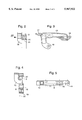
- FIG. 2 a section through the tension lever along line II--II of FIG. 1;
- FIG. 3 a view of the tension lever following the direction of the arrow III--III of FIG. 2;
- FIG. 4 a section through the guide rail and the tension lever mounted thereon, along line IV--IV of FIG. 1;
- FIG. 5 a top view of the guide rail
- FIG. 6 a further embodiment of the tensioning device, mounted in the cylinder head of the internal combustion engine with the tension lever mounted separately from the guide rail.
- a tensioning device of the invention shown in FIG. 1 is installed in a cylinder head 1 of an internal combustion engine.
- the installing space is closed in outward direction by a cylinder head cover 2.
- the function of the tensioning device is to produce a pre-tension in a chain 3 which is slung around a chain pulley 4 of a first camshaft 5 and a chain pulley 6 of a second camshaft 7.
- the chain pulley 4 is driven by the crankshaft via a further chain drive, not shown, so that this chain pulley 4 is the driving pulley for the chain 3 and the chain pulley 6 is the driven pulley.
- the tensioning device comprising a guide rail 8 situated in the vicinity of the tensioned portion 9 of the chain 3 is arranged between the chain pulleys 4 and 6.
- a slide lining 10 provided on the side of the guide rail 8 facing the tensioned portion 9 of the chain 3 prevents a transverse vibration of the chain 3 during operation.
- the guide rail 8 is configured as a light-weight body and detachably fixed on the cylinder head 1 by two screws 11.
- a tension element 13 is lodged in a cylindrical tensioner housing 12 formed on the guide rail 8. By virtue of its compression spring 14, the tension element 13 indirectly exerts a force on a tension lever 15 which is pivoted on an axis of pivot 16 on the guide rail 8.
- a first sliding block 17 and a second sliding block 18, both made of a plastics material, are affixed one behind the other in chain running direction on the tension lever 15.
- the sliding blocks 17 and 18 are arranged so as to act on the chain 3 on the slack portion 19 thereof, the sliding block 17 acting on the outer side of the chain 3 and the sliding block 18 on the inner side of the chain 3 seen in relation to the chain pulleys 4 and 6.
- the application of tensioning force by the tension element 13 on the tension lever 15 is effected in that a piston of the tension element 13 which can extend out of the tensioner housing 12 presses against the bottom surface of the second sliding block 18 facing away from the chain 3 so that the upper surface of the sliding block 18 facing the slack portion 19 of the chain 3 presses the chain 3 towards the outside of the chain drive.
- the first sliding block 17 simultaneously presses the slack portion 19 of the chain 3 at another point towards the inside of the chain drive. Due to these opposed movements of the sliding blocks 17 and 18, a relatively large chain elongation can be compensated whereby the chain 3 acquires a slightly sinusoidal shape in its slack portion 19 while being only slightly displaced in other portions. The shape of the chain is therefore only slightly different from that of a non-elongated chain.
- the required tensioning displacement of this sliding block would be much larger. If the chain were tensioned only towards the outside, i.e. upwards, it would graze the cylinder head cover 2. If tensioning were effected only towards the inside, i.e. downwards, the chain 3 would be deflected to such an extent that it would not be possible to arrange any other components in this space.
- the invention permits the arrangement of a third camshaft 20 with its bearing in the space delimited on one side by the tensioner housing 12 and the sliding block 18 and on the other side by the tension lever 15 and the sliding block 17 without a detrimental effect on said third camshaft 20 or its bearing during tensioning of the chain and deflection thereof.
- This third camshaft 20 can be part of a further control gear, not shown.
- a stop surface 21 on the sliding block 18 on its side facing away from the chain 3 can be seen in FIG. 2. It is against this surface 21 that the piston of the tension element 13 producing the tensioning force bears. Because the sliding block is made of a plastics material, noise generation on this stop surface is kept at a low level.
- FIG. 4 shows the screwing plane 22 of the guide rail 8 for fixing it in the cylinder head 1.
- the embodiment of the tensioning device shown in FIG. 6 has basically the same configuration as the embodiment of FIGS. 1 to 5 with the difference that the tension lever 23 is not pivoted on the guide rail 24 but on a bearing cap 25 of a bearing of the third camshaft 20.
- the axis of pivot 26 of the tension lever 23 is situated on this bearing cap 25.
Landscapes
- Engineering & Computer Science (AREA)
- General Engineering & Computer Science (AREA)
- Mechanical Engineering (AREA)
- Devices For Conveying Motion By Means Of Endless Flexible Members (AREA)
Abstract
Description
Claims (18)
Applications Claiming Priority (3)
| Application Number | Priority Date | Filing Date | Title |
|---|---|---|---|
| DE19536643A DE19536643A1 (en) | 1995-09-30 | 1995-09-30 | Clamping device for a control drive |
| DE19536643 | 1995-09-30 | ||
| PCT/EP1996/003536 WO1997013081A1 (en) | 1995-09-30 | 1996-08-09 | Tensioning device for a control drive |
Publications (1)
| Publication Number | Publication Date |
|---|---|
| US5967922A true US5967922A (en) | 1999-10-19 |
Family
ID=7773793
Family Applications (1)
| Application Number | Title | Priority Date | Filing Date |
|---|---|---|---|
| US09/029,237 Expired - Fee Related US5967922A (en) | 1995-09-30 | 1996-08-09 | Tensioning device for a control gear |
Country Status (3)
| Country | Link |
|---|---|
| US (1) | US5967922A (en) |
| DE (2) | DE19536643A1 (en) |
| WO (1) | WO1997013081A1 (en) |
Cited By (31)
| Publication number | Priority date | Publication date | Assignee | Title |
|---|---|---|---|---|
| WO2001013008A1 (en) * | 1999-08-16 | 2001-02-22 | Victory In Jesus Ministries, Inc. | Torque transfer device |
| US6302816B1 (en) * | 2000-03-07 | 2001-10-16 | Borgwarner Inc. | Chain guide or tensioner arm with sheet metal bracket and alternating tabs |
| US6322469B1 (en) * | 2000-04-21 | 2001-11-27 | Borgwarner Inc. | Dual arm chain tensioner for contacting multiple chain strands |
| US6358169B1 (en) * | 2000-05-02 | 2002-03-19 | Borgwarner Inc. | Chain tensioner system having a pivoting tensioner arm |
| US6375587B1 (en) * | 1999-11-12 | 2002-04-23 | Borgwarner Inc. | Timing chain having multiple blade tensioners contacting the same section of chain |
| US6447414B1 (en) * | 1998-12-15 | 2002-09-10 | Borgwarner Inc. | Hydraulic tensioner having flexible blade arm |
| EP1241380A3 (en) * | 2001-03-12 | 2003-07-23 | Tsubakimoto Chain Co. | Pivot member for a transmission belt guide |
| US20050085322A1 (en) * | 2003-10-15 | 2005-04-21 | Borgwarner Inc. | Pivoting chain guide and tensioner assembly |
| US20060040775A1 (en) * | 2004-08-19 | 2006-02-23 | Tsubakimoto Chain Co. | Power transmission incorporating tensioner lever |
| US20060089222A1 (en) * | 2004-10-12 | 2006-04-27 | Borgwarner Morse Tec Japan K.K. | Chain guide |
| US20060247080A1 (en) * | 2003-10-15 | 2006-11-02 | Borgwarner Inc. | Chain tensioning device linking two strands of a chain drive |
| US20060270502A1 (en) * | 2005-05-27 | 2006-11-30 | Borgwarner Inc. | Tensioner for simultaneously tensioning multiple strands |
| US20060293134A1 (en) * | 2005-06-28 | 2006-12-28 | Borgwarner Inc. | Pivoting mechanical tensioner with compliant blade spring |
| US20060293136A1 (en) * | 2005-06-28 | 2006-12-28 | Borgwarner Inc. | Mechanical chain tensioner with compliant blade spring |
| US20070240658A1 (en) * | 2004-02-23 | 2007-10-18 | Carlo Baldovino | Toothed Belt |
| US20080214341A1 (en) * | 2005-07-16 | 2008-09-04 | Schaeffler Kg | Belt Drive |
| US20110201465A1 (en) * | 2008-09-29 | 2011-08-18 | Borgwarner Inc. | Tensioning device |
| US8979684B2 (en) | 2010-05-21 | 2015-03-17 | Borgwarner, Inc. | Mechanical tensioner with one way damping |
| US9080640B2 (en) | 2009-11-03 | 2015-07-14 | Borgwarner, Inc. | Multi-strand tensioning arrangement with moving arms |
| US9188202B2 (en) | 2010-05-21 | 2015-11-17 | Borgwarner, Inc. | Tensioning mechanism for a continuous belt or chain drive system |
| US20160097440A1 (en) * | 2014-10-02 | 2016-04-07 | Iwis Motorsysteme Gmbh & Co. Kg | Tensioning or guide rail with opening |
| US20170009849A1 (en) * | 2015-07-08 | 2017-01-12 | Iwis Motorsysteme Gmbh & Co. Kg | Modular guide rail or modular tensioning rail |
| US9611920B2 (en) | 2014-10-10 | 2017-04-04 | Ford Global Technologies, Llc | Chain tensioner force mechanism for internal combustion engine |
| US20170276216A1 (en) * | 2014-10-02 | 2017-09-28 | Iwis Motorsysteme Gmbh & Co. Kg | Chain drive having a plurality of sliding elements |
| US20180231106A1 (en) * | 2015-08-28 | 2018-08-16 | Iwis Motorsysteme Gmbh & Co. Kg | Chain drive with a combination rail |
| US10408095B2 (en) * | 2015-01-05 | 2019-09-10 | Edward Charles Mendler | Variable compression ratio engine camshaft drive |
| US20230045513A1 (en) * | 2020-01-14 | 2023-02-09 | Magna International Inc. | Chain drive oil separator |
| US11796040B2 (en) | 2021-01-22 | 2023-10-24 | Borgwarner Inc. | Method(s) to apply tension to increase drivetrain jump torque capacity |
| US12078245B2 (en) | 2022-05-31 | 2024-09-03 | Borgwarner Inc. | Face of tensioner guide or arm with pattern to influence chain system NVH performance |
| US12320425B2 (en) | 2021-01-22 | 2025-06-03 | Borgwarner Inc. | Tooth jump protection device |
| US12435774B2 (en) | 2021-01-22 | 2025-10-07 | Borgwarner, Inc. | Tooth jump protection device |
Families Citing this family (8)
| Publication number | Priority date | Publication date | Assignee | Title |
|---|---|---|---|---|
| DE19717409A1 (en) * | 1997-04-25 | 1998-10-29 | Schaeffler Waelzlager Ohg | Chain tensioner |
| DE10341966A1 (en) * | 2003-09-11 | 2005-04-21 | Bayerische Motoren Werke Ag | Chain guide device especially for timing chain in motor vehicles has two chain guide elements with connecting coupling structure to form integral component for position-correct installation |
| DE102004014486B4 (en) * | 2004-03-24 | 2010-12-02 | Joh. Winklhofer & Söhne GmbH und Co. KG | Clamping rail, pivotally mounted on a guide rail |
| DE102005019694A1 (en) | 2005-04-28 | 2006-11-02 | Schaeffler Kg | Tensioning device for traction mechanism drive has supporting element pre-mounted in or on tensioning shoe with force-locking and/or shape-locking connection, connected to piston and in contact with piston recess |
| FR2917465B1 (en) * | 2007-06-12 | 2009-08-21 | Peugeot Citroen Automobiles Sa | INTERNAL COMBUSTION ENGINE HAVING INTEGRATED CHAIN TENSION DEVICE WITH CYLINDER HEAD COVER |
| DE102008054515A1 (en) | 2008-12-11 | 2010-06-24 | Ford Global Technologies, LLC, Dearborn | Drive system for combustion engine of motor vehicle, has axis arranged in slide rail such that attachment region is pressed against drive unit with respect to movement of extension by movements of drive unit in oppositely oriented manner |
| CN104444120A (en) * | 2014-10-03 | 2015-03-25 | 安徽轩扬包装科技有限公司 | Conveying equipment for packaging machinery |
| EP3130821B1 (en) * | 2015-08-12 | 2019-01-02 | iwis motorsysteme GmbH & Co. KG | Timing chain system |
Citations (15)
| Publication number | Priority date | Publication date | Assignee | Title |
|---|---|---|---|---|
| US389835A (en) * | 1888-09-18 | Oeville cooley | ||
| US2129107A (en) * | 1936-03-28 | 1938-09-06 | Fairbanks Morse & Co | Power transmission mechanism |
| US2210276A (en) * | 1938-07-12 | 1940-08-06 | Morse Chain Co | Chain adjuster |
| US2791910A (en) * | 1955-02-16 | 1957-05-14 | Goodman Mfg Co | Take-up device for v-belt drives |
| GB1206705A (en) * | 1968-11-19 | 1970-09-30 | G D Mountfield Ltd | Improvements in rotary mowers or grass cutters |
| US3817114A (en) * | 1973-01-29 | 1974-06-18 | Case Co J I | Chain tightener for endless chain |
| US3869138A (en) * | 1973-04-04 | 1975-03-04 | Ford Motor Co | Steering device having a chain operated steering gear actuator |
| DE2431425A1 (en) * | 1974-06-29 | 1976-01-15 | Bosch Gmbh Robert | TENSION RAIL FOR CHAIN DRIVES |
| US3964331A (en) * | 1974-06-26 | 1976-06-22 | Renold Limited | Damper apparatus |
| US4850934A (en) * | 1988-06-02 | 1989-07-25 | Moxee Innovations Corporation | Stabilized tensioning device for flexible drive element |
| EP0343136A1 (en) * | 1988-05-19 | 1989-11-23 | Saab Automobile Aktiebolag | Tensioning arrangement for a power-transmitting element incorporated in a transmission |
| DE4028756C1 (en) * | 1990-09-11 | 1992-03-26 | Heidelberger Druckmaschinen Ag, 6900 Heidelberg, De | |
| GB2254670A (en) * | 1991-04-11 | 1992-10-14 | Tsubakimoto Chain Co | Floating preventive structure for shoe of tensioner lever |
| US5222917A (en) * | 1991-04-15 | 1993-06-29 | Tsubakimoto Chain Co. | Tensioner lever having an i-shaped section |
| US5606941A (en) * | 1994-08-17 | 1997-03-04 | Dr.Ing. H.C.F. Porsche Ag | Variable timing camshaft drive system |
-
1995
- 1995-09-30 DE DE19536643A patent/DE19536643A1/en not_active Withdrawn
-
1996
- 1996-08-09 DE DE19680850T patent/DE19680850D2/en not_active Expired - Fee Related
- 1996-08-09 WO PCT/EP1996/003536 patent/WO1997013081A1/en not_active Ceased
- 1996-08-09 US US09/029,237 patent/US5967922A/en not_active Expired - Fee Related
Patent Citations (15)
| Publication number | Priority date | Publication date | Assignee | Title |
|---|---|---|---|---|
| US389835A (en) * | 1888-09-18 | Oeville cooley | ||
| US2129107A (en) * | 1936-03-28 | 1938-09-06 | Fairbanks Morse & Co | Power transmission mechanism |
| US2210276A (en) * | 1938-07-12 | 1940-08-06 | Morse Chain Co | Chain adjuster |
| US2791910A (en) * | 1955-02-16 | 1957-05-14 | Goodman Mfg Co | Take-up device for v-belt drives |
| GB1206705A (en) * | 1968-11-19 | 1970-09-30 | G D Mountfield Ltd | Improvements in rotary mowers or grass cutters |
| US3817114A (en) * | 1973-01-29 | 1974-06-18 | Case Co J I | Chain tightener for endless chain |
| US3869138A (en) * | 1973-04-04 | 1975-03-04 | Ford Motor Co | Steering device having a chain operated steering gear actuator |
| US3964331A (en) * | 1974-06-26 | 1976-06-22 | Renold Limited | Damper apparatus |
| DE2431425A1 (en) * | 1974-06-29 | 1976-01-15 | Bosch Gmbh Robert | TENSION RAIL FOR CHAIN DRIVES |
| EP0343136A1 (en) * | 1988-05-19 | 1989-11-23 | Saab Automobile Aktiebolag | Tensioning arrangement for a power-transmitting element incorporated in a transmission |
| US4850934A (en) * | 1988-06-02 | 1989-07-25 | Moxee Innovations Corporation | Stabilized tensioning device for flexible drive element |
| DE4028756C1 (en) * | 1990-09-11 | 1992-03-26 | Heidelberger Druckmaschinen Ag, 6900 Heidelberg, De | |
| GB2254670A (en) * | 1991-04-11 | 1992-10-14 | Tsubakimoto Chain Co | Floating preventive structure for shoe of tensioner lever |
| US5222917A (en) * | 1991-04-15 | 1993-06-29 | Tsubakimoto Chain Co. | Tensioner lever having an i-shaped section |
| US5606941A (en) * | 1994-08-17 | 1997-03-04 | Dr.Ing. H.C.F. Porsche Ag | Variable timing camshaft drive system |
Non-Patent Citations (2)
| Title |
|---|
| Patent Abstract of Japanese Patent 59 20850(A). * |
| Patent Abstract of Japanese Patent 59-20850(A). |
Cited By (50)
| Publication number | Priority date | Publication date | Assignee | Title |
|---|---|---|---|---|
| US6447414B1 (en) * | 1998-12-15 | 2002-09-10 | Borgwarner Inc. | Hydraulic tensioner having flexible blade arm |
| US6193624B1 (en) * | 1999-08-16 | 2001-02-27 | Victory In Jesus Ministries, Inc. | Torque transfer device |
| WO2001013008A1 (en) * | 1999-08-16 | 2001-02-22 | Victory In Jesus Ministries, Inc. | Torque transfer device |
| US6375587B1 (en) * | 1999-11-12 | 2002-04-23 | Borgwarner Inc. | Timing chain having multiple blade tensioners contacting the same section of chain |
| US6302816B1 (en) * | 2000-03-07 | 2001-10-16 | Borgwarner Inc. | Chain guide or tensioner arm with sheet metal bracket and alternating tabs |
| US6322469B1 (en) * | 2000-04-21 | 2001-11-27 | Borgwarner Inc. | Dual arm chain tensioner for contacting multiple chain strands |
| US6358169B1 (en) * | 2000-05-02 | 2002-03-19 | Borgwarner Inc. | Chain tensioner system having a pivoting tensioner arm |
| EP1241380A3 (en) * | 2001-03-12 | 2003-07-23 | Tsubakimoto Chain Co. | Pivot member for a transmission belt guide |
| US20060247080A1 (en) * | 2003-10-15 | 2006-11-02 | Borgwarner Inc. | Chain tensioning device linking two strands of a chain drive |
| US20050085322A1 (en) * | 2003-10-15 | 2005-04-21 | Borgwarner Inc. | Pivoting chain guide and tensioner assembly |
| US7537533B2 (en) | 2003-10-15 | 2009-05-26 | Borgwarner Inc. | Chain tensioning device linking two strands of a chain drive |
| US7097579B2 (en) | 2003-10-15 | 2006-08-29 | Borgwarner Inc. | Pivoting chain guide and tensioner assembly |
| US20100240481A1 (en) * | 2004-02-23 | 2010-09-23 | Dayco Europe S.R.I. | Toothed belt |
| US7749118B2 (en) * | 2004-02-23 | 2010-07-06 | Dayco Europe S.R.L. | Toothed Belt |
| US8568260B2 (en) | 2004-02-23 | 2013-10-29 | Dayco Europe S.R.L. | Toothed belt for use with oil and relative timing control system |
| US8388477B2 (en) | 2004-02-23 | 2013-03-05 | Dayco Europe S.R.L. | Toothed belt |
| US20070240658A1 (en) * | 2004-02-23 | 2007-10-18 | Carlo Baldovino | Toothed Belt |
| US20070281814A1 (en) * | 2004-02-23 | 2007-12-06 | Carlo Baldovino | Toothed Belt for Use with Oil and Relative Timing Control System |
| US7404777B2 (en) * | 2004-08-19 | 2008-07-29 | Tsubakimoto Chain Co. | Power transmission incorporating tensioner lever |
| US20060040775A1 (en) * | 2004-08-19 | 2006-02-23 | Tsubakimoto Chain Co. | Power transmission incorporating tensioner lever |
| US20060089222A1 (en) * | 2004-10-12 | 2006-04-27 | Borgwarner Morse Tec Japan K.K. | Chain guide |
| US20060270502A1 (en) * | 2005-05-27 | 2006-11-30 | Borgwarner Inc. | Tensioner for simultaneously tensioning multiple strands |
| US7641577B2 (en) | 2005-06-28 | 2010-01-05 | Borgwarner Inc. | Mechanical chain tensioner with compliant blade spring |
| US7479077B2 (en) | 2005-06-28 | 2009-01-20 | Borgwarner Inc. | Pivoting mechanical tensioner with compliant blade spring |
| US20060293136A1 (en) * | 2005-06-28 | 2006-12-28 | Borgwarner Inc. | Mechanical chain tensioner with compliant blade spring |
| US20060293134A1 (en) * | 2005-06-28 | 2006-12-28 | Borgwarner Inc. | Pivoting mechanical tensioner with compliant blade spring |
| US20080214341A1 (en) * | 2005-07-16 | 2008-09-04 | Schaeffler Kg | Belt Drive |
| US20110053719A1 (en) * | 2005-07-16 | 2011-03-03 | Schaeffler Technologies Gmbh & Co. Kg | Belt drive |
| US8267822B2 (en) * | 2005-07-16 | 2012-09-18 | Schaeffler Technologies AG & Co. KG | Wrap-around drive |
| US20110201465A1 (en) * | 2008-09-29 | 2011-08-18 | Borgwarner Inc. | Tensioning device |
| US8608601B2 (en) | 2008-09-29 | 2013-12-17 | Borgwarner Inc. | Tensioning device |
| US9080640B2 (en) | 2009-11-03 | 2015-07-14 | Borgwarner, Inc. | Multi-strand tensioning arrangement with moving arms |
| US8979684B2 (en) | 2010-05-21 | 2015-03-17 | Borgwarner, Inc. | Mechanical tensioner with one way damping |
| US9188202B2 (en) | 2010-05-21 | 2015-11-17 | Borgwarner, Inc. | Tensioning mechanism for a continuous belt or chain drive system |
| US20160097440A1 (en) * | 2014-10-02 | 2016-04-07 | Iwis Motorsysteme Gmbh & Co. Kg | Tensioning or guide rail with opening |
| US10495193B2 (en) * | 2014-10-02 | 2019-12-03 | Iwis Motorsysteme Gmbh & Co. Kg | Chain drive having a plurality of sliding elements |
| US9689475B2 (en) * | 2014-10-02 | 2017-06-27 | Iwis Motorsysteme Gmbh & Co. Kg | Tensioning or guide rail with opening |
| US20170276216A1 (en) * | 2014-10-02 | 2017-09-28 | Iwis Motorsysteme Gmbh & Co. Kg | Chain drive having a plurality of sliding elements |
| US9611920B2 (en) | 2014-10-10 | 2017-04-04 | Ford Global Technologies, Llc | Chain tensioner force mechanism for internal combustion engine |
| RU2692878C2 (en) * | 2014-10-10 | 2019-06-28 | Форд Глобал Текнолоджиз, Ллк | Circuit tensioner for internal combustion engine (embodiments) and internal combustion engine |
| US10408095B2 (en) * | 2015-01-05 | 2019-09-10 | Edward Charles Mendler | Variable compression ratio engine camshaft drive |
| US10378619B2 (en) * | 2015-07-08 | 2019-08-13 | Iwis Motorsysteme Gmbh & Co. Kg | Modular guide rail or modular tensioning rail |
| US20170009849A1 (en) * | 2015-07-08 | 2017-01-12 | Iwis Motorsysteme Gmbh & Co. Kg | Modular guide rail or modular tensioning rail |
| US20180231106A1 (en) * | 2015-08-28 | 2018-08-16 | Iwis Motorsysteme Gmbh & Co. Kg | Chain drive with a combination rail |
| US10876603B2 (en) * | 2015-08-28 | 2020-12-29 | Iwis Motorsysteme Gmbh & Co. Kg | Chain drive with a combination rail |
| US20230045513A1 (en) * | 2020-01-14 | 2023-02-09 | Magna International Inc. | Chain drive oil separator |
| US11796040B2 (en) | 2021-01-22 | 2023-10-24 | Borgwarner Inc. | Method(s) to apply tension to increase drivetrain jump torque capacity |
| US12320425B2 (en) | 2021-01-22 | 2025-06-03 | Borgwarner Inc. | Tooth jump protection device |
| US12435774B2 (en) | 2021-01-22 | 2025-10-07 | Borgwarner, Inc. | Tooth jump protection device |
| US12078245B2 (en) | 2022-05-31 | 2024-09-03 | Borgwarner Inc. | Face of tensioner guide or arm with pattern to influence chain system NVH performance |
Also Published As
| Publication number | Publication date |
|---|---|
| WO1997013081A1 (en) | 1997-04-10 |
| DE19680850D2 (en) | 1998-10-01 |
| DE19536643A1 (en) | 1997-04-03 |
Similar Documents
| Publication | Publication Date | Title |
|---|---|---|
| US5967922A (en) | Tensioning device for a control gear | |
| CA2360521C (en) | Tensioner device | |
| US8267822B2 (en) | Wrap-around drive | |
| US5597367A (en) | Apparatus for tensioning of a cam shaft drive | |
| JP2000161073A (en) | Chain drive for internal combustion engine | |
| GB2280724A (en) | Autotensioner for belt | |
| JPS63140808A (en) | Adjustment device that adjusts the valve control time | |
| KR920008916B1 (en) | Camshaft bearing structure of DOHC engine | |
| US6561156B2 (en) | Cylinder head apparatus | |
| JPS6154979B2 (en) | ||
| GB2252389A (en) | Autotensioner | |
| US5730673A (en) | Hydraulic tensioning arrangement for tensioning flexible drive means for a camshaft | |
| US20070173362A1 (en) | Chain or synchronous belt drive and tensioning or guiding element for integrating into a chain or synchronous belt drive | |
| US7056246B2 (en) | Compliant chain guide with multiple joints | |
| US20070161444A1 (en) | Traction mechanism drive, in particular for an internal combustion engine | |
| JP2010014044A (en) | Timing system | |
| JP4543329B2 (en) | Engine front structure | |
| JP4635943B2 (en) | Timing chain tooth skip prevention structure | |
| US4758206A (en) | Cam shaft drive structure for OHC V-type engine | |
| JP2571983B2 (en) | Auto tensioner device | |
| JP2004028346A (en) | Tensioner device | |
| JP2004028346A5 (en) | ||
| JPH06288446A (en) | Engine chain tensioner device | |
| JPH0968053A (en) | Sensor mounting structure for internal combustion engine | |
| KR0135534Y1 (en) | Noise attenuator on the camshaft timing chain of the internal combustion engine |
Legal Events
| Date | Code | Title | Description |
|---|---|---|---|
| AS | Assignment |
Owner name: INA WALZLAGER SCHAEFFLER OHG, GERMANY Free format text: ASSIGNMENT OF ASSIGNORS INTEREST;ASSIGNORS:ULLEIN, THOMAS;SCHUSEIL, BOLKO;REEL/FRAME:009112/0556 Effective date: 19980122 |
|
| FEPP | Fee payment procedure |
Free format text: PAYOR NUMBER ASSIGNED (ORIGINAL EVENT CODE: ASPN); ENTITY STATUS OF PATENT OWNER: LARGE ENTITY |
|
| REMI | Maintenance fee reminder mailed | ||
| AS | Assignment |
Owner name: INA-SCHAEFFLER KG, GERMANY Free format text: CHANGE OF NAME;ASSIGNOR:INA WALZLAGER SCHAEFFLER OHG;REEL/FRAME:014210/0737 Effective date: 20021014 |
|
| LAPS | Lapse for failure to pay maintenance fees | ||
| STCH | Information on status: patent discontinuation |
Free format text: PATENT EXPIRED DUE TO NONPAYMENT OF MAINTENANCE FEES UNDER 37 CFR 1.362 |
|
| FP | Lapsed due to failure to pay maintenance fee |
Effective date: 20031019 |