US5967742A - Method and apparatus for preventing surge while taking a turbocompressor off-line from a parallel configuration - Google Patents
Method and apparatus for preventing surge while taking a turbocompressor off-line from a parallel configuration Download PDFInfo
- Publication number
- US5967742A US5967742A US08/996,891 US99689197A US5967742A US 5967742 A US5967742 A US 5967742A US 99689197 A US99689197 A US 99689197A US 5967742 A US5967742 A US 5967742A
- Authority
- US
- United States
- Prior art keywords
- line
- turbocompressor
- control line
- surge
- taking
- Prior art date
- Legal status (The legal status is an assumption and is not a legal conclusion. Google has not performed a legal analysis and makes no representation as to the accuracy of the status listed.)
- Expired - Lifetime
Links
- 238000000034 method Methods 0.000 title claims abstract description 26
- 230000009467 reduction Effects 0.000 claims abstract description 14
- 230000003247 decreasing effect Effects 0.000 claims abstract description 13
- 230000009471 action Effects 0.000 abstract description 3
- 230000000694 effects Effects 0.000 abstract description 3
- 230000002265 prevention Effects 0.000 abstract description 2
- 230000000977 initiatory effect Effects 0.000 abstract 1
- 230000007423 decrease Effects 0.000 description 4
- 238000010586 diagram Methods 0.000 description 3
- 230000008859 change Effects 0.000 description 2
- 239000000446 fuel Substances 0.000 description 1
- 238000012986 modification Methods 0.000 description 1
- 230000004048 modification Effects 0.000 description 1
- 238000011017 operating method Methods 0.000 description 1
- 230000008569 process Effects 0.000 description 1
- 238000004064 recycling Methods 0.000 description 1
- 230000004044 response Effects 0.000 description 1
Images


Classifications
-
- F—MECHANICAL ENGINEERING; LIGHTING; HEATING; WEAPONS; BLASTING
- F04—POSITIVE - DISPLACEMENT MACHINES FOR LIQUIDS; PUMPS FOR LIQUIDS OR ELASTIC FLUIDS
- F04D—NON-POSITIVE-DISPLACEMENT PUMPS
- F04D27/00—Control, e.g. regulation, of pumps, pumping installations or pumping systems specially adapted for elastic fluids
- F04D27/02—Surge control
- F04D27/0207—Surge control by bleeding, bypassing or recycling fluids
-
- F—MECHANICAL ENGINEERING; LIGHTING; HEATING; WEAPONS; BLASTING
- F04—POSITIVE - DISPLACEMENT MACHINES FOR LIQUIDS; PUMPS FOR LIQUIDS OR ELASTIC FLUIDS
- F04D—NON-POSITIVE-DISPLACEMENT PUMPS
- F04D27/00—Control, e.g. regulation, of pumps, pumping installations or pumping systems specially adapted for elastic fluids
- F04D27/02—Surge control
- F04D27/0284—Conjoint control of two or more different functions
Definitions
- This invention relates generally to a method and apparatus for preventing surge while quickly taking a turbocompressor off-line from a parallel configuration of turbocompressors within a gas pipeline compressor station. More specifically, the invention relates to a method that achieves surge prevention by altering (at a preset rate) the surge control line's location; and, if needed, by altering the deceleration rate of the turbocompressor while taking it off-line.
- the first method involves fully opening an antisurge (recycle) valve, along with sequentially closing a block valve at the turbocompressor's discharge, and then reducing the turbocompressor's rotational speed.
- the second method involves decreasing the turbocompressor's rotational speed while its antisurge controller is operating automatically.
- the recycle valve is then opened, based upon the antisurge controller's requirement to keep the turbocompressor's operating point on the surge control line.
- a disadvantage of the first method is the onset of increased mechanical action (in particular, vibratory) upon recycle piping. This is due to the flow rate of gas (passing through a fully opened recycle valve) being significantly larger than the flow rate needed to prevent surge.
- a disadvantage of the second method is the low decreasing-rate of turbocompressor rotational speed required for surge prevention--that is, the antisurge controller is set to open the recycle valve when the operating point is close to the surge limit line, and the controller's speed-of-action is limited by conditions of control-system stability. This reduced deceleration rate of the turbocompressor being brought off-line diminishes the effectiveness of a station's overall control.
- the purpose of this invention is twofold: (1) shorten the time required to take a compressor off-line, and (2) reduce the risk of high mechanical loads (particularly vibration) on recycle piping during compressor deceleration.
- the emphasis of this technique is directed to turbocompressors used in gas pipeline compressor stations; although the method has applications with other types of turbocompressor groups.
- This method proposes moving the surge control line of an antisurge controller to a predetermined new location farther from the surge limit line while the compressor is being decelerated.
- the surge control line is returned to its initial location at a preset rate. If, however, a compressor's operating point reaches (intercepts) the control line before the control line reaches its new location, the compressor's deceleration rate is reduced as a function of (1) that distance from the initial location (before deceleration) to the control line's current location where the operating point intercepts it, and (2) that distance from the initial location (before deceleration) of the control line to its predetermined new location.
- Completion of an off-line operation can be indicated by (a) a difference between the discharge pressure of the compressor brought off-line and the common discharge pressure of the remaining compressors, (b) a position of the recycle valve, (c) compressor rotational speed, or (d) the expiration of a time period.
- a signal may be generated to indicate to the antisurge controller that its surge control line may be returned to its initial location.
- the reduction of compressor rotational speed will cease upon reaching a predefined value.
- FIG. 1 shows a parallel configuration comprising three turbocompressors.
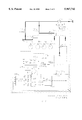
- FIG. 2 shows a functional diagram of a turbocompressor control system.
- FIG. 3 shows a compressor map
- FIG. 4 shows the effect of the reduction of the compressor's rotational speed on the surge control line and operating point with respect to time, when the surge control line reaches its predetermined new location before being intercepted by the operating point.
- FIG. 5 shows the effect of the reduction of the compressor's rotational speed of the surge control line and operating point with respect to time, when the operating point intercepts the surge control line before the control line reaches its predetermined new location.
- each compressor is equipped with an antisurge valve and an antisurge controller that modulates that valve.
- the drivers (gas turbines) for the compressors are each equipped with a fuel control valve and a rotational speed controller.
- FIG. 1 A representation of a parallel turbocompressor arrangement is shown in FIG. 1 and consists of three compressors 101, 102, 103 with accompanying drivers (gas turbines) 111, 112, 113.
- Each compressor-driver unit is equipped with a check valve 121, 122, 123 and a recycle valve 131, 132, 133; moreover, these three units commonly share a suction header 140 and discharge header 142.
- FIG. 2 shows a functional diagram of a compressor-driver unit comprising a compressor 101 and a driver 111 (as depicted in FIG. 1).
- This unit is equipped with a suction-pressure transmitter (PT-p s ) 202, a differential-pressure transmitter (FT- ⁇ p o ) 204 for a flow measuring device 206, a discharge-pressure transmitter PT-p d ) 208, and a rotational speed transmitter (ST-N) 210.
- PT-p s suction-pressure transmitter
- FT- ⁇ p o differential-pressure transmitter
- ST-N rotational speed transmitter
- Transmitters PT-p s , FT- ⁇ p o , and PT-p d are connected to a computation block 212 that calculates an antisurge control variable which can take on several forms, for instance ##EQU1## and then inputs this variable to an antisurge controller 214 which is also inputted by a summing block 216 that receives signals from a predefined set point (SP) 218 and from the first of three integrators 220, 222, 224.
- SP set point
- the speed transmitter (ST-N) 210 sends a signal to a speed controller 226 and, indirectly, to a logic controller 228 by way of a frequency-analog signal converter 230 and a speed-comparator block 232.
- a pressure-differential switch ( ⁇ p) 234 connected in parallel with a check valve 121, transmits directly to the logic controller 228 which is inputted by two additional signals: the output of a recycle-valve status block 236, and that from a function block 238.
- the logic controller 228, outputs to three integrators 220, 222, 224 which, respectively, output to the summing block 216, speed controller 226, and function block 238.
- the antisurge controller 214 and the speed controller 226 coordinate their specific tasks to shorten the time required to take the turbocompressor off-line, as well as to lessen the mechanical loads on the recycle piping by the following actions:
- the antisurge controller 214 After processing the inputs from both the computation block 212 and the summing block 216, the antisurge controller 214 transmits to the recycle valve 131 and, concurrently, to the recycle-valve status block 236.
- the speed controller 226 After processing inputs from both the rotational-speed transmitter 210 and the second integrator 222, the speed controller 226 transmits to a final control element 240.
- the logic controller 228 outputs are transmitted to three integrators 220, 222, 224 whose output signals are changed at preset rates.
- the surge control line 302 begins moving (at a preset rate) to the right of its initial location (away from the surge limit line 304) and toward its predetermined new location 306.
- the second integrator's 222 output decreases to a preset value, and the rotational speed set point also decreases.
- S ⁇ 1 is the operating point's location relative to the surge control line and b is a safety margin--by increasing the value of b, the distance between the surge control line and the surge limit line is increased.
- This procedure can be further described by two scenarios in which a compressor is brought off-line without surging or recycling more than necessary.
- Scenario 1 (see FIG. 4) The significance of Scenario 1 is that during reduction of the compressor's rotational speed, the surge control line will reach its predetermined new location before being intercepted by the operating point.
- the function block's 238 output will be set to a level equal to the second integrator's 222 input because the outputs of the second and third integrators 222, 224 change simultaneously.
- the antisurge controller 214 will instruct the recycle valve 131 to start opening.
- the antisurge controller actuates the recycle-valve status block's 236 preset signal (inputted directly to the logic controller 228) that triggers a logic operation connecting the second integrator's 222 input with the function block's 238 output signal whose level now equals the level of the second integrator's 222 input signal source to which it was connected before being connected with the flnction block's 238 output.
- the ongoing reduction of the compressor's rotational speed (by way of the speed controller 226) will continue at a predetermined rate.
- the pressure differential ( ⁇ p) across the check valve reaches a set point of the pressure-differential switch 234.
- This switch's signal (which corresponds to the check valve's closed position after an off-line operation) is transmitted to and processed by the logic controller 228 which, in turn, inputs to both the first and third integrators 220, 224 in order to return their output signals to prior values.
- Scenario 2 (see FIG. 5) The significance of Scenario 2 is that during reduction of the compressor's rotational speed, its operating point intercepts the surge control line before the control line reaches its predetermined new location.
- the recycle-valve status block 236 signal When the operating point 308 intercepts the control line, the recycle-valve status block 236 signal will input to the logic controller 228. This causes the function block 238 to initiate a logic operation linking the input of the second integrator 222 with the output of the flnction block 238, which is smaller than the input of the second integrator 222 before being linked to the function block 238. The resulting reduction of the second integrator's 222 output and the subsequent reduction of compressor speed will continue at a lower rate than before the operating point intercepted the surge control line.
- This lower rate is calculated as a function of the distance relationship (ratio) between (1) the surge control line's initial location 302 and its point-of-interception with the turbocompressor's operating point, and (2) the surge control line's initial location and its predetermined new location 306.
- ratio the distance relationship between (1) the surge control line's initial location 302 and its point-of-interception with the turbocompressor's operating point, and (2) the surge control line's initial location and its predetermined new location 306.
- the correlation between the output of the third integrator 224 and the deceleration rate (at the time the operating point intercepts the control line) is provided by the function block 238.
- the output signal of the third integrator ceases to change the deceleration rate, but the first integrator's 220 output continues to decrease, resulting in faster opening of the recycle valve 131.
- the rate of deceleration will increase to its initial value with (1) the appearance of the pressure-differential switch 234 signal, (2) the disconnection of the second integrator 222 from the output of the function block 238, and (3) linking the second integrator 222 with the signal source to which the second integrator's 222 input was connected before being connected with the function block's 238 output.
- Scenario 2 will be completed similarly to Scenario 1.
Landscapes
- Engineering & Computer Science (AREA)
- Mechanical Engineering (AREA)
- General Engineering & Computer Science (AREA)
- Life Sciences & Earth Sciences (AREA)
- Sustainable Development (AREA)
- Control Of Positive-Displacement Air Blowers (AREA)
Abstract
Description
Claims (16)
Priority Applications (2)
| Application Number | Priority Date | Filing Date | Title |
|---|---|---|---|
| US08/996,891 US5967742A (en) | 1997-12-23 | 1997-12-23 | Method and apparatus for preventing surge while taking a turbocompressor off-line from a parallel configuration |
| RU98123612/06A RU2194884C2 (en) | 1997-12-23 | 1998-12-22 | Method of and device for preventing stalling-and-surging of turbocompressor at changing over from parallel connection into off-line mode of operation |
Applications Claiming Priority (1)
| Application Number | Priority Date | Filing Date | Title |
|---|---|---|---|
| US08/996,891 US5967742A (en) | 1997-12-23 | 1997-12-23 | Method and apparatus for preventing surge while taking a turbocompressor off-line from a parallel configuration |
Publications (1)
| Publication Number | Publication Date |
|---|---|
| US5967742A true US5967742A (en) | 1999-10-19 |
Family
ID=25543402
Family Applications (1)
| Application Number | Title | Priority Date | Filing Date |
|---|---|---|---|
| US08/996,891 Expired - Lifetime US5967742A (en) | 1997-12-23 | 1997-12-23 | Method and apparatus for preventing surge while taking a turbocompressor off-line from a parallel configuration |
Country Status (2)
| Country | Link |
|---|---|
| US (1) | US5967742A (en) |
| RU (1) | RU2194884C2 (en) |
Cited By (11)
| Publication number | Priority date | Publication date | Assignee | Title |
|---|---|---|---|---|
| US6317655B1 (en) * | 1999-02-12 | 2001-11-13 | Compressor Controls Corporation | Method and apparatus for estimating a surge limit line for configuring an antisurge controller |
| US6494672B1 (en) * | 1999-06-07 | 2002-12-17 | Compressor Controls Corporation | Method and apparatus for antisurge control of turbocompressors having complex and changing surge limit lines |
| US20060185363A1 (en) * | 2005-02-21 | 2006-08-24 | Gustafson Richard J | Boost wastegate device for EGR assist |
| US20070150645A1 (en) * | 2005-12-28 | 2007-06-28 | Intel Corporation | Method, system and apparatus for power loss recovery to enable fast erase time |
| US20080056910A1 (en) * | 2006-09-05 | 2008-03-06 | Conocophillips Company | Anti-bogdown control system for turbine/compressor systems |
| WO2008138075A1 (en) * | 2007-05-15 | 2008-11-20 | Atlas Copco Airpower, Naamloze Vennootschap | Method for controlling a turbocoinpressor |
| GB2452128A (en) * | 2007-08-21 | 2009-02-25 | Compair Uk Ltd | Compressor Control |
| CN102606464A (en) * | 2011-12-15 | 2012-07-25 | 西安兴仪启动发电试运有限公司 | Real-time monitoring and preventing method for surge and stall of axial flow fan |
| EP2124004A3 (en) * | 2008-03-13 | 2013-01-30 | Compressor Controls Corporation | Compressor-expander set critical speed avoidance |
| US20130170952A1 (en) * | 2010-07-14 | 2013-07-04 | Statoil Asa | Method and apparatus for composition based compressor control and performance monitoring |
| US9879688B2 (en) | 2008-03-13 | 2018-01-30 | Compressor Controls Corporation | Enhanced turbocompressor startup |
Families Citing this family (2)
| Publication number | Priority date | Publication date | Assignee | Title |
|---|---|---|---|---|
| DE102010040503B4 (en) * | 2010-09-09 | 2012-05-10 | Siemens Aktiengesellschaft | Method for controlling a compressor |
| RU2617523C1 (en) * | 2016-04-12 | 2017-04-25 | Федеральное государственное бюджетное образовательное учреждение высшего профессионального образования "Уфимский государственный нефтяной технический университет" | Method of controlling the work of the compressor station when producing natural gas from the pipeline gas pipeline discharged for repair |
Citations (4)
| Publication number | Priority date | Publication date | Assignee | Title |
|---|---|---|---|---|
| US4046490A (en) * | 1975-12-01 | 1977-09-06 | Compressor Controls Corporation | Method and apparatus for antisurge protection of a dynamic compressor |
| US4486142A (en) * | 1977-12-01 | 1984-12-04 | Naum Staroselsky | Method of automatic limitation for a controlled variable in a multivariable system |
| US4861233A (en) * | 1983-10-07 | 1989-08-29 | The Babcock & Wilcox Company | Compressor surge control system |
| US5798941A (en) * | 1996-01-02 | 1998-08-25 | Woodward Governor Company | Surge prevention control system for dynamic compressors |
Family Cites Families (3)
| Publication number | Priority date | Publication date | Assignee | Title |
|---|---|---|---|---|
| US3945759A (en) * | 1974-10-29 | 1976-03-23 | General Electric Company | Bleed air manifold |
| US4595340A (en) * | 1984-07-30 | 1986-06-17 | General Electric Company | Gas turbine bladed disk assembly |
| RU2098669C1 (en) * | 1995-08-21 | 1997-12-10 | Открытое акционерное общество "Кировский завод" | Method of stabilization of gas dynamic stability margin for turbocomplex |
-
1997
- 1997-12-23 US US08/996,891 patent/US5967742A/en not_active Expired - Lifetime
-
1998
- 1998-12-22 RU RU98123612/06A patent/RU2194884C2/en active
Patent Citations (4)
| Publication number | Priority date | Publication date | Assignee | Title |
|---|---|---|---|---|
| US4046490A (en) * | 1975-12-01 | 1977-09-06 | Compressor Controls Corporation | Method and apparatus for antisurge protection of a dynamic compressor |
| US4486142A (en) * | 1977-12-01 | 1984-12-04 | Naum Staroselsky | Method of automatic limitation for a controlled variable in a multivariable system |
| US4861233A (en) * | 1983-10-07 | 1989-08-29 | The Babcock & Wilcox Company | Compressor surge control system |
| US5798941A (en) * | 1996-01-02 | 1998-08-25 | Woodward Governor Company | Surge prevention control system for dynamic compressors |
Cited By (31)
| Publication number | Priority date | Publication date | Assignee | Title |
|---|---|---|---|---|
| US6317655B1 (en) * | 1999-02-12 | 2001-11-13 | Compressor Controls Corporation | Method and apparatus for estimating a surge limit line for configuring an antisurge controller |
| US6494672B1 (en) * | 1999-06-07 | 2002-12-17 | Compressor Controls Corporation | Method and apparatus for antisurge control of turbocompressors having complex and changing surge limit lines |
| US20060185363A1 (en) * | 2005-02-21 | 2006-08-24 | Gustafson Richard J | Boost wastegate device for EGR assist |
| US7254948B2 (en) * | 2005-02-21 | 2007-08-14 | Cummins Inc. | Boost wastegate device for EGR assist |
| US20070150645A1 (en) * | 2005-12-28 | 2007-06-28 | Intel Corporation | Method, system and apparatus for power loss recovery to enable fast erase time |
| AU2007347705B2 (en) * | 2006-09-05 | 2013-01-10 | Conocophillips Company | Anti-bogdown control system for turbine/compressor systems |
| US20080056910A1 (en) * | 2006-09-05 | 2008-03-06 | Conocophillips Company | Anti-bogdown control system for turbine/compressor systems |
| US7712299B2 (en) * | 2006-09-05 | 2010-05-11 | Conocophillips Company | Anti-bogdown control system for turbine/compressor systems |
| WO2008138075A1 (en) * | 2007-05-15 | 2008-11-20 | Atlas Copco Airpower, Naamloze Vennootschap | Method for controlling a turbocoinpressor |
| BE1017600A3 (en) * | 2007-05-15 | 2009-01-13 | Atlas Copco Airpower Nv | METHOD FOR CONTROLLING A TURBO COMPRESSOR. |
| US9347454B2 (en) * | 2007-05-15 | 2016-05-24 | Atlas Copco Airpower, Naamloze Vennootschap | Method for controlling a turbocompressor |
| US20100074725A1 (en) * | 2007-05-15 | 2010-03-25 | Serbruyns Sven Bert | Method for controlling a turpocompressor |
| CN101600887B (en) * | 2007-05-15 | 2012-08-08 | 艾拉斯科普库空气动力股份有限公司 | Method of controlling a turbo compressor |
| RU2426011C2 (en) * | 2007-05-15 | 2011-08-10 | Атлас Копко Эрпауэр, Намлозе Веннотсхап | Method of controlling turbo compressor |
| US20120121440A1 (en) * | 2007-08-21 | 2012-05-17 | Geoffrey George Powell | Compressors control |
| CN102124230B (en) * | 2007-08-21 | 2015-04-08 | 嘉德纳丹佛德国有限公司 | Improvements in compressor control |
| CN102124230A (en) * | 2007-08-21 | 2011-07-13 | 嘉德纳丹佛德国有限公司 | Improvements in compressor control |
| GB2452128B (en) * | 2007-08-21 | 2009-09-30 | Compair Uk Ltd | Improvements in compressors control |
| GB2452128A (en) * | 2007-08-21 | 2009-02-25 | Compair Uk Ltd | Compressor Control |
| US9086070B2 (en) * | 2007-08-21 | 2015-07-21 | Gardner Denver Deutschland Gmbh | Compressors control |
| US20130129528A1 (en) * | 2008-03-13 | 2013-05-23 | Compressor Controls Corporation | Compressor-Expander Set Critical Speed Avoidance |
| US8540498B2 (en) * | 2008-03-13 | 2013-09-24 | Compressor Controls Corp. | Compressor-expander set critical speed avoidance |
| EP2124004A3 (en) * | 2008-03-13 | 2013-01-30 | Compressor Controls Corporation | Compressor-expander set critical speed avoidance |
| US9879688B2 (en) | 2008-03-13 | 2018-01-30 | Compressor Controls Corporation | Enhanced turbocompressor startup |
| US20180149163A1 (en) * | 2008-03-13 | 2018-05-31 | Compressor Controls Corporation | Enhanced turbocompressor starup |
| US10935036B2 (en) * | 2008-03-13 | 2021-03-02 | Compressor Controls Corporation | Enhanced turbocompressor startup |
| US20130170952A1 (en) * | 2010-07-14 | 2013-07-04 | Statoil Asa | Method and apparatus for composition based compressor control and performance monitoring |
| US9416790B2 (en) * | 2010-07-14 | 2016-08-16 | Statoil Asa | Method and apparatus for composition based compressor control and performance monitoring |
| US20170002822A1 (en) * | 2010-07-14 | 2017-01-05 | Statoil Asa | Method and apparatus for composition based compressor control and performance monitoring |
| CN102606464B (en) * | 2011-12-15 | 2014-12-10 | 西安兴仪启动发电试运有限公司 | Real-time monitoring and preventing method for surge and stall of axial flow fan |
| CN102606464A (en) * | 2011-12-15 | 2012-07-25 | 西安兴仪启动发电试运有限公司 | Real-time monitoring and preventing method for surge and stall of axial flow fan |
Also Published As
| Publication number | Publication date |
|---|---|
| RU2194884C2 (en) | 2002-12-20 |
Similar Documents
| Publication | Publication Date | Title |
|---|---|---|
| US5967742A (en) | Method and apparatus for preventing surge while taking a turbocompressor off-line from a parallel configuration | |
| US6551068B2 (en) | Process for protecting a turbocompressor from operating in the unstable working range | |
| JP2754079B2 (en) | Control method and control device for compressor system | |
| US4526513A (en) | Method and apparatus for control of pipeline compressors | |
| CA2184130A1 (en) | Method and apparatus for load balancing among multiple compressors | |
| EP2447541B1 (en) | Method and device performing model based anti-surge dead time compensation | |
| US6217288B1 (en) | Method and apparatus for limiting a critical variable of a group of compressors or an individual compressor | |
| US6164901A (en) | Method and device for operating turbocompressors with a plurality of controllers that interfere one with each other | |
| US4938658A (en) | Method of reliably operating turbocompressors | |
| US6317655B1 (en) | Method and apparatus for estimating a surge limit line for configuring an antisurge controller | |
| US20010014280A1 (en) | Process and device for regulating a turbocompressor to prevent surge | |
| CN1601111A (en) | Method for forecasting surge in turbine compressor | |
| CN108612664A (en) | A kind of automatic detection of surge in centrifugal compressors, regulating system | |
| JPS62113890A (en) | Method of adjusting turbocompressor | |
| JPH0350919B2 (en) | ||
| JPS6138196A (en) | Compressor controller | |
| JP2948421B2 (en) | Compressor control device | |
| JP2977406B2 (en) | Compressor control device | |
| JPH09195982A (en) | Protecting method for centrifugal compressor | |
| KR102936609B1 (en) | Control system for compressor and method of controlling the compressor | |
| JPS62688A (en) | Capacity adjusting method for double-stage screw compressor | |
| JPH02223694A (en) | Centrifugal compressor operation control method | |
| JPH11311590A (en) | Exhaust gas pressure adjusting device | |
| JP2851585B2 (en) | Pressure control valve | |
| SU1201555A1 (en) | Method of protecting turbocompressor against surging |
Legal Events
| Date | Code | Title | Description |
|---|---|---|---|
| AS | Assignment |
Owner name: COMPRESSOR CONTROLS CORPORATION, IOWA Free format text: ASSIGNMENT OF ASSIGNORS INTEREST;ASSIGNORS:MIRSKY, SAUL;TOLMATSKY, MICHAEL L.;REEL/FRAME:009567/0686;SIGNING DATES FROM 19971204 TO 19971208 |
|
| AS | Assignment |
Owner name: ROPER HOLDINGS, INC., DELAWARE Free format text: ASSIGNMENT OF ASSIGNORS INTEREST;ASSIGNOR:COMPRESSOR CONTROLS CORPORATION;REEL/FRAME:010024/0199 Effective date: 19990609 |
|
| STCF | Information on status: patent grant |
Free format text: PATENTED CASE |
|
| CC | Certificate of correction | ||
| FPAY | Fee payment |
Year of fee payment: 4 |
|
| AS | Assignment |
Owner name: COMPRESSOR CONTROLS CORPORATION, IOWA Free format text: ASSIGNMENT OF ASSIGNORS INTEREST;ASSIGNOR:COMPRESSOR CONTROLS CORPORATION;REEL/FRAME:014822/0013 Effective date: 20031128 Owner name: ROPINTASSCO 4, LLC, GEORGIA Free format text: ASSIGNMENT OF ASSIGNORS INTEREST;ASSIGNOR:COMPRESSOR CONTROLS CORPORATION;REEL/FRAME:014822/0039 Effective date: 20031128 Owner name: ROPINTASSCO HOLDINGS, L.P., GEORGIA Free format text: ASSIGNMENT OF ASSIGNORS INTEREST;ASSIGNOR:ROPINTASSCO 4, LLC;REEL/FRAME:014822/0064 Effective date: 20031128 |
|
| AS | Assignment |
Owner name: JPMORGAN CHASE BANK, TEXAS Free format text: SECURITY AGREEMENT;ASSIGNOR:ROPINTASSCO HOLDINGS, L.P.;REEL/FRAME:014981/0256 Effective date: 20040206 |
|
| AS | Assignment |
Owner name: COMPRESSOR CONTROLS CORPORATION, IOWA Free format text: ASSIGNMENT OF ASSIGNORS INTEREST;ASSIGNORS:ROPINTASSCO HOLDINGS, L.P.;ROPINTASSCO 4, LLC;COMPRESSOR CONTROLS CORPORATION;REEL/FRAME:017314/0950 Effective date: 20060306 |
|
| FPAY | Fee payment |
Year of fee payment: 8 |
|
| AS | Assignment |
Owner name: ROPINTASSCO HOLDINGS, L.P., FLORIDA Free format text: TERMINATION AND RELEASE OF SECURITY;ASSIGNOR:JPMORGAN CHASE BANK, N.A.;REEL/FRAME:021281/0956 Effective date: 20080701 |
|
| FPAY | Fee payment |
Year of fee payment: 12 |
|
| AS | Assignment |
Owner name: COMPRESSOR CONTROLS LLC, IOWA Free format text: ENTITY CONVERSION;ASSIGNOR:COMPRESSOR CONTROLS CORPORATION;REEL/FRAME:063153/0583 Effective date: 20200221 |