US596331A - mears - Google Patents
mears Download PDFInfo
- Publication number
- US596331A US596331A US596331DA US596331A US 596331 A US596331 A US 596331A US 596331D A US596331D A US 596331DA US 596331 A US596331 A US 596331A
- Authority
- US
- United States
- Prior art keywords
- shaft
- casing
- wheels
- sprocket
- brush
- Prior art date
- Legal status (The legal status is an assumption and is not a legal conclusion. Google has not performed a legal analysis and makes no representation as to the accuracy of the status listed.)
- Expired - Lifetime
Links
- 241001417527 Pempheridae Species 0.000 description 8
- 210000003141 Lower Extremity Anatomy 0.000 description 2
- 238000004140 cleaning Methods 0.000 description 2
- 230000000875 corresponding Effects 0.000 description 2
- 230000003028 elevating Effects 0.000 description 2
- 238000004519 manufacturing process Methods 0.000 description 2
- 230000000149 penetrating Effects 0.000 description 2
Images

Classifications
-
- E—FIXED CONSTRUCTIONS
- E01—CONSTRUCTION OF ROADS, RAILWAYS, OR BRIDGES
- E01H—STREET CLEANING; CLEANING OF PERMANENT WAYS; CLEANING BEACHES; DISPERSING OR PREVENTING FOG IN GENERAL CLEANING STREET OR RAILWAY FURNITURE OR TUNNEL WALLS
- E01H1/00—Removing undesirable matter from roads or like surfaces, with or without moistening of the surface
- E01H1/02—Brushing apparatus, e.g. with auxiliary instruments for mechanically loosening dirt
- E01H1/04—Brushing apparatus, e.g. with auxiliary instruments for mechanically loosening dirt taking- up the sweepings, e.g. for collecting, for loading
- E01H1/042—Brushing apparatus, e.g. with auxiliary instruments for mechanically loosening dirt taking- up the sweepings, e.g. for collecting, for loading the loading means being an endless belt or an auger
Definitions
- the invention consists in the improved street-sweeper, its revolving-brush supporting and adjusting mechanism, in the refuseelevating means, and in the combination and arrangements of the various parts thereof, substantially as will be hereinafter more fully described and finally embodied in the clauses of the claim.
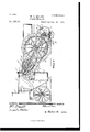
- Figure l is a side elevation of my improved street-sweeper
- Fig. 2 a top plan view thereof.
- d represents a truck-.frame with the drivers seat a and having bearings for the axles b and b2, carryingthe rear and front wheels b and b3, respectively.
- Fulcrumed on the rear axle is the inclined elevator-casing c, to the forward upper end of which is secured a chain f2, connected to the crank f3, projecting from the shaft f4.
- Said shaft is arranged at right angles to the axles and is supported in standards f5 and f, secured in turn to the truck-frame a., and is provided on its forward end with a crankhandle f7 for the purpose of operating said shaft to thus raise or lower the elevator-casing.
- Each of the clutches o comprises two members o and o2, having interlocking teeth on their adjacent faces, the one, o', being spaced from the gearwh'eel g4 by a spiral spring o3 and keyed to the shaft g5 and the other, o2, being integrally formed on the side of the sprocketwheel gs, which, as above described, is loosely journaled on the shaft.
- the member o2 of each clutch is prevented from inward movement on the shaft by a collar 04, against which said member under tension of the spring ois normally pushed by the other member of the clutch.
- the sprocket-wheels g are always kept in alinement with the' sprocket-wheels Q7.
- shaft e On the opposite end of shaft e is secured another sprocket-wheel f,operating through sprocketchain e" the sprocket-wheel Z2, which latter is mounted on the shaft h.
- Said shaft penetrates the casing and has its bearings in the sides thereof and carries within said casing a series of sprocket-wheels Zz'.
- a shaft h3 Parallel with shaft ZL and carrying a series of rollers or sprocket-wheels 71,21, arranged in alinement with the sprocket-wheels on shaft 7L' and connected therewith by the sprocketchains h2.
- Each of said sprocket-chains carries a series of Scrapers h, which are alternately arranged with and between each other.
- the shaft h3 has its bearings in the brackets h, secured to the sides of and within the casing c.
- a sweeper consisting of a truck on wheels, ⁇ an inclined elevator-casing fulcrumed on the axle of the rear wheels, a hood arranged at the lower rear end of said casin g and provided at each of its sides with a radial elongated slot, the revolving-brush-carrying shaft arranged in said hood and penetrating said slots, a fulcrumed lever on each side of the casing and furnishing bearings for the said shaft, a shorter lever on each side of and fulcrnmed on the casing and provided with an upwardlyextending arm, chains connecting said arms with the levers forming the bearings for the shaft, a wheel swiveled on each of said shorter levers, and means for revolving said brush, substantially as and for the purposes described.
- a street-sweeper provided with an elevator-casing which is vertically adjustable at its lower end, the combination of a revolublebrush-carryin g shaftjournaled near the lower end of the casing, and an adjusting mechanism therefor consisting of rearward]y-projecting levers each fulcrumed at one of its ends in the side of the casing, and provided with a substantially vertical arm and with a handle at its free end, means for adjustably supporting the free ends of the levers, chains adjustably connecting said shaft to, and depending said shaft from, the arms of said levers, and antifriction-wheels swiveled on the levers, substantially as described.
Description
(No Model.) 2 Sheets-Sheet 1.
W. s. MEARS. STREET SWEEPER.
N0. 596,331. Patented Deo. 28,1897.
WITN ESSES: INVENTUB //fam WM www. www BY m 7 ATTY's.
me Nanmsvzrzns co. Pmmumo.. wAsumarou, o. c
(No Model.)
2 Sheets-Sheet 2.
W. s. MBARS. STREET ,SWEBPER Patented Deo. 28,1897. Y
f NITE ST1-vriesv "ATENT rrrcn.
WILLIAMS. MEARS, OF SORANTON, PENNSYLVANIA, ASSIGNOR TO THE BROOKS STREET SWEEPER MANUFACTURING COMPANY, OF SAME PLACE.
STREE-T-SWEEPER.
SPECIFICATION forming part of Letters Patent No. 596,381, dated December' 28., 1897.
Application filed December 30, 1896. Serial No. 617,443. (No model.)
To @ZZ whom it may concern:
Be it known that I, WILLIAM S. MEARs, a
I citizen of the United States, residing in Scranton,county of Lackawanna,and State of Pennsylvania, have invented certain new and useful Improvements in Street-Sweepers; and I do hereby declare the following to be av full, clear, and exact description of the invention, such as will enable others skilled in the art to which it appertains to make and use the same, reference being had to the accompanying drawings, and to letters of reference marked thereon, which form a part of this specication.
The object of this invention is to improve that kind of street sweeper and cleaner having a revoluble brush, an elevating mechanism, and refuse-receptacles.-
The invention consists in the improved street-sweeper, its revolving-brush supporting and adjusting mechanism, in the refuseelevating means, and in the combination and arrangements of the various parts thereof, substantially as will be hereinafter more fully described and finally embodied in the clauses of the claim.
Referring to the accompanying drawings,in which like letters of reference indicate corresponding parts in the two views, Figure lis a side elevation of my improved street-sweeper, and Fig. 2 a top plan view thereof.
In said drawings, d represents a truck-.frame with the drivers seat a and having bearings for the axles b and b2, carryingthe rear and front wheels b and b3, respectively. Fulcrumed on the rear axle is the inclined elevator-casing c, to the forward upper end of which is secured a chain f2, connected to the crank f3, projecting from the shaft f4. Said shaft is arranged at right angles to the axles and is supported in standards f5 and f, secured in turn to the truck-frame a., and is provided on its forward end with a crankhandle f7 for the purpose of operating said shaft to thus raise or lower the elevator-casing. The lower upper portion of said casing terminates in a series of hoppers c', adapted v to be`engaged by refuse-receptacles c2, which in the present case are bags and which are arranged on a platform c3, supportedlby braces c4 and c5, secured to the truck-frame d, as clearly shown.
The lower rear end of the elevator-casing c terminates in a pan C10, adapted to receive the refuse, as will be manifest. A hood d is rigidly secured to -the rear end of said elevatorcasing and is provided at each side with a radial elongated slot d', penetrated by the shaf t d2, carryin g the revolving brush cl3. Said shaft is supported in bearings formed at the rear ends of the levers e., fulcrumed at their Vforward ends on the shaft e', having its bearings in brackets m, secured to and projecting from the casing c. On each side of the said casing and toward the rear portion thereof is fulcrumed, as at e5, a lever e4, provided with an upwardly-extending arm e3, the upper portion of which is connected by a chain e2 with the bearing for the shaft d2, which bearing, as heretofore described, is arranged at the rear end of its respective lever e. It must be stated that the chain can be lengthened and shortened as desired. A handle e6 projects rearward from each of said levers e4 and is adapted to be engaged by one of a series of stops c7, secured to and arranged on the side of the hood.
Since the hood is rigidly secured to the casing and since the stops e7 on the sides of the hood constitute supports for the rear or handle ends of the levers e4, it is obvious that the brush-shaft C37, connected to the arms e3 by chains e2, is practically depended from the arms of the levers in such a manneras to be easily adjustable. The adjustment of the shaft is of course necessary in case the brush carried thereby becomes worn, either evenly or unevenly, or in case brushes of different sizes are employed. In this connection it is to be stated that the object of the inclined elongated slot above described is to render it possible that the line of contact of the adjustable brush with the roadway shall always be the same distance from the pan or lower extremity of the casing whether a brush of large or small diameter is used.
A Wheel f', journaled in bracket f, which in turn is swiveled on its respective lever e4, is arranged on each side of the hood and below the axle d2, and forms, in connection with IOO the levers c and c", the main support for the rcvolving-brush-carrying shaft (Z2. On the said shaft (Z2 and on the ends thereof are secured the sprocket-wheels g, connected by sprocket-chains g with the sprocket-wheels g2, which latter are securely mounted on the shaft e. On 011e end of said shaft is secured a gear-wheel g3, meshing into gear-wheel g4, mounted on the parallel shaft g5, having its bearings in the brackets m. The free ends of said shafts are prevented from spreading by means of the bridge or tie gm, and the gear-wheels are thus kept in mesh. On the shaft g5 and on each side of the casing. are loosely mounted the sprocket-wheels gf", controlled by and held normally on said shaft by the clutches 0 and are connected by sprocket-chains Q7 with the sprocket-wheels g8, which latter are secured to the rearwheels b in p any desired manner. Each of the clutches o comprises two members o and o2, having interlocking teeth on their adjacent faces, the one, o', being spaced from the gearwh'eel g4 by a spiral spring o3 and keyed to the shaft g5 and the other, o2, being integrally formed on the side of the sprocketwheel gs, which, as above described, is loosely journaled on the shaft. The member o2 of each clutch is prevented from inward movement on the shaft by a collar 04, against which said member under tension of the spring ois normally pushed by the other member of the clutch. By the employment of the clutch included in the mechanism just described the sprocket-wheels g are always kept in alinement with the' sprocket-wheels Q7. On the opposite end of shaft e is secured another sprocket-wheel f,operating through sprocketchain e" the sprocket-wheel Z2, which latter is mounted on the shaft h. Said shaft penetrates the casing and has its bearings in the sides thereof and carries within said casing a series of sprocket-wheels Zz'. At the lower end of the casing is arranged a shaft h3, parallel with shaft ZL and carrying a series of rollers or sprocket-wheels 71,21, arranged in alinement with the sprocket-wheels on shaft 7L' and connected therewith by the sprocketchains h2. Each of said sprocket-chains carries a series of Scrapers h, which are alternately arranged with and between each other. The shaft h3 has its bearings in the brackets h, secured to the sides of and within the casing c.
In operation power is transmitted from the rear wheels to the shaft g5, which in turn operates the shaft c through the gear-wheels g4 and gil., The shaft c' is thus rotated in a direction opposite to that of the rear wheels and in turn transmits its motion to the shaft 7L cleaned, and should the brush be worn offthat is, become reduced in diameterthe chain e2 is lengthened, and thus the brush brought again to a proper height, as will be manifest.
Having thus described my invention, what I claim as new, and desire to secure by Letters Patent, is
1. A sweeper consisting of a truck on wheels,` an inclined elevator-casing fulcrumed on the axle of the rear wheels, a hood arranged at the lower rear end of said casin g and provided at each of its sides with a radial elongated slot, the revolving-brush-carrying shaft arranged in said hood and penetrating said slots, a fulcrumed lever on each side of the casing and furnishing bearings for the said shaft, a shorter lever on each side of and fulcrnmed on the casing and provided with an upwardlyextending arm, chains connecting said arms with the levers forming the bearings for the shaft, a wheel swiveled on each of said shorter levers, and means for revolving said brush, substantially as and for the purposes described.
2. In a street-sweeper provided with an elevator-casing which is vertically adjustable at its lower end, the combination of a revolublebrush-carryin g shaftjournaled near the lower end of the casing, and an adjusting mechanism therefor consisting of rearward]y-projecting levers each fulcrumed at one of its ends in the side of the casing, and provided with a substantially vertical arm and with a handle at its free end, means for adjustably supporting the free ends of the levers, chains adjustably connecting said shaft to, and depending said shaft from, the arms of said levers, and antifriction-wheels swiveled on the levers, substantially as described.
In testimony that I claim the foregoing I have hereunto set my hand this 7th day of October, 1896.
WILLIAM S. MEARS.
Witnesses:
ALFRED GARTNER, DUNCAN M. ROBERTSON.
IOO
Publications (1)
| Publication Number | Publication Date |
|---|---|
| US596331A true US596331A (en) | 1897-12-28 |
Family
ID=2664978
Family Applications (1)
| Application Number | Title | Priority Date | Filing Date |
|---|---|---|---|
| US596331D Expired - Lifetime US596331A (en) | mears |
Country Status (1)
| Country | Link |
|---|---|
| US (1) | US596331A (en) |
-
0
- US US596331D patent/US596331A/en not_active Expired - Lifetime
Similar Documents
| Publication | Publication Date | Title |
|---|---|---|
| US596331A (en) | mears | |
| US468458A (en) | slawson | |
| US501515A (en) | Street-sweeper | |
| US491278A (en) | Street-sweeping machine | |
| US452382A (en) | Charles ii | |
| US427185A (en) | Half to john r | |
| US525635A (en) | Thick | |
| US550014A (en) | Street-sweeper | |
| US746029A (en) | Street-sweeper. | |
| US580460A (en) | Street-sweeper | |
| US563869A (en) | Street-sweeper | |
| US548659A (en) | Street-sweeper | |
| US542808A (en) | Street-sweeper | |
| US696443A (en) | Rotary sweeper. | |
| US469030A (en) | Street-sweeper | |
| US550828A (en) | Street-sweeper | |
| US891709A (en) | Stone-gathering machine. | |
| US580603A (en) | And flint w | |
| US601598A (en) | stump | |
| US469551A (en) | Street-sweeper | |
| US651880A (en) | Street-cleaner. | |
| US799126A (en) | Combined street-sweeper and collector. | |
| US173038A (en) | Improvement in movable sugar-carriers | |
| US243358A (en) | bradley | |
| US342744A (en) | Street-sweeper |