US5951630A - Digital adder circuit - Google Patents
Digital adder circuit Download PDFInfo
- Publication number
- US5951630A US5951630A US08/783,287 US78328797A US5951630A US 5951630 A US5951630 A US 5951630A US 78328797 A US78328797 A US 78328797A US 5951630 A US5951630 A US 5951630A
- Authority
- US
- United States
- Prior art keywords
- carry
- sub
- binary number
- circuit
- input
- Prior art date
- Legal status (The legal status is an assumption and is not a legal conclusion. Google has not performed a legal analysis and makes no representation as to the accuracy of the status listed.)
- Expired - Lifetime
Links
Images


Classifications
-
- G—PHYSICS
- G06—COMPUTING; CALCULATING OR COUNTING
- G06F—ELECTRIC DIGITAL DATA PROCESSING
- G06F7/00—Methods or arrangements for processing data by operating upon the order or content of the data handled
- G06F7/38—Methods or arrangements for performing computations using exclusively denominational number representation, e.g. using binary, ternary, decimal representation
- G06F7/48—Methods or arrangements for performing computations using exclusively denominational number representation, e.g. using binary, ternary, decimal representation using non-contact-making devices, e.g. tube, solid state device; using unspecified devices
- G06F7/50—Adding; Subtracting
- G06F7/505—Adding; Subtracting in bit-parallel fashion, i.e. having a different digit-handling circuit for each denomination
- G06F7/506—Adding; Subtracting in bit-parallel fashion, i.e. having a different digit-handling circuit for each denomination with simultaneous carry generation for, or propagation over, two or more stages
- G06F7/507—Adding; Subtracting in bit-parallel fashion, i.e. having a different digit-handling circuit for each denomination with simultaneous carry generation for, or propagation over, two or more stages using selection between two conditionally calculated carry or sum values
-
- G—PHYSICS
- G06—COMPUTING; CALCULATING OR COUNTING
- G06F—ELECTRIC DIGITAL DATA PROCESSING
- G06F2207/00—Indexing scheme relating to methods or arrangements for processing data by operating upon the order or content of the data handled
- G06F2207/38—Indexing scheme relating to groups G06F7/38 - G06F7/575
- G06F2207/3804—Details
- G06F2207/386—Special constructional features
- G06F2207/3876—Alternation of true and inverted stages
Definitions
- This invention relates to the field of data processing. More particularly, this invention relates to digital adder circuits used within data processing systems.
- Addition is one of the most important arithmetic operations that is frequently performed within data processing systems.
- a problem with producing high speed adder circuits is that the high order bits of the result are dependent upon the carry out values from the low order bits. The consequence of this is that addition operations tend to be relatively slow. It is a constant aim within data processing systems that they should operate as rapidly as possible and to this end considerable effort has been expended over many years in designing and developing adder circuits that are capable of operating at high speed.
- the present invention provides an adder circuit for adding a first binary number and a second binary number, said adder circuit comprising:
- a carry evaluating circuit for evaluating a carry production control signal representing a sum of a block of corresponding bits of said first binary number and said second binary number and an input carry value to said block, said carry production control signal comprising two signals V and W that can each have a value of either P or Q, said carry production control signal encoding a carry result from said sum in accordance with:
- V ⁇ W represents a carry propagate whereby said carry result equals said input carry value
- the invention provides an encoding for the carry production control signal that is capable of being produced with fewer circuit elements and with fewer logical layers resulting in a faster, smaller and more power efficient circuit.
- the values P and Q that the two signals V and W can take could have a variety of absolute values and could be in true or inverted form.
- the carry evaluating circuit that performs the encoding set out above would typically occur many times within an adder circuit as a whole. Depending upon where in the adder circuit a particular carry evaluating circuit is positioned it will receive as its input either bits from the first binary number and the second binary number or bits comprising previously evaluated carry production control signals from upstream in the circuit. More particularly, in preferred embodiments of the invention said carry evaluating circuit is responsive to two pairs of input signals (a 1 , b 1 ) and (a 2 , b 2 ) that comprise one of two respective pairs of bits of said first binary number and said second binary number or two previously evaluated carry production control signals and V and W are given by:
- the encoding performed by the carry evaluating circuit is one that is well suited to efficient implementation in a plurality of static CMOS logic gates.
- the encoding is also suitable for embodiment by a plurality of dynamic CMOS logic gates.
- a preferred adder circuit structure within which the above described techniques may be employed is one comprising:
- a carry binary number determining circuit responsive to said first binary number and said second binary number for determining a carry binary number composed of carry bits of a sum of said first binary number and said second binary number, said carry binary number determining circuit having a plurality of circuit stages operating in series to determine said carry binary number, each circuit stage serving to partially resolve said carry binary number and at least one circuit stage including at least one of said carry bit evaluating circuits generating a carry control production signal that is passed between said circuit stages as an input signal to a next circuit stage;
- a combinatorial logic circuit responsive to respective corresponding bits of said first binary number, said second binary number and said carry binary number to generate a corresponding bit of a result binary number.
- the adder circuit of the present invention is particularly well suited for use within an integrated circuit microprocessor.
- the present invention provides a method of operating an adder circuit for adding a first binary number and a second binary number, said method comprising the steps of:
- V ⁇ W represents a carry propagate whereby said carry result equals said input carry value
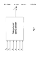
- FIG. 1 illustrates a two-input-pair carry evaluation circuit
- FIG. 2 illustrates a 16 bit carry binary number evaluating system incorporating the carry evaluation circuits of FIG. 1;
- FIG. 3 illustrates a three-input-pair carry evaluation circuit
- FIG. 4 illustrates a 9 bit carry binary number evaluation system incorporating the carry evaluation circuits of FIG. 3;
- FIG. 5 illustrates a static CMOS embodiment of the circuit of FIG. 1
- FIG. 6 illustrates a static CMOS embodiment of the circuit of FIG. 3
- FIG. 7 illustrates the interconnections between four-input-pair carry evaluation circuits being used to calculate the most significant bit of a 32 bit carry binary number
- FIG. 8 corresponds to FIG. 7 except that the second most significant bit is being evaluated.
- FIG. 9 illustrates a 4-input pair carry evaluation circuit
- FIG. 10 illustrates a 16-bit adder using 4-input pair carry evaluation circuits
- FIGS. 11 and 12 illustrate CMOS circuit implementations of 4-input pair carry evaluating circuits
- FIG. 13 illustrates a conventional adder circuit
- FIG. 14 illustrates an adder circuit incorporating 4-input pair carry evaluating circuits.
- the general concept of carry arbitration will be considered first.
- the carry c i+1 is evaluated by adding two 1-bit binary numbers a i and b i .
- the first case where there is an output carry request, arises when both operand bits are equal.
- a 1-carry request occurs if both inputs are 1, whereas a 0-carry request if both inputs are 0.
- the second case where there is no output carry request, arises when the operand bits have different values. See Table 1 in which the letter u indicates there is no output carry request.
- FIG. 1 shows a 2-input-pair carry arbiter (carry evaluation circuit).
- the input pair (a i , b i ) can make a non-maskable carry request (non-maskable has the meaning that this request must always be acknowledged by the output carry c i+1 ).
- the input pair (a j , b j ) can make a maskable carry request (maskable has the meaning that this request may be masked by a non-maskable carry request). Only when there is no non-maskable carry request from the input pair (a i , b i ), is a maskable carry request from the input pair (a j , b j ) acknowledged by the output carry c i +1. This is illustrated in Table 2.
- the output carry c i+1 can be encoded using two wires (v i , w i ) as shown in Table 3.
- the signals on the two wires constitute the carry production control signal.
- Tables 2 and 3 The following equations satisfy Tables 2 and 3:
- FIG. 2 A 16-bit fast carry computation using 2-input-pair carry arbiters is shown in FIG. 2, which illustrates that the scheme is regular.
- Each node in FIG. 2 is a 2-input-bit carry arbiter.
- each node can be considered to "vote" on the result to be passed up to the next level in the circuit.
- the node can indicate a carry generate (1, 1) (a vote yes), a carry kill (0, 0) (a vote no) or a carry propagate (0, 1) or (1, 0) (an abstention).
- this arbitration is carried out between bits of the input operands, and at higher level between the results of previously determined arbitrations.
- the system of FIG. 2 is different from the scheme proposed by Brent and Kung as mentioned earlier.
- the computation logic needed for g i (the generate signal) and p i (the propagate signal) in the Brent and Kung adders is not necessary in the present scheme. This results in fewer layers of logic being required and hence high-speed carry generation.
- the two pairs (g i , p i ) and (g j ,p j ) generated from the input pairs (a i , b i ) and (a j , b j ) can be viewed as new input pairs.
- the new input pair (g i , p i ) makes a 0-carry request when g i and p i are both 0, a 1-carry request when g i is 1, and no carry request when p i is 1. Note that g i and p i are mutually exclusive as shown in Table 4.
- the output carry c i+1 could be encoded using two wires (v i , w i ) as shown in Table 5.
- the following equations satisfy Tables 4 and 5:
- Equation (2) above is the key idea of the well known Brent and Kung adders.
- the logic computation for the carry generate g i and the carry propagate p i is wasteful except for understanding how the carries are generated and propagated.
- a 3-input-pair carry arbiter in accordance with the present scheme is shown in FIG. 3.
- the input pair (a i , b i ) can make a non-maskable carry request.
- the input pairs (a j , b j ) and (a k , b k ) can both make a maskable carry request at the same time.
- the input pair (a j , b j ) has priority over the input pair (a k , b k ).
- FIG. 4 shows a 9-bit carry computation using 3-input-pair carry arbiters, which results in only two layers of logic and hence high-speed carry generation.
- the addition of n-bit binary numbers using 3-input-pair carry arbiters can be performed in time proportional to O(log 3 n), and therefore is more efficient than using 2-input-pair carry arbiters where the computation time is O(log 2 n).
- carry arbiters with any numbers of input pairs can be derived.
- carry arbiters with more than 4 input pairs are not usually of interest. Firstly, too many series transistors are needed to implement these arbiters, which leads to inefficient CMOS designs. Secondly, the arbiter cell layout becomes too large for the bit slice of a datapath.
- FIG. 5 shows a static CMOS implementation of the 2-input-pair carry arbiter. Note that the outputs v i and w i are complemented signals. However, the arbiter is quite symmetrical and implementing the next stage in inverse logic is straight forward. The signals through two arbiters are naturally positive-true, so no inverters are needed.
- FIG. 6 shows a static CMOS implementation of the 3-input-pair carry arbiter.
- 3- or 4-input-pair carry arbiters may be advantageous if dynamic CMOS techniques are used, in which case either the pull-up or pull-down parts of the circuits of FIG. 3 may be used.
- Extending the 3-input-pair circuit of FIG. 6 to produce a 4-input-pair or higher circuit is achieved by symmetrically extending in stages in an analogous manner to the extension between FIGS. 5 and 6.
- the verification of design may be carried out formally by considering an n-bit adder based on 2-input-pair arbiters as an example, Let a n , a n-1 , . . . , a 1 and b n , b n-1 , . . . , b 1 be n-bit binary numbers without carries c n , c n-n , . . . , c 1 , and let c 0 be the input carry bit.
- the operator o can be proved to be associative. Therefore, v i and w i can be computed in any order from the given input values. This provides the foundation for using tree structures to generate carries. Note that the operator o is not commutative, which implies the priorities of different input pairs.
- FIG. 7 shows a part of a 32-bit adder design that generates the carry for the 32nd bit.
- 4-input-pair carry arbiters are used in the first and second rows (from the bottom), whereas 2-input-pair arbiters are employed in the third row.
- the carry computation goes through only three logic layers.
- FIG. 8 shows the part of the circuit that generates the 31st bit carry. Analogous circuit (interconnections) to those shown in FIGS. 7 and 8 are used for the other bits of the carry result. Once a carry bit has been determined (i.e. the carry-in and structure result a generate or a kill, with propagate not being possible at that point), then a single signal wire may be used to pass that result to higher levels.
- the final row is a sum circuit that operates to XOR the input operands and the carry result.
- the carry out from the adder of FIGS. 7 and 8 can be achieved by expanding the three rows of carry arbiters to include a bit 32 and then puts a two bit arbiter in position 32 in the fourth row with inputs from positions 0 and 32 of the previous row.
- the present scheme takes only 1.85 ns to complete a 32-bit carry computation using a 0.6 ⁇ m CMOS process technology.
- the carry c i is evaluated by adding two 1-bit numbers a i and b i as shown in Table 1 above.
- a 1-carry request occurs if both inputs are 1, whereas a 0-carry request if both inputs are 0.
- the letter u indicates there is no carry request.
- the other three input pairs (a 2 , b 2 ), (a 1 , b 1 ) and (a 0 , b 0 ) can make maskable carry requests, where maskable means that carry requests from these three input pairs may be masked by the input pair (a 3 , b 3 ).
- the input pair (a 2 , b 2 ) has higher priority than the input pairs (a 1 , b 1 ) and (a 0 , b 0 ).
- the input pair (a 0 , b 0 ) has the lowest priority.
- carry arbiters with any number of ways can be derived.
- the carries can be generated quickly by using carry arbiters combined into a tree structure which exploits the associativity of the carry computation.
- FIG. 10 illustrates 16-bit carry computation base on the carry arbitration.
- the solid dots represents carry arbiters.
- the addition of n-bit numbers using m-way carry arbiters can be performed in a time proportional to O(log m n).
- the carry request out c can be encoded using two wires (aa, bb) as shown in Table 8. Equations 6 and 7 give the behavior defined by Tables 7 and 8.
- FIG. 11 shows a direct dynamic CMOS implementation of the four-way carry arbiter according to the above equations.
- the operation of the circuit is such that the nodes n1 and n2 are precharged high when the inputs a 3 and b 3 are low during the reset phase of the control handshake and will conditionally discharge during the evaluation phase.
- the buffers are used to maintain drive strength.
- FIG. 12 gives a modified version of the four-way carry arbiter.
- every input pair (a i , b i ) takes one of the three values (0 0), (1 1) and (1 0), and (0 1) has already been transformed to (1 0).
- the reasons are twofold. Firstly, it is easy to layout the modified circuit into the bit pitch (21.5 ⁇ m in this embodiment) of a datapath and it is about 300 ps faster than the direct implementation.
- the outputs aa and bb have new meaning. If the outputs aa and bb have different values, this means there are no carry requests from the inputs as described previously. However, we can take another view of a four-way carry arbiter.
- one of the outputs aa and bb can be viewed as the carry out generated with a zero carry-in and the other is with a one carry-in.
- the direct implementation does not distinguish which is the carry out generated with a zero carry-in and which with a one carry-in.
- the modified circuit gives exactly the outputs aa as the carry out generated with a one carry-in and the output bb as the carry out generated with a zero carry-in. This results in a significant reduction of chip area (see below) and is an important feature of this embodiment.
- the use of the modified implementation needs the input conversion from (0 1) to (1 0). Fortunately this causes no problem; the conversion is simple. It consists of one 2-input NAND and one 2-input NOR gate per bit. For practical reasons, gates are normally necessary anyway to isolate the signals from the main input bases. The difference here is that NAND and NOR gates are used instead of inverters. If two input buses are designed using a precharge structure, the outputs after NAND and NOR gates are naturally low (required in the dynamic implementation) when the buses are precharged high. Furthermore, these NAND and NOR gates can be reused for logic operations in an ALU design.
- FIG. 13 shows a conventional adder design using the carry select scheme.
- the inputs are divided into d-bit groups.
- Two adders are needed per group.
- One is an adder with a zero carry-in and the other with a one carry-in.
- the carry generator is responsible for generating the boundary carries for all groups, which are then used to select the appropriate sum using a multiplexer.
- a design decision must be made to chose appropriate groups in order to balance the delays of both the carry generator and the group adders. If the group adders are made too long, then the decreasing delays in the carry generator are exceeded by the increasing delays of the group adders. If the group adders are made too short, the logic depth of the carry generator increases and its delay determines the total adder delay.
- FIG. 14 A block diagram of an 80-bit adder in accordance with one embodiment of the present invention is shown in FIG. 14.
- the whole adder is visualized (but not divided) as consisting of five 16-bit groups.
- the first row is the conversion circuit, which contains 2-input NAND and NOR gates.
- the second and third rows are the four-way arbiters which produce the carries within each group and have the form discussed previously.
- the fourth row produces two intermediate sums with a zero carry-in and a one carry-in.
- the final row is multiplexers which select the final sum result and three carry arbiters which generate the boundary carries c 16 , c 32 , c 48 and c 64 .
- the carries of the 16 least significant bits have already been generated after two rows of the carry computation.
- the adder is designed in a 0.5 ⁇ m triple metal CMOS technology.
- the layout has a regular structure and uniform fan-in and fan-out loadings and hence is very compact.
- Post-layout HSPICE simulation shows that the adder takes 3.5 ns to complete an 80-bit addition.
- the characteristics of this adder are summarized in Table 9.
- a carry arbitration scheme has been developed in which the carry is generated using a prioritized arbitration of several carry requests based on the associativity of the carry computation.
- the proposed scheme not only leads to high speed adders due to the few layers of logic required, but also offers a regular and compact layout and uniform fan-in and fan-out loadings.
- a dynamic CMOS implementation of a four-way carry arbiter has been devised and modified.
- the modified version uses double meanings. If the outputs aa and bb are equal, it means that the carry has been generated. If they are different, it means that the output aa is the carry out generated with a one carry-in and the output bb with a zero carry-in.
Abstract
Description
V=a.sub.2.b.sub.2 +(a.sub.2 +b.sub.2).a.sub.1 ;
W=a.sub.2.b.sub.2 +(a.sub.2 +b.sub.2).b.sub.1.
              TABLE 1
______________________________________
         a.sub.i, b.sub.i
              c.sub.i+1
______________________________________
         0 0  0
         1 1  1
         0 1  u
         1 0  u
______________________________________
              TABLE 2
______________________________________
a.sub.i, b.sub.i
                a.sub.j, b.sub.j
                          C.sub.i+1
______________________________________
0 0             -- --     0
1 1             -- --     1
0 1 (or 1 0)    0 0       0
0 1 (or 1 0)    1 1       1
0 1 (or 1 0)    0 1 (or 1 0)
                          u
______________________________________
              TABLE 3
______________________________________
v.sub.i  = a.sub.i b.sub.i  + (a.sub.i  + b.sub.i) a.sub.j
w.sub.i  = a.sub.i b.sub.i  + (a.sub.i  + b.sub.i) b.sub.j
                               (1)
         c.sub.i+1
             v.sub.i, w.sub.i
______________________________________
         0   0 0
         1   1 1
         u   0 1
         u   1 0
______________________________________
              TABLE 4
______________________________________
g.sub.i, p.sub.i g.sub.j, P.sub.j
                        c.sub.i+1
______________________________________
0 0              -- --  0
1 0              -- --  1
0 1              0 0    0
0 1              1 0    1
0 1              0 1    u
______________________________________
              TABLE 5
______________________________________
v.sub.i  = g.sub.i  + p.sub.i g.sub.j
w.sub.i  = p.sub.i p.sub.j     (2)
         c.sub.i+1
             v.sub.i, w.sub.i
______________________________________
         0   0 0
         1   1 0
         u   0 1
______________________________________
              TABLE 6
______________________________________
v.sub.i  = a.sub.i b.sub.i  + (a.sub.i  + b.sub.i)(a.sub.j b.sub.j  +
(a.sub.j  + b.sub.j)a.sub.k)
v.sub.i  = a.sub.i b.sub.i  + (a.sub.i  + b.sub.i)(a.sub.j b.sub.j  +
(a.sub.j  + b.sub.j)b.sub.k)   (3)
a.sub.i, b.sub.i
          a.sub.j, b.sub.j
                         a.sub.k, b.sub.k
                                   c.sub.i+1
______________________________________
0 0       -- --          -- --     0
1 1       -- --          -- --     1
0 1 (or 1 0)
          0 0            -- --     0
0 1 (or 1 0)
          1 1            -- --     1
0 1 (or 1 0)
          0 1 (or 1 0)   0 0       0
0 1 (or 1 0)
          0 1 (or 1 0)   1 1       1
0 1 (or 1 0)
          0 1 (or 1 0)   0 1 (or 1 0)
                                   u
______________________________________
              TABLE 7
______________________________________
a.sub.3,b.sub.3
          a.sub.2,b.sub.2
                  a.sub.1,b.sub.1
                               a.sub.0,b.sub.0
                                     c
______________________________________
00        --      --           --    0
11        --      --           --    1
01 or 10  00      --           --    0
01 or 10  11      --           --    1
01 or 10  01 or 10
                  00           --    0
01 or 10  01 or 10
                  11           --    1
01 or 10  01 or 10
                  01 or 10     00    0
01 or 10  01 or 10
                  01 or 10     11    1
01 or 10  01 or 10
                  01 or 10     01 or 10
                                     u
______________________________________
              TABLE 8
______________________________________
aa = a.sub.3 b.sub.3  + (a.sub.3  + b.sub.3)(a.sub.2 b.sub.2  + (a.sub.2
+ b.sub.2)(a.sub.1 b.sub.1  + (a.sub.1  +b.sub.1)a.sub.0))
                               (6)
bb = a.sub.3 b.sub.3  + (a.sub.3  + b.sub.3)(a.sub.2 b.sub.2  + (a.sub.2
+ b.sub.2)(a.sub.1 b.sub.1  + (a.sub.1  +b.sub.1)b.sub.0))
                               (7)
         c   aa,bb
______________________________________
         0   0 0
         1   1 1
         u   0 1
         u   1 0
______________________________________
              TABLE 9
______________________________________
Technology    0.5 μm triple metal CMOS
Power Supply  3.3 Volt
Addition Time 3.5 ns
Active Area   1720 μm × 124 μm
Transistor Count
              2546
Transistor Density
              12 k/mm.sup.2
______________________________________
Claims (17)
V=a.sub.2.b.sub.2 +(a.sub.2 +b.sub.2).a.sub.1 ;
W=a.sub.2.b.sub.2 +(a.sub.2 +b.sub.2).b.sub.1.
V=a.sub.3.b.sub.3 +(a.sub.3 +b.sub.3)(a.sub.2.b.sub.2 +(a.sub.2 +b.sub.2).a.sub.1);
W=a.sub.3.b.sub.3 +(a.sub.3 +b.sub.3)(a.sub.2.b.sub.2 +(a.sub.2 +b.sub.2).b.sub.1).
V=a.sub.4.b.sub.4 +(a.sub.4 +b.sub.4)(a.sub.3.b.sub.3 +(a.sub.3 +b.sub.3)(a.sub.2.b.sub.2 +(a.sub.2 +b.sub.2).a.sub.1));
W=a.sub.4.b.sub.4 +(a.sub.4 +b.sub.4)(a.sub.3.b.sub.3 +(a.sub.3 +b.sub.3)(a.sub.2.b.sub.2 +(a.sub.2 +b.sub.2)..sub.1)).
V=f.sup.N.sub.V (a.sub.N, b.sub.N, . . . , a.sub.1, b.sub.1);
W=f.sup.N.sub.W (a.sub.N, b.sub.N, . . . , a.sub.1, b.sub.1);
f.sup.i.sub.V (a.sub.i, b.sub.i, . . . , a.sub.1, b.sub.1)=a.sub.i.b.sub.i +(a.sub.i +b.sub.i).f.sup.i-1.sub.V ;
f.sup.i.sub.W (a.sub.i, b.sub.i, . . . , a.sub.1, b.sub.1)=a.sub.i.b.sub.i +(a.sub.i +b.sub.i).f.sup.i-1.sub.W.
Applications Claiming Priority (2)
| Application Number | Priority Date | Filing Date | Title |
|---|---|---|---|
| GB9620526 | 1996-10-02 | ||
| GB9620526A GB2317971B (en) | 1996-10-02 | 1996-10-02 | Digital adder circuit |
Publications (1)
| Publication Number | Publication Date |
|---|---|
| US5951630A true US5951630A (en) | 1999-09-14 |
Family
ID=10800811
Family Applications (1)
| Application Number | Title | Priority Date | Filing Date |
|---|---|---|---|
| US08/783,287 Expired - Lifetime US5951630A (en) | 1996-10-02 | 1997-01-10 | Digital adder circuit |
Country Status (10)
| Country | Link |
|---|---|
| US (1) | US5951630A (en) |
| EP (1) | EP1008033B1 (en) |
| JP (1) | JP2001501341A (en) |
| KR (1) | KR20000048818A (en) |
| CN (1) | CN1232561A (en) |
| DE (1) | DE69708160D1 (en) |
| GB (1) | GB2317971B (en) |
| IL (1) | IL128178A0 (en) |
| TW (1) | TW313652B (en) |
| WO (1) | WO1998014864A1 (en) |
Cited By (3)
| Publication number | Priority date | Publication date | Assignee | Title |
|---|---|---|---|---|
| KR20000054275A (en) * | 2000-05-30 | 2000-09-05 | 장주욱 | A high speed parallel adder which reconfigures itself for fast processing of input |
| US20030074385A1 (en) * | 2001-09-28 | 2003-04-17 | Jianwei Liu | Providing a fast adder for processor based devices |
| US7231414B1 (en) * | 2000-02-09 | 2007-06-12 | Hewlett-Packard Development Company, L.P. | Apparatus and method for performing addition of PKG recoded numbers |
Families Citing this family (6)
| Publication number | Priority date | Publication date | Assignee | Title |
|---|---|---|---|---|
| US7921148B2 (en) * | 2006-08-09 | 2011-04-05 | Infineon Technologies Ag | Standard cell for arithmetic logic unit and chip card controller |
| CN101201731B (en) * | 2008-02-15 | 2010-08-18 | 刘杰 | Binary digit subtracter |
| US8521801B2 (en) * | 2008-04-28 | 2013-08-27 | Altera Corporation | Configurable hybrid adder circuitry |
| US9785405B2 (en) * | 2015-05-29 | 2017-10-10 | Huawei Technologies Co., Ltd. | Increment/decrement apparatus and method |
| CN105045556B (en) * | 2015-07-09 | 2018-01-23 | 合肥工业大学 | A kind of dynamic static mixing type adder |
| CN113642280A (en) * | 2020-04-27 | 2021-11-12 | 中国科学院上海微系统与信息技术研究所 | Layout method of superconducting integrated circuit |
Citations (10)
| Publication number | Priority date | Publication date | Assignee | Title |
|---|---|---|---|---|
| US4099248A (en) * | 1977-01-28 | 1978-07-04 | Sperry Rand Corporation | One's complement subtractive arithmetic unit utilizing two's complement arithmetic circuits |
| US5134579A (en) * | 1989-09-05 | 1992-07-28 | Sony Corporation | Digital adder circuit |
| US5278783A (en) * | 1992-10-30 | 1994-01-11 | Digital Equipment Corporation | Fast area-efficient multi-bit binary adder with low fan-out signals |
| US5329477A (en) * | 1991-09-11 | 1994-07-12 | Kabushiki Kaisha Toshiba | Adder circuit having carry signal initializing circuit |
| EP0626638A1 (en) * | 1993-05-03 | 1994-11-30 | Motorola, Inc. | A one's complement adder and method of operation |
| US5465224A (en) * | 1993-11-30 | 1995-11-07 | Texas Instruments Incorporated | Three input arithmetic logic unit forming the sum of a first Boolean combination of first, second and third inputs plus a second Boolean combination of first, second and third inputs |
| US5485411A (en) * | 1993-11-30 | 1996-01-16 | Texas Instruments Incorporated | Three input arithmetic logic unit forming the sum of a first input anded with a first boolean combination of a second input and a third input plus a second boolean combination of the second and third inputs |
| US5493524A (en) * | 1993-11-30 | 1996-02-20 | Texas Instruments Incorporated | Three input arithmetic logic unit employing carry propagate logic |
| US5499203A (en) * | 1992-09-27 | 1996-03-12 | Grundland; Nathan | Logic elements for interlaced carry/borrow systems having a uniform layout |
| US5596763A (en) * | 1993-11-30 | 1997-01-21 | Texas Instruments Incorporated | Three input arithmetic logic unit forming mixed arithmetic and boolean combinations |
-
1996
- 1996-10-02 GB GB9620526A patent/GB2317971B/en not_active Expired - Lifetime
- 1996-12-18 TW TW085115653A patent/TW313652B/en not_active IP Right Cessation
-
1997
- 1997-01-10 US US08/783,287 patent/US5951630A/en not_active Expired - Lifetime
- 1997-07-04 IL IL12817897A patent/IL128178A0/en unknown
- 1997-07-04 EP EP97930628A patent/EP1008033B1/en not_active Expired - Lifetime
- 1997-07-04 KR KR1019990702813A patent/KR20000048818A/en not_active Application Discontinuation
- 1997-07-04 DE DE69708160T patent/DE69708160D1/en not_active Expired - Lifetime
- 1997-07-04 CN CN97198461A patent/CN1232561A/en active Pending
- 1997-07-04 WO PCT/GB1997/001812 patent/WO1998014864A1/en not_active Application Discontinuation
- 1997-07-04 JP JP10516294A patent/JP2001501341A/en active Pending
Patent Citations (10)
| Publication number | Priority date | Publication date | Assignee | Title |
|---|---|---|---|---|
| US4099248A (en) * | 1977-01-28 | 1978-07-04 | Sperry Rand Corporation | One's complement subtractive arithmetic unit utilizing two's complement arithmetic circuits |
| US5134579A (en) * | 1989-09-05 | 1992-07-28 | Sony Corporation | Digital adder circuit |
| US5329477A (en) * | 1991-09-11 | 1994-07-12 | Kabushiki Kaisha Toshiba | Adder circuit having carry signal initializing circuit |
| US5499203A (en) * | 1992-09-27 | 1996-03-12 | Grundland; Nathan | Logic elements for interlaced carry/borrow systems having a uniform layout |
| US5278783A (en) * | 1992-10-30 | 1994-01-11 | Digital Equipment Corporation | Fast area-efficient multi-bit binary adder with low fan-out signals |
| EP0626638A1 (en) * | 1993-05-03 | 1994-11-30 | Motorola, Inc. | A one's complement adder and method of operation |
| US5465224A (en) * | 1993-11-30 | 1995-11-07 | Texas Instruments Incorporated | Three input arithmetic logic unit forming the sum of a first Boolean combination of first, second and third inputs plus a second Boolean combination of first, second and third inputs |
| US5485411A (en) * | 1993-11-30 | 1996-01-16 | Texas Instruments Incorporated | Three input arithmetic logic unit forming the sum of a first input anded with a first boolean combination of a second input and a third input plus a second boolean combination of the second and third inputs |
| US5493524A (en) * | 1993-11-30 | 1996-02-20 | Texas Instruments Incorporated | Three input arithmetic logic unit employing carry propagate logic |
| US5596763A (en) * | 1993-11-30 | 1997-01-21 | Texas Instruments Incorporated | Three input arithmetic logic unit forming mixed arithmetic and boolean combinations |
Non-Patent Citations (6)
| Title |
|---|
| Brent, Richard P. et al., "A Regular Layout for Parallel Adders", IEEE Transactions on Computers, vol. C-31, No. 3, Mar., 1982, pp. 260-264. |
| Brent, Richard P. et al., A Regular Layout for Parallel Adders , IEEE Transactions on Computers, vol. C 31, No. 3, Mar., 1982, pp. 260 264. * |
| Dobberpuhl, Daniel W. et al., "A 200-MHz 64-b Dual-Issue CMOS Microprocessor", IEEE Journal of Solid-State Circuits, vol. 27, No. 11, Nov., 1992, pp. 1555-1564. |
| Dobberpuhl, Daniel W. et al., A 200 MHz 64 b Dual Issue CMOS Microprocessor , IEEE Journal of Solid State Circuits, vol. 27, No. 11, Nov., 1992, pp. 1555 1564. * |
| Doran, R. W., "Variants of an Improved Carry Look-Ahead Adder", IEEE Transaction on Computers, vol. 37, No. 9, Sep., 1988, pp. 1110-1113. |
| Doran, R. W., Variants of an Improved Carry Look Ahead Adder , IEEE Transaction on Computers, vol. 37, No. 9, Sep., 1988, pp. 1110 1113. * |
Cited By (4)
| Publication number | Priority date | Publication date | Assignee | Title |
|---|---|---|---|---|
| US7231414B1 (en) * | 2000-02-09 | 2007-06-12 | Hewlett-Packard Development Company, L.P. | Apparatus and method for performing addition of PKG recoded numbers |
| KR20000054275A (en) * | 2000-05-30 | 2000-09-05 | 장주욱 | A high speed parallel adder which reconfigures itself for fast processing of input |
| US20030074385A1 (en) * | 2001-09-28 | 2003-04-17 | Jianwei Liu | Providing a fast adder for processor based devices |
| US6954773B2 (en) | 2001-09-28 | 2005-10-11 | Intel Corporation | Providing an adder with a conversion circuit in a slack propagation path |
Also Published As
| Publication number | Publication date |
|---|---|
| GB9620526D0 (en) | 1996-11-20 |
| IL128178A0 (en) | 1999-11-30 |
| GB2317971A (en) | 1998-04-08 |
| KR20000048818A (en) | 2000-07-25 |
| WO1998014864A1 (en) | 1998-04-09 |
| TW313652B (en) | 1997-08-21 |
| JP2001501341A (en) | 2001-01-30 |
| EP1008033A1 (en) | 2000-06-14 |
| CN1232561A (en) | 1999-10-20 |
| EP1008033B1 (en) | 2001-11-07 |
| GB2317971B (en) | 2000-12-06 |
| DE69708160D1 (en) | 2001-12-13 |
Similar Documents
| Publication | Publication Date | Title |
|---|---|---|
| Parmar et al. | Design of high speed hybrid carry select adder | |
| Wang et al. | Fast adders using enhanced multiple-output domino logic | |
| US4623982A (en) | Conditional carry techniques for digital processors | |
| US6269386B1 (en) | 3X adder | |
| Rakesh et al. | A comprehensive review on the VLSI design performance of different Parallel Prefix Adders | |
| US5951630A (en) | Digital adder circuit | |
| US20020143841A1 (en) | Multiplexer based parallel n-bit adder circuit for high speed processing | |
| Akila et al. | Implementation of high speed Vedic multiplier using modified adder | |
| US5471414A (en) | Fast static CMOS adder | |
| Parameshwara | Approximate full adders for energy efficient image processing applications | |
| US7024445B2 (en) | Method and apparatus for use in booth-encoded multiplication | |
| Ghafari et al. | A new high-speed and low area efficient pipelined 128-bit adder based on modified carry look-ahead merging with Han-Carlson tree method | |
| US5126965A (en) | Conditional-sum carry structure compiler | |
| Ykuntam et al. | Design of 32-bit carry select adder with reduced area | |
| US6954773B2 (en) | Providing an adder with a conversion circuit in a slack propagation path | |
| US6782406B2 (en) | Fast CMOS adder with null-carry look-ahead | |
| JPH0366693B2 (en) | ||
| Lutz et al. | Comparison of two's complement numbers | |
| US5018094A (en) | Dual incrementer | |
| EP0564137B1 (en) | Parallelized borrow look ahead subtractor | |
| JPH056892B2 (en) | ||
| Wang et al. | Area-time analysis of carry lookahead adders using enhanced multiple output domino logic | |
| US6631393B1 (en) | Method and apparatus for speculative addition using a limited carry | |
| Mohan et al. | Comments on" Breaking the 2n-bit carry-propagation barrier in residue to binary conversion for the [2/sup n/-1, 2/sup n/, 2/sup n/+ 1] moduli set" and author's reply | |
| Govindarajulu et al. | Design of Energy-Efficient and High-Performance VLSI Adders |
Legal Events
| Date | Code | Title | Description |
|---|---|---|---|
| AS | Assignment |
Owner name: ADVANCED RISC MACHINES LIMITED, UNITED KINGDOM Free format text: ASSIGNMENT OF ASSIGNORS INTEREST;ASSIGNOR:LIU, JIANWEI;REEL/FRAME:008395/0662 Effective date: 19961106 |
|
| AS | Assignment |
Owner name: ARM LIMITED, UNITED KINGDOM Free format text: CHANGE OF NAME;ASSIGNOR:ADVANCED RISC MACHINES LIMITED;REEL/FRAME:009289/0569 Effective date: 19980521 |
|
| STCF | Information on status: patent grant |
Free format text: PATENTED CASE |
|
| AS | Assignment |
Owner name: ARM LIMITED, UNITED KINGDOM Free format text: ASSIGNMENT OF ASSIGNORS INTEREST;ASSIGNOR:ARM LIMITED;REEL/FRAME:010742/0340 Effective date: 20000320 |
|
| FPAY | Fee payment |
Year of fee payment: 4 |
|
| FPAY | Fee payment |
Year of fee payment: 8 |
|
| FPAY | Fee payment |
Year of fee payment: 12 |