US5950020A - Folding photographic method and apparatus - Google Patents
Folding photographic method and apparatus Download PDFInfo
- Publication number
- US5950020A US5950020A US09/008,644 US864498A US5950020A US 5950020 A US5950020 A US 5950020A US 864498 A US864498 A US 864498A US 5950020 A US5950020 A US 5950020A
- Authority
- US
- United States
- Prior art keywords
- housing
- lens
- camera
- housing means
- focal length
- Prior art date
- Legal status (The legal status is an assumption and is not a legal conclusion. Google has not performed a legal analysis and makes no representation as to the accuracy of the status listed.)
- Expired - Fee Related
Links
Images


Classifications
-
- G—PHYSICS
- G03—PHOTOGRAPHY; CINEMATOGRAPHY; ANALOGOUS TECHNIQUES USING WAVES OTHER THAN OPTICAL WAVES; ELECTROGRAPHY; HOLOGRAPHY
- G03B—APPARATUS OR ARRANGEMENTS FOR TAKING PHOTOGRAPHS OR FOR PROJECTING OR VIEWING THEM; APPARATUS OR ARRANGEMENTS EMPLOYING ANALOGOUS TECHNIQUES USING WAVES OTHER THAN OPTICAL WAVES; ACCESSORIES THEREFOR
- G03B17/00—Details of cameras or camera bodies; Accessories therefor
- G03B17/48—Details of cameras or camera bodies; Accessories therefor adapted for combination with other photographic or optical apparatus
- G03B17/50—Details of cameras or camera bodies; Accessories therefor adapted for combination with other photographic or optical apparatus with both developing and finishing apparatus
- G03B17/52—Details of cameras or camera bodies; Accessories therefor adapted for combination with other photographic or optical apparatus with both developing and finishing apparatus of the Land type
Definitions
- the present invention relates broadly to imaging apparatus and methods and, in particular, to improved folding cameras, preferably, of the self-developing type having multiple focal lengths.
- Folding cameras of the self-developing type are well known in the art.
- U.S. Pat. No. 4,452,519 issued Jun. 5, 1984 to Fraser et al. discloses a folding camera having a camera exit slot or egress located on a lower housing of the camera. The exit slot remains visible on the external camera wall whether the camera is in the open or closed position.
- the present invention provides a folding self-developing type of camera which has first and second housings joined together for movement relative to each other such that a film exit slot on the second housing is at least partially disposed within the first housing when the camera is in an inoperable mode.
- Cameras with multiple focal length lens systems are also well known in the art of photography. For instance, some cameras are constructed to cooperate with interchangeable lenses having different focal lengths that are externally mounted to the camera body. Accordingly, whenever a user wants to change the focal length, one lens system is removed from the camera and replaced by another having the desired focal length. Other cameras are known in which focal lengths of the optical system are altered internally and automatically to present a correct lens corresponding to a particular subject range (see, for instance, the camera described in U.S. Pat. No. 4,291,965 issued Sep. 29, 1981 to Johnson et al.). It is also desirable to provide cameras with compact telephoto lens arrangements, such as described in U.S. Pat. No. 4,655,571 issued Apr. 7, 1987 to Ohmura et al. Each of the U.S. Pat. Nos. 4,452,519, 4,291,965 and 4,655,571 is incorporated herein by reference in its entirety for background information.
- Various apparatus have been devised to move lens systems having different focal lengths in and out of the optical path of an imaging device.
- the previously cited '965 patent discloses a lens carrier with lens elements mounted thereon for rotational displacement.
- the lens carrier is rotated by a latch and actuator member.
- An improved lens movement mechanism for altering the focal length of an imaging apparatus is hereinafter described according to the principles of the present invention.
- a camera including a focusing lens means for directing image forming light rays from a scene to a film plane; at least a dual focal length lens means having first and second lens systems; respectively, each of the lens systems being movable into and out of operative optical relationship with the focusing lens means for providing corresponding different focal lengths for the camera.
- one of the lens systems is a telephoto type.
- the camera is of the self-developing type.
- the camera further comprises means for mounting each of the lens systems for sequential movement into and out of operative optical relationship with the focusing lens means, such that when one of the lens systems is in operative relationship the other is out of operative relationship.
- the mounting means includes a single carrier means movable between first and second positions, such that one of the lens systems is in operative optical relationship with the focusing lens means when the carrier is in the first position, and the other of the lens systems is in operative optical relationship with the focusing lens means when the carrier is in the second position.
- the mounting means includes a separate carrier means for each of the lens systems, wherein each of the separate carriers is coupled to each other so as to be mutually movable with respect to each other, whereby when one of the respective lens systems is in operative optical relationship with the focusing lens means when the other lens system is out of operative optical relationship.
- provision is made for altering camera functions in response to the lens system selected.
- provision is made for means for controlling the field of view of the viewfinder so as to make the field of view correspond to the lens system in operative relationship with the focusing lens means of the camera.
- a multiple focal length folding imaging device in another embodiment, includes first and second housing means which are operably joined together for movement relative to one another so that the second housing means is movable relative to the first housing means between at least a first position and a second position.
- the first housing means is formed to at least partially receive therein the second housing means, such that when the second housing means is in the first position, the second housing means is at least partially received within the first housing means.
- the second housing means includes an exiting means for allowing exiting of at least one image recordable unit therefrom when in the second position, and when the second housing means is in the first position, the exiting means is at least partially disposed within the first housing means so that the image recordable unit cannot exit from the exiting means.
- the imaging device includes a lens movement mechanism for transferring linear motion to rotational motion so that different lens systems can be readily moved into the optical path of the imaging device.
- the camera further comprises motion transfer means for transferring linear motion of a first housing means into circular motion of a second housing means about a second housing means axis so that, in a long focal length position, a long focal length focusing lens means is in line with a first focusing lens means and both photometric means and viewfinder optics means are in line with means for passing light, and in a short focal length position, a short focal length focusing lens means is in line with the means for passing light, photometric correction means is in line with the photometric means and viewfinder optics correction means is in line with the viewfinder optics means.
- FIG. 1 illustrates a schematic diagram of one preferred embodiment of a camera made according to the principles of the present invention
- FIG. 2 is a schematic view of another preferred embodiment of the present invention.
- FIG. 3 is a diagram of one of the lens systems usable in the camera of FIG. 1;
- FIG. 4 is a diagram of another of the lens systems usable in the camera of FIG. 1;
- FIG. 5 is a left exterior view of another preferred embodiment of a camera in an inoperative mode made according to the principles of the invention.
- FIG. 6 is a left exterior view of the camera of FIG. 5 in an operative mode
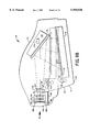
- FIG. 7 is front exterior view of the camera of FIG. 5 in the inoperative mode
- FIG. 8 is a front exterior view of the camera of FIG. 5 in the operative mode
- FIG. 9A is a schematical cross-sectional view of an embodiment of an optical system for the camera of FIG. 5 in a telephoto or long focal length mode;
- FIG. 9B is a schematical cross-sectional view of the embodiment of the optical system of FIG. 9A in a wide angle or short focal length mode;
- FIG. 9C is a schematical cross-sectional view of yet another embodiment of an optical system for the camera of FIG. 5 in a telephoto or long focal length mode;
- FIG. 9D is a schematical cross-sectional view of the embodiment of the optical system of FIG. 9C in a wide angle or short focal length mode;
- FIG. lOA is an operational drawing of a lens movement mechanism in the long focal length position, as shown in the multiple focal length camera of FIG. 9A, according to the principles of the invention
- FIG. lOB is an operational drawing of the lens movement mechanism of FIG. lOA in the short focal length position, as shown in the multiple focal length camera of FIG. 9B, according to the principles of the invention;
- FIG. 11 is an operational drawing of a lens movement mechanism for a multiple focal length camera in the long focal length position according to the principles of the invention
- FIG. 12 is an operational drawing of the lens movement mechanism of FIG. 11 for a multiple focal length camera in the short focal length position according to the principles of the invention
- FIGS. 13A and 13B are diagrams showing a front view of a mechanism for moving a first lens in and out of the optical path of a multiple focal length camera while concurrently moving a second lens in and out of the optical path of the viewfinder according to the principles of the invention;
- FIG. 13A illustrates the long focal length position where the first lens is positioned along the optical path of the camera and the second lens is positioned outside the optical path of the viewfinder;
- FIG. 13B illustrates the short focal length position where the first lens is positioned outside the optical path of the camera and the second lens is positioned along the optical path of the viewfinder.
- FIG. 1 illustrates an improved camera made according to the principles of the present invention.
- the camera 10 is preferably of the self-developing type and includes a housing assembly 12.
- the housing assembly 12 defines a lighttight compartment 14 for exposing and developing film units 16 of the self-developing type.
- the film units are stacked in a film cassette 18 such as described in U.S. Pat. No. 4,685, 791; which description is incorporated herein by reference and made a part hereof.
- the film units in the cassette 18 are sequentially exposed at a focal plane and developed in a known manner such as is described in U.S. Pat. No. 4,668,062; which description is also incorporated herein by reference and made a part hereof.
- a film cassette 18 such as described in U.S. Pat. No. 4,685, 791; which description is incorporated herein by reference and made a part hereof.
- the film units in the cassette 18 are sequentially exposed at a focal plane and developed in a known manner such as is described in U
- the camera 10 provides a film processing system, schematically represented by a pair of spread rollers 20 that are situated in the housing intermediate a cassette film exit slot (not shown) and a film exit slot (not shown).
- the spread rollers 20 when actuated serve to progressively spread the processing fluid located in a rupturable processing pod formed in each film unit. Following an exposure of the topmost film unit in the cassette, the latter is advanced through an exit slot (not shown) in the cassette by a film advancing mechanism, not shown but forming a part of the camera noted above, into a nip of the pair of the spread rollers 20.
- the spread rollers 20 rupture the pod and spread the processing fluid as they drive film unit from the film exit slot formed in a front wall of the camera housing.
- the camera includes a lens and shutter package assembly 30.
- the camera 10 includes a rangefinder system (not shown) to determine the distance to the subject to be photographed, a photocell (not shown), a viewfinder system 22 through which the scenes to be photographed maybe framed and a strobe 24 for illuminating the scene to be photographed.
- a mirror 26 for redirecting the image forming light rays traveling from the scene and a focusing lens system 28 of the lens and shutter package arrangement 30.
- An electronics module 29 is located behind the mirror 26 and serves to control the operations of the camera 10.
- a lens and shutter package arrangement 30 is provided for directing and focusing the image forming scene rays onto the focal plane. A more specific description of the lens and shutter package arrangement 30 used in this embodiment is described in U.S. Pat. No.
- the telephoto lens system 34 that cooperates with the existing focusing lens of the lens and shutter package 30.
- the telephoto lens system 34 of this embodiment includes a net positive lens doublet group 36 and appropriately spaced therefrom is a net negative doublet group 38. It will be seen that this telephoto lens arrangement has the shutter lens package 30 intermediate the positive and negative lens groups 36, 38.
- the lens groups 36, 38 can be made of a plurality of different and suitable materials and in this embodiment they are made of plastic materials.
- the telephoto lens system 34 can be have a variety of optical parameters and in this embodiment it can have a effective focal length of about 9 inches or 229 mm., a distortion of about +/-0.04 and a working f-number of about 17.5.
- both groups of the telephoto lens system 34 are preferably mounted on a rotatable lens carrier 40 for rotation about the axis 39 between an operative position such as illustrated in FIG. 1 and the dotted line position; whereby they are in a non-operative mode.
- the carrier 40 can be mounted for rotation manually or by a suitable motor driven system (not shown).
- a relatively shorter focal length positive lens 44 that will provide for a different focal length for the camera 10 when it optically cooperates with the focusing lens of the lens and shutter package 30.
- Such optical cooperation results when the second lens carrier 42 is in its operative position; such as shown by the dotted lines in FIG. 1.
- the second lens carrier 42 is rotatable about a second axis 45 between the noted operative position and an inoperative position. When the second carrier is in the inoperative position, the first lens carrier is in its operative position.
- the positive lens 44 is a single meniscus made from plastic.
- the lens 44 can have an effective focal length of about 4.79 inches or about 121.7 mm.; the distortion can be about +/-0.04 and a working f-number of 12.
- the lens 44 can have an aspherical surface 44a. These values are given since they are effective with a focusing lens of the type described in the lens and shutter package 30. Other optical values for different situations are contemplated.
- lens carriers 40 and 42 are desirable but by no means necessary to have movement of the lens carriers 40 and 42 tied to each other by for example a conventional pin/slot arrangement; whereby both lens carriers move in synchronism with each other, such that when the lens carrier 40 is in its operative position the second lens carrier 42 is in its inoperative position and vice versa.
- the present invention envisions that movement of the lens carriers can be achieved in response to manual effort, such as a handle (not shown) on the outside of the camera housing or through motor driven means.
- a handle not shown
- the present invention can provide for several focal lengths being selectively used.
- a viewfinder mask (not shown) be automatically actuated to move into the viewfinder so that the field of view corresponds to the particular focal length which is operative.
- a viewfinder mask can be selectively used, it will be appreciated that the viewfinder can have optical markings which will delineate the field of view associated with each focal length selected or lenses may be moved or exchanged to alter the viewfinder magnification, or a single reflex lens arrangement might be used.
- a Fresnel (not shown) can be selectively placed over the strobe so as to appropriately narrow or widen the field depending on which focal length system is being used.
- a switch member can be attached to either one or both of the respective lens carriers so that when they are moved into their respective operative positions, the microprocessor of the electronics system will compensate for the appropriate f-number of the lens system which is being used.
- the present invention envisions the use of other lens groups.
- the arrangement of the negative lens and positive lens groups can be reversed.
- the negative lens can be on the outside and the positive lens group would be on the inside so as to provide a reverse telephoto or retrofocus lens system.
- the telephoto lens group need not have the lens and shutter package arranged as illustrated but the telephoto lens group can be spaced in front of or disposed behind the package 30.
- FIG. 2 for illustrating another preferred embodiment of the present invention wherein a different lens carrier 46 is used in the same type of camera.
- the lens carrier 46 which carries both sets or groups of the different focal length lens groups is adapted to translate vertically, as seen by the arrows, between two distinct positions within the camera housing.
- a telephoto lens system 48 having the spaced positive and negative lens groups 50 and 52; respectively, and a lens 54 for providing a relatively shorter focal length than the other system.
- the lens carrier 46 has the telephoto lens system 48 in its operative position with respect to the lens and shutter package 30.
- a viewfinder mask 56 which is also carried the carrier 46 is in an operative relationship with the viewfinder 58 so as to delineate the field of view of the particular lens system in operative relationship with the focusing lens of the lens and shutter package 30. It will be appreciated that the mask 56 is laterally offset from the lenses on the lens carrier since it will cooperate with the viewfinder.
- the lens carrier When it is desired to translate the lens system 48 to its inoperative position, the lens carrier is moved downwardly so as to present the lens 54 in its operative position (not shown). During such movement, the mask 56 moves out of operative relationship to the viewfinder 58. Movement of the lens carrier 46 can be effected in any suitable manner, such as manually or through a suitable drive system.
- FIGS. 5-8 show another embodiment of an improved camera made according to the principles of the present invention.
- the camera 10 is preferably of the self-developing type and includes a first (upper) housing 112 and a second (lower) housing 114 which are operably joined together for movement relative to one another about a pivot 116.
- the housings are movable between a first (closed) position shown in FIG. 5, where the second housing 114 is at least partially received within the first housing 112, and a second (open) position shown in FIG. 6 where the second housing 114 is moved at least partially away from the first housing 112.
- Moving the first and second housings to the first position places the camera in an inoperable mode whereby the camera is unable to take an image of a scene.
- moving the first and second housings into the second position places the camera 110 in an operable mode ready for taking an image of a scene.
- the opening and closing of the folding camera 110 can be accomplished by methods and devices well known in the art.
- U.S. Pat. No. 4,508,440 issued Apr. 2, 1985 to Costa et al. discloses an erecting assembly, which description is herein incorporated by reference, for opening and closing a folding camera.
- the camera described in Costa uses a push button type of pad for activating the erection system, whereas the camera 110 can alternatively use a slide switch 195, shown in FIGS. 5 and 6, as the means for activating the erection system.
- the opening and closing of the camera could be operated by a motor (not shown).
- FIG. 8 shows a slot 121 included in a front wall 125 of the second housing 114, where an exposed film unit can exit the camera 110.
- the slot 121 in the first position the slot 121 is at least partially or perhaps fully disposed within the first housing 112 so that the exposed film unit cannot exit the camera 110 through the slot 121, whereas, in the second position the slot 121 (as shown in FIG. 8) is fully exposed below the first housing 112 so that the exposed film unit can exit the camera 110 through the slot 121.
- the functional advantages of the above described features of the invention include camera compactness, security against mistakenly taking a picture when the housings are in the first position (i.e. the camera is in the inoperative mode), and further protection from unwanted leaking of light into the camera through the slot 121 when the camera is inoperative and the housings are in the first, closed position.
- FIGS. 9A and 9B Another preferred embodiment of an imaging device made according to the principles of the present invention is a folding multiple focal length self-developing type camera as shown in the left cross-sectional schematical views of FIGS. 9A and 9B.
- This particular embodiment extends the camera 110 of FIGS. 5-8 to multiple focal lengths.
- the first and second housings 112 and 114 together define a light-tight compartment for exposing and developing a self-developing type film unit 116 (i.e. an image recordable unit).
- a plurality of the film units 116 are stacked in a film cassette 118 and are sequentially exposed at a focal plane 117 and developed in a known manner as previously described.
- the camera 110 provides a film processing system, schematically represented by a pair of spread rollers 120 that are situated in the second housing 114 near a cassette film exit slot 111 and a camera film exit slot 121.
- the spread rollers 120 when actuated serve to progressively spread a processing fluid located in a rupturable processing pod (not shown) in each film unit 116.
- the film unit 116 is advanced through the cassette film exit slot 111 by a film advancing mechanism (not shown but forming a part of the camera 110) into a nip 123 of the pair of spread rollers 120.
- the spread rollers 120 rupture the pod and spread the processing fluid as they drive the film unit 116 from the camera film exit slot 121 formed in a front wall 125 of the second housing 114.
- the camera 110 includes an assembly 130 which, in turn, houses a shutter (not shown) and a focusing lens configuration such as the pair of quintic lens 133 and 135 shown and well known in the art. Basically, one quintic lens 135 is fixed and the other quintic lens 133 is movable throughout different focusing powers to properly focus the light from a scene in accordance with the selected focal length of the camera.
- the shutter is opened and closed to allow a predetermined amount of light 162 into the camera 110 to expose the film unit 116 along the focal plane 117.
- FIG. 9A illustrates the folding multiple focal length camera 110 with a telephoto lens having a selected long focal length positioned in the optical path 162 whereas, FIG. 9B illustrates the same camera 110 with a wide angle lens pair having a selected short focal length positioned in the optical path 162.
- the camera 110 also includes a ranging system for determining the distance between the camera and the subject to be photographed.
- the preferred camera includes an ultrasonic transducer 160 as shown in FIG. 8. Since the ultrasonic ranging system is not a part of the present invention, it will not be described here in detail. An example of such a system is disclosed in U.S. Pat. No. 4,199,246 issued Apr. 22, 1980 to Muggli which is herein incorporated by reference in its entirety for background information.
- an ultrasonic transducer transmits a relatively short burst of ultrasonic frequencies and a synchronized receiver processes an echo signal produced by the transducer upon receipt of the echo after a predetermined time. This receiver produces a ranging signal having a characteristic related to the distance of the nearest subject being photographed.
- a lens element of a variable focus lens system is moved to the appropriate focal position corresponding to the subject range.
- the camera 110 also includes a photometric device such as a photocell 122 for light measurement, a viewfinder system or optics 164 through which the scene to be photographed may be framed, and a strobe 124 for illuminating the scene to be photographed.
- a mirror 126 is used to redirect the image forming light rays 162 received from the scene.
- An electronics module or controller 129 is located behind the mirror 126 and serves to control the operations of the camera 110. Settings relating to the proper operation of the camera are stored in a digital memory such as a look-up table 226 located within the controller 129.
- the lens and shutter assembly 130 of the camera 110 contains the shutter and the quintic focusing lenses 133 and 135 which together direct and focus the image forming light rays 162 onto the film unit 116 along the focal plane 117.
- the shutter blades (not shown) are located between quintic lenses 133 and 135.
- the shutter blades open and close under the guidance of the controller 129 to allow the proper, predetermined amount of light 162 to expose the film unit 116.
- the controller 129 obtains predetermined exposure control values from the look-up table 226 for controlling the shutter operation corresponding to the amount of light 162 needed to properly expose the film unit 116 whereby the amount of light 162 is measured by the photocell 122 and read by the controller 129.
- the movable quintic lens 133 is movable throughout a number of zones or positions, either manually or automatically, to adjust the focus of the camera in cooperation with the fixed quintic lens 135.
- the range finding system determines the distance between the camera and the subject, then the controller 129 uses that information to set the quintic lenses into the appropriate zone again, retrieving predetermined information from the look-up table 226.
- the assembly 130 is embellished in FIG. 9A to include a transparent dust protector plate 132 covering the lens and shutter assembly 130 given the fact that there are provided mechanisms for providing multiple focal lengths in the camera 110.
- FIGS. 9C and 9D Another embodiment of a folding multiple focal length camera made according to the principles of the present invention is shown in FIGS. 9C and 9D.
- the only difference from the embodiment illustrated in FIGS. 9A and 9B is the fact that the lens cradle or second housing 140 is installed so that the lens not in use on the second housing 140 is positioned above the optical path of the camera (rather than below the optical path of the camera of FIGS. 9A and 9B). This feature allows the camera 110 to be more easily and compactly folded.
- the folding camera 110 is illustrated both in the erect or open position as designated by solid lines, and in the folded or closed position as designated by lines of dots and dashes.
- FIGS. 1OA and 1OB illustrate a lens movement mechanism 210, made in accordance with the principles of the present invention, for use in the multiple focal length cameras of FIGS. 9A through 9D.
- the lens movement mechanism or lens positioning system 210 is provided to allow adjustment to the focus, viewfinder, and photometric optics when different focal lengths are selected.
- FIG. 10A shows the mechanism or apparatus 210 in a telephoto (i.e. long focal length) position
- Figure 10B shows the apparatus 210 in a wide angle (i.e. short focal length) position.
- Other focal lengths could be used.
- a first housing 180 moves left or right linearly along its longitudinal axis 187 which, in turn, causes the second housing or lens cradle 140 to rotate about an axis formed by the shafts 84A and 84B.
- the linear motion of the first housing is transferred by an integrally molded rack 199 to a gear or pinion 196 which is attached adjacent to one end of a gear shaft 186 and which rotates the shaft 186 about its longitudinal axis 141 which, in turn, rotates a fork arm 188 attached adjacent to the other end of the shaft 186.
- the rotation of the fork arm 188 causes rotation of the extending arm 190 connected therewith which then rotates the shafts 84A and 84B causing the second housing 140 to rotate as well.
- the shafts 84A and 84B are both fixedly attached to the second housing 140 and both rotate about the same longitudinal axis or second housing means axis 139.
- the linear movement of the first housing 180 can be initiated manually, for instance, by an user 206 moving a slide switch 198 into one of two positions whereby locking mechanisms (not shown) are used to lock the first and second housings 180 and 140, respectively, into the predetermined positions shown in FIGS. 10A and 10B.
- the long focal length or telephoto position of FIG. 10A also FIGS.
- FIGS. 9A and 9C is established when a first focusing lens means or lens 200 lines up with a second focusing lens means or positive lens 143, and both a photometer 122 and viewfinder optics means or viewfinder optics 164 line up with means for passing light or opening 202.
- the short focal length or wide angle position of Figure 10B (also FIGS. 9B and 9D) is established when the negative wide angle lens, i.e. the second focusing lens means, 144 lines up with the opening 202, the photometer 122 lines up with photometric correction means or a correction photometer 192 and the viewfinder optics 164 lines up with the corrective viewfinder optics or viewfinder optics correction means 194.
- FIGS. 11 and 12 illustrate a second lens movement mechanism 280, made in accordance with the principles of the present invention, which could be used in place of the lens movement mechanisms shown in the multiple focal length cameras of FIGS. 9A through 9D.
- the lens movement mechanism or lens positioning system 280 is provided to allow adjustment to the focus, viewfinder, and photometric optics when different focal lengths are selected.
- FIG. 11 shows the mechanism or apparatus 280 in a telephoto (i.e. long focal length) position
- FIG. 12 shows the apparatus 280 in a wide angle (i.e. short focal length) position. Other focal lengths could be used.
- a first housing 180 moves left or right linearly along its longitudinal axis 187 which, in turn, causes the shafts 228, 234 to rotate the second housing, i.e. lens cradles 220, 222, about axes 240, 238 respectively.
- the linear motion of the first housing is transferred by an integrally molded rack 199 to a gear or pinion 196 which is attached adjacent to one end of a gear shaft 186 and which rotates the shaft 186 about its longitudinal axis 141 which, in turn, rotates beveled gears 224 and 226.
- the gear 226 is attached to and rotates a first lens shaft 228 which, in turn, rotates a first lens carrier or first lens holder 220 along axis 240.
- the rotary motion of the first lens shaft 228 is also applied to a second lens shaft 234 through pivotally connected links, i.e. linkage, 230, 232 and 236, causing a second lens holder 222 to rotate about axis 238.
- Link 230 is fixedly attached to the first lens shaft 228 so that any rotation of the first lens shaft 228 will cause an equal angular rotation of link 228 about axis 240.
- link 236 is fixedly attached to the second lens shaft 234 so that any rotation of link 236 will cause an equal angular rotation of the second shaft 234.
- the linkage 230, 232 and 236 facilitates the transfer of rotational movement of the first lens shaft 228 to rotational movement of the second lens shaft 234.
- the linear movement of the first housing 180 can be initiated manually, for instance, by an user moving a slide switch 198 into one of two positions whereby locking mechanisms (not shown) are used to lock the first and second housings 180 and 222, 220, respectively, into the predetermined positions shown in FIGS. 11 and 12.
- the long focal length or telephoto position of FIG. 11 is established when a first focusing lens means or lens 200 and a second focusing lens means or positive lens 143 are both positioned along the imaging optical path 162 of the camera.
- the means for passing light or opening 202 lines up with both the photometer optical path 197 of the photometer 122 and the viewfinder optical path 195 of the viewfinder optics 164.
- the short focal length or wide angle position of FIG. 12 is established when the second focusing lens means, i.e. the negative wide angle lens, 144 is positioned along the imaging optical path 162 through the opening 202.
- the photometric correction means or a correction photometer 192 and the photometer 122 are both positioned along the photometer optical path 197.
- the viewfinder optics 164 and the corrective viewfinder optics or viewfinder optics correction means 194 are both positioned along the viewfinder optical path 195.
- FIGS. 13A and 13B are diagrams showing a front view of a mechanism 280 for moving a first lens 264 in and out of the imaging optical path 270 of a multiple focal length camera (not shown) while concurrently moving a second lens 260 in and out of the optical path 272 of the viewfinder (not shown).
- FIG. 13A illustrates the long focal length position where the first lens 264 is positioned along the imaging optical path 270 and the second lens 260 is positioned outside the viewfinder optical path 272.
- FIG. 13B illustrates the short focal length position where the first lens 264 is positioned outside the imaging optical path 270 and the second lens 260 is positioned along the viewfinder optical path 272.
- the mechanism 280 includes a body 250 having a pivot point 252, a stop 254, an opening 266, and a slot for allowing the second lens 260 to move between first and second positions.
- the movement of the first lens 264 perpendicular to the optical camera axis 270 can be facilitated by any known means, such as the rack and pinion mechanism previously described and illustrated in FIGS. 11 and 12.
- a leaf spring 258 is fixedly connected at one end to the first lens 264 and at the other end to a first arm 256.
- the first arm 256 is pivotally connected at one end to the body 250 at pivot point 252 and fixedly connected at the other end to the second lens 260.
- the second lens 260 includes a second arm 262 fixedly attached thereto.
- the leaf spring 258 and first arm 256 hold the second lens 260 in the position shown outside of the viewfinder optical path 272.
- the leaf spring 258 and the first arm 256 move and hold the second lens 260 into alignment with the viewfinder optical path 272. The accuracy of stopping the second lens 260 in the correct position along the viewfinder optical path 272 is assured by the second arm 262 coming into contact with stop 254.
- first and second housings could be a camera back attachable suitably to a photographic apparatus.
Landscapes
- Physics & Mathematics (AREA)
- General Physics & Mathematics (AREA)
- Structure And Mechanism Of Cameras (AREA)
Abstract
Description
Claims (28)
Priority Applications (1)
| Application Number | Priority Date | Filing Date | Title |
|---|---|---|---|
| US09/008,644 US5950020A (en) | 1997-01-22 | 1998-01-16 | Folding photographic method and apparatus |
Applications Claiming Priority (2)
| Application Number | Priority Date | Filing Date | Title |
|---|---|---|---|
| US3764997P | 1997-01-22 | 1997-01-22 | |
| US09/008,644 US5950020A (en) | 1997-01-22 | 1998-01-16 | Folding photographic method and apparatus |
Publications (1)
| Publication Number | Publication Date |
|---|---|
| US5950020A true US5950020A (en) | 1999-09-07 |
Family
ID=26678408
Family Applications (1)
| Application Number | Title | Priority Date | Filing Date |
|---|---|---|---|
| US09/008,644 Expired - Fee Related US5950020A (en) | 1997-01-22 | 1998-01-16 | Folding photographic method and apparatus |
Country Status (1)
| Country | Link |
|---|---|
| US (1) | US5950020A (en) |
Cited By (4)
| Publication number | Priority date | Publication date | Assignee | Title |
|---|---|---|---|---|
| US6175691B1 (en) * | 1999-02-11 | 2001-01-16 | Polaroid Corporation | Multiple mode imaging system |
| US20040116166A1 (en) * | 2002-12-13 | 2004-06-17 | Fuji Photo Film Co., Ltd. | Portable terminal with camera |
| CN100394340C (en) * | 2003-12-23 | 2008-06-11 | 三星电子株式会社 | Method and device for acquiring rotational motion |
| CN110441311A (en) * | 2019-07-22 | 2019-11-12 | 中国科学院上海光学精密机械研究所 | The multifocal camera lens of multiaxis for the imaging of more object planes |
Citations (7)
| Publication number | Priority date | Publication date | Assignee | Title |
|---|---|---|---|---|
| US4199246A (en) * | 1976-10-04 | 1980-04-22 | Polaroid Corporation | Ultrasonic ranging system for a camera |
| US4291965A (en) * | 1980-10-06 | 1981-09-29 | Polaroid Corporation | Apparatus for automatically selecting a preselected focal position for a lens system |
| US4452519A (en) * | 1982-12-16 | 1984-06-05 | Polaroid Corporation | Folding camera having erectable light source |
| US4650292A (en) * | 1983-12-28 | 1987-03-17 | Polaroid Corporation | Analytic function optical component |
| US4655571A (en) * | 1984-07-27 | 1987-04-07 | Fuji Photo Film Co., Ltd. | Telephoto lens camera |
| US4668062A (en) * | 1985-03-04 | 1987-05-26 | Polaroid Corporation | Apparatus for precluding rotational movement of an advancing film unit |
| US4685791A (en) * | 1986-01-21 | 1987-08-11 | Polaroid Corporation | Film cassette |
-
1998
- 1998-01-16 US US09/008,644 patent/US5950020A/en not_active Expired - Fee Related
Patent Citations (7)
| Publication number | Priority date | Publication date | Assignee | Title |
|---|---|---|---|---|
| US4199246A (en) * | 1976-10-04 | 1980-04-22 | Polaroid Corporation | Ultrasonic ranging system for a camera |
| US4291965A (en) * | 1980-10-06 | 1981-09-29 | Polaroid Corporation | Apparatus for automatically selecting a preselected focal position for a lens system |
| US4452519A (en) * | 1982-12-16 | 1984-06-05 | Polaroid Corporation | Folding camera having erectable light source |
| US4650292A (en) * | 1983-12-28 | 1987-03-17 | Polaroid Corporation | Analytic function optical component |
| US4655571A (en) * | 1984-07-27 | 1987-04-07 | Fuji Photo Film Co., Ltd. | Telephoto lens camera |
| US4668062A (en) * | 1985-03-04 | 1987-05-26 | Polaroid Corporation | Apparatus for precluding rotational movement of an advancing film unit |
| US4685791A (en) * | 1986-01-21 | 1987-08-11 | Polaroid Corporation | Film cassette |
Cited By (6)
| Publication number | Priority date | Publication date | Assignee | Title |
|---|---|---|---|---|
| US6175691B1 (en) * | 1999-02-11 | 2001-01-16 | Polaroid Corporation | Multiple mode imaging system |
| US20040116166A1 (en) * | 2002-12-13 | 2004-06-17 | Fuji Photo Film Co., Ltd. | Portable terminal with camera |
| US7599722B2 (en) * | 2002-12-13 | 2009-10-06 | Fujifilm Corporation | Mobile camera phone with adjustable focal length |
| CN100394340C (en) * | 2003-12-23 | 2008-06-11 | 三星电子株式会社 | Method and device for acquiring rotational motion |
| CN110441311A (en) * | 2019-07-22 | 2019-11-12 | 中国科学院上海光学精密机械研究所 | The multifocal camera lens of multiaxis for the imaging of more object planes |
| CN110441311B (en) * | 2019-07-22 | 2021-10-08 | 中国科学院上海光学精密机械研究所 | Multi-axis multifocal lens for multi-object imaging |
Similar Documents
| Publication | Publication Date | Title |
|---|---|---|
| US4114171A (en) | Reflex camera with internal zoom lens | |
| EP0206256B1 (en) | Exposure control for pseudo telephoto camera | |
| JPH0531130B2 (en) | ||
| US5721995A (en) | Lens-fitted photographic film unit having shutter with connection lever and crank lever | |
| EP0083178B1 (en) | Folding camera | |
| US4392732A (en) | Folding camera with viewfinder having independently mounted optical elements | |
| US5950020A (en) | Folding photographic method and apparatus | |
| US4387978A (en) | Folding camera with pivotally mounted viewfinder | |
| US4284337A (en) | Photographic apparatus | |
| US5628037A (en) | Parallax correcting mechanism for real image type viewfinders | |
| US3792649A (en) | Automatic return mechanism for an exposure trim assembly | |
| US5457511A (en) | Single-lens reflex camera | |
| US6055374A (en) | Folding camera | |
| JP3313948B2 (en) | Focus detection device and camera | |
| JP2000089275A (en) | Camera | |
| JP3215761B2 (en) | Film unit with lens | |
| JP2000089082A (en) | Camera | |
| JP3236734B2 (en) | Diopter correction device for back-drive AF single-lens reflex camera | |
| JP3165303B2 (en) | Camera exposure screen switching device | |
| JP3179919B2 (en) | Optical path switching mechanism | |
| JP2000089276A (en) | Lens moving device | |
| JP3335452B2 (en) | Portable camera | |
| EP0854381A1 (en) | Camera having a through-the-lens finder | |
| JPH07159937A (en) | Device for switching visual field range | |
| JPH04273207A (en) | Optical equipment with collapsible zoom lens |
Legal Events
| Date | Code | Title | Description |
|---|---|---|---|
| AS | Assignment |
Owner name: POLAROID CORPORATION, MASSACHUSETTS Free format text: ASSIGNMENT OF ASSIGNORS INTEREST;ASSIGNORS:BALL, ALAN D.;CLARK, PETER P.;KIRBY, JOHN P.;AND OTHERS;REEL/FRAME:009199/0826;SIGNING DATES FROM 19980428 TO 19980514 |
|
| AS | Assignment |
Owner name: MORGAN GUARANTY TRUST COMPANY OF NEW YORK, NEW YOR Free format text: SECURITY AGREEMENT;ASSIGNOR:POLAROID CORPORATION;REEL/FRAME:011658/0699 Effective date: 20010321 |
|
| FPAY | Fee payment |
Year of fee payment: 4 |
|
| AS | Assignment |
Owner name: OEP IMAGINIG OPERATING CORPORATION, NEW YORK Free format text: ASSIGNMENT OF ASSIGNORS INTEREST;ASSIGNOR:POLAROID CORPORATION;REEL/FRAME:016427/0144 Effective date: 20020731 Owner name: POLAROID CORPORATION, NEW YORK Free format text: CHANGE OF NAME;ASSIGNOR:OEP IMAGING OPERATING CORPORATION;REEL/FRAME:016470/0006 Effective date: 20020801 Owner name: OEP IMAGINIG OPERATING CORPORATION,NEW YORK Free format text: ASSIGNMENT OF ASSIGNORS INTEREST;ASSIGNOR:POLAROID CORPORATION;REEL/FRAME:016427/0144 Effective date: 20020731 Owner name: POLAROID CORPORATION,NEW YORK Free format text: CHANGE OF NAME;ASSIGNOR:OEP IMAGING OPERATING CORPORATION;REEL/FRAME:016470/0006 Effective date: 20020801 |
|
| AS | Assignment |
Owner name: WILMINGTON TRUST COMPANY, AS COLLATERAL AGENT, DEL Free format text: ASSIGNMENT OF ASSIGNORS INTEREST;ASSIGNORS:POLAROLD HOLDING COMPANY;POLAROID CORPORATION;POLAROID ASIA PACIFIC LLC;AND OTHERS;REEL/FRAME:016602/0332 Effective date: 20050428 Owner name: JPMORGAN CHASE BANK,N.A,AS ADMINISTRATIVE AGENT, W Free format text: SECURITY INTEREST;ASSIGNORS:POLAROID HOLDING COMPANY;POLAROID CORPORATION;POLAROID ASIA PACIFIC LLC;AND OTHERS;REEL/FRAME:016602/0603 Effective date: 20050428 Owner name: WILMINGTON TRUST COMPANY, AS COLLATERAL AGENT,DELA Free format text: SECURITY AGREEMENT;ASSIGNORS:POLAROLD HOLDING COMPANY;POLAROID CORPORATION;POLAROID ASIA PACIFIC LLC;AND OTHERS;REEL/FRAME:016602/0332 Effective date: 20050428 Owner name: JPMORGAN CHASE BANK,N.A,AS ADMINISTRATIVE AGENT,WI Free format text: SECURITY INTEREST;ASSIGNORS:POLAROID HOLDING COMPANY;POLAROID CORPORATION;POLAROID ASIA PACIFIC LLC;AND OTHERS;REEL/FRAME:016602/0603 Effective date: 20050428 Owner name: WILMINGTON TRUST COMPANY, AS COLLATERAL AGENT, DEL Free format text: SECURITY AGREEMENT;ASSIGNORS:POLAROLD HOLDING COMPANY;POLAROID CORPORATION;POLAROID ASIA PACIFIC LLC;AND OTHERS;REEL/FRAME:016602/0332 Effective date: 20050428 |
|
| AS | Assignment |
Owner name: POLAROID CORPORATION (F/K/A OEP IMAGING OPERATING Free format text: U.S. BANKRUPTCY COURT DISTRICT OF DELAWARE ORDER AUTHORIZING RELEASE OF ALL LIENS;ASSIGNOR:JPMORGAN CHASE BANK, N.A. (F/K/A MORGAN GUARANTY TRUST COMPANY OF NEW YORK);REEL/FRAME:016621/0377 Effective date: 20020418 Owner name: POLAROID CORPORATION (F/K/A OEP IMAGING OPERATING COMPANY), MASSACHUSETTS Free format text: U.S. BANKRUPTCY COURT DISTRICT OF DELAWARE ORDER AUTHORIZING RELEASE OF ALL LIENS;ASSIGNOR:JPMORGAN CHASE BANK, N.A. (F/K/A MORGAN GUARANTY TRUST COMPANY OF NEW YORK);REEL/FRAME:016621/0377 Effective date: 20020418 |
|
| AS | Assignment |
Owner name: OEP IMAGING OPERATING CORPORATION,NEW YORK Free format text: ASSIGNMENT OF ASSIGNORS INTEREST;ASSIGNOR:POLAROID CORPORATION;REEL/FRAME:018584/0600 Effective date: 20020731 Owner name: OEP IMAGING OPERATING CORPORATION, NEW YORK Free format text: ASSIGNMENT OF ASSIGNORS INTEREST;ASSIGNOR:POLAROID CORPORATION;REEL/FRAME:018584/0600 Effective date: 20020731 |
|
| AS | Assignment |
Owner name: POLAROID CORPORATION (FMR OEP IMAGING OPERATING CO Free format text: SUPPLEMENTAL ASSIGNMENT OF PATENTS;ASSIGNOR:PRIMARY PDC, INC. (FMR POLAROID CORPORATION);REEL/FRAME:019077/0001 Effective date: 20070122 Owner name: POLAROID CORPORATION (FMR OEP IMAGING OPERATING CORP.), MASSACHUSETTS Free format text: SUPPLEMENTAL ASSIGNMENT OF PATENTS;ASSIGNOR:PRIMARY PDC, INC. (FMR POLAROID CORPORATION);REEL/FRAME:019077/0001 Effective date: 20070122 |
|
| REMI | Maintenance fee reminder mailed | ||
| FPAY | Fee payment |
Year of fee payment: 8 |
|
| SULP | Surcharge for late payment |
Year of fee payment: 7 |
|
| AS | Assignment |
Owner name: POLAROID HOLDING COMPANY, MASSACHUSETTS Free format text: RELEASE OF SECURITY INTEREST IN PATENTS;ASSIGNOR:WILMINGTON TRUST COMPANY;REEL/FRAME:019699/0512 Effective date: 20070425 Owner name: POLAROID CORPORATION, MASSACHUSETTS Free format text: RELEASE OF SECURITY INTEREST IN PATENTS;ASSIGNOR:WILMINGTON TRUST COMPANY;REEL/FRAME:019699/0512 Effective date: 20070425 Owner name: POLAROID CAPITAL LLC, MASSACHUSETTS Free format text: RELEASE OF SECURITY INTEREST IN PATENTS;ASSIGNOR:WILMINGTON TRUST COMPANY;REEL/FRAME:019699/0512 Effective date: 20070425 Owner name: POLAROID ASIA PACIFIC LLC, MASSACHUSETTS Free format text: RELEASE OF SECURITY INTEREST IN PATENTS;ASSIGNOR:WILMINGTON TRUST COMPANY;REEL/FRAME:019699/0512 Effective date: 20070425 Owner name: POLAROID EYEWEAR LLC, MASSACHUSETTS Free format text: RELEASE OF SECURITY INTEREST IN PATENTS;ASSIGNOR:WILMINGTON TRUST COMPANY;REEL/FRAME:019699/0512 Effective date: 20070425 Owner name: POLOROID INTERNATIONAL HOLDING LLC, MASSACHUSETTS Free format text: RELEASE OF SECURITY INTEREST IN PATENTS;ASSIGNOR:WILMINGTON TRUST COMPANY;REEL/FRAME:019699/0512 Effective date: 20070425 Owner name: POLAROID INVESTMENT LLC, MASSACHUSETTS Free format text: RELEASE OF SECURITY INTEREST IN PATENTS;ASSIGNOR:WILMINGTON TRUST COMPANY;REEL/FRAME:019699/0512 Effective date: 20070425 Owner name: POLAROID LATIN AMERICA I CORPORATION, MASSACHUSETT Free format text: RELEASE OF SECURITY INTEREST IN PATENTS;ASSIGNOR:WILMINGTON TRUST COMPANY;REEL/FRAME:019699/0512 Effective date: 20070425 Owner name: POLAROID NEW BEDFORD REAL ESTATE LLC, MASSACHUSETT Free format text: RELEASE OF SECURITY INTEREST IN PATENTS;ASSIGNOR:WILMINGTON TRUST COMPANY;REEL/FRAME:019699/0512 Effective date: 20070425 Owner name: POLAROID NORWOOD REAL ESTATE LLC, MASSACHUSETTS Free format text: RELEASE OF SECURITY INTEREST IN PATENTS;ASSIGNOR:WILMINGTON TRUST COMPANY;REEL/FRAME:019699/0512 Effective date: 20070425 Owner name: POLAROID WALTHAM REAL ESTATE LLC, MASSACHUSETTS Free format text: RELEASE OF SECURITY INTEREST IN PATENTS;ASSIGNOR:WILMINGTON TRUST COMPANY;REEL/FRAME:019699/0512 Effective date: 20070425 Owner name: PETTERS CONSUMER BRANDS, LLC, MASSACHUSETTS Free format text: RELEASE OF SECURITY INTEREST IN PATENTS;ASSIGNOR:WILMINGTON TRUST COMPANY;REEL/FRAME:019699/0512 Effective date: 20070425 Owner name: PETTERS CONSUMER BRANDS INTERNATIONAL, LLC, MASSAC Free format text: RELEASE OF SECURITY INTEREST IN PATENTS;ASSIGNOR:WILMINGTON TRUST COMPANY;REEL/FRAME:019699/0512 Effective date: 20070425 Owner name: ZINK INCORPORATED, MASSACHUSETTS Free format text: RELEASE OF SECURITY INTEREST IN PATENTS;ASSIGNOR:WILMINGTON TRUST COMPANY;REEL/FRAME:019699/0512 Effective date: 20070425 Owner name: POLAROID HOLDING COMPANY,MASSACHUSETTS Free format text: RELEASE OF SECURITY INTEREST IN PATENTS;ASSIGNOR:WILMINGTON TRUST COMPANY;REEL/FRAME:019699/0512 Effective date: 20070425 Owner name: POLAROID CORPORATION,MASSACHUSETTS Free format text: RELEASE OF SECURITY INTEREST IN PATENTS;ASSIGNOR:WILMINGTON TRUST COMPANY;REEL/FRAME:019699/0512 Effective date: 20070425 Owner name: POLAROID CAPITAL LLC,MASSACHUSETTS Free format text: RELEASE OF SECURITY INTEREST IN PATENTS;ASSIGNOR:WILMINGTON TRUST COMPANY;REEL/FRAME:019699/0512 Effective date: 20070425 Owner name: POLAROID ASIA PACIFIC LLC,MASSACHUSETTS Free format text: RELEASE OF SECURITY INTEREST IN PATENTS;ASSIGNOR:WILMINGTON TRUST COMPANY;REEL/FRAME:019699/0512 Effective date: 20070425 Owner name: POLAROID EYEWEAR LLC,MASSACHUSETTS Free format text: RELEASE OF SECURITY INTEREST IN PATENTS;ASSIGNOR:WILMINGTON TRUST COMPANY;REEL/FRAME:019699/0512 Effective date: 20070425 Owner name: POLOROID INTERNATIONAL HOLDING LLC,MASSACHUSETTS Free format text: RELEASE OF SECURITY INTEREST IN PATENTS;ASSIGNOR:WILMINGTON TRUST COMPANY;REEL/FRAME:019699/0512 Effective date: 20070425 Owner name: POLAROID INVESTMENT LLC,MASSACHUSETTS Free format text: RELEASE OF SECURITY INTEREST IN PATENTS;ASSIGNOR:WILMINGTON TRUST COMPANY;REEL/FRAME:019699/0512 Effective date: 20070425 Owner name: POLAROID LATIN AMERICA I CORPORATION,MASSACHUSETTS Free format text: RELEASE OF SECURITY INTEREST IN PATENTS;ASSIGNOR:WILMINGTON TRUST COMPANY;REEL/FRAME:019699/0512 Effective date: 20070425 Owner name: POLAROID NEW BEDFORD REAL ESTATE LLC,MASSACHUSETTS Free format text: RELEASE OF SECURITY INTEREST IN PATENTS;ASSIGNOR:WILMINGTON TRUST COMPANY;REEL/FRAME:019699/0512 Effective date: 20070425 Owner name: POLAROID NORWOOD REAL ESTATE LLC,MASSACHUSETTS Free format text: RELEASE OF SECURITY INTEREST IN PATENTS;ASSIGNOR:WILMINGTON TRUST COMPANY;REEL/FRAME:019699/0512 Effective date: 20070425 Owner name: POLAROID WALTHAM REAL ESTATE LLC,MASSACHUSETTS Free format text: RELEASE OF SECURITY INTEREST IN PATENTS;ASSIGNOR:WILMINGTON TRUST COMPANY;REEL/FRAME:019699/0512 Effective date: 20070425 Owner name: PETTERS CONSUMER BRANDS, LLC,MASSACHUSETTS Free format text: RELEASE OF SECURITY INTEREST IN PATENTS;ASSIGNOR:WILMINGTON TRUST COMPANY;REEL/FRAME:019699/0512 Effective date: 20070425 Owner name: PETTERS CONSUMER BRANDS INTERNATIONAL, LLC,MASSACH Free format text: RELEASE OF SECURITY INTEREST IN PATENTS;ASSIGNOR:WILMINGTON TRUST COMPANY;REEL/FRAME:019699/0512 Effective date: 20070425 Owner name: ZINK INCORPORATED,MASSACHUSETTS Free format text: RELEASE OF SECURITY INTEREST IN PATENTS;ASSIGNOR:WILMINGTON TRUST COMPANY;REEL/FRAME:019699/0512 Effective date: 20070425 |
|
| AS | Assignment |
Owner name: POLAROID HOLDING COMPANY, MASSACHUSETTS Free format text: RELEASE OF SECURITY INTEREST IN PATENTS;ASSIGNOR:JPMORGAN CHASE BANK, N.A.;REEL/FRAME:020733/0001 Effective date: 20080225 Owner name: POLAROID INTERNATIONAL HOLDING LLC, MASSACHUSETTS Free format text: RELEASE OF SECURITY INTEREST IN PATENTS;ASSIGNOR:JPMORGAN CHASE BANK, N.A.;REEL/FRAME:020733/0001 Effective date: 20080225 Owner name: POLAROID INVESTMENT LLC, MASSACHUSETTS Free format text: RELEASE OF SECURITY INTEREST IN PATENTS;ASSIGNOR:JPMORGAN CHASE BANK, N.A.;REEL/FRAME:020733/0001 Effective date: 20080225 Owner name: POLAROID LATIN AMERICA I CORPORATION, MASSACHUSETT Free format text: RELEASE OF SECURITY INTEREST IN PATENTS;ASSIGNOR:JPMORGAN CHASE BANK, N.A.;REEL/FRAME:020733/0001 Effective date: 20080225 Owner name: POLAROID NEW BEDFORD REAL ESTATE LLC, MASSACHUSETT Free format text: RELEASE OF SECURITY INTEREST IN PATENTS;ASSIGNOR:JPMORGAN CHASE BANK, N.A.;REEL/FRAME:020733/0001 Effective date: 20080225 Owner name: POLAROID NORWOOD REAL ESTATE LLC, MASSACHUSETTS Free format text: RELEASE OF SECURITY INTEREST IN PATENTS;ASSIGNOR:JPMORGAN CHASE BANK, N.A.;REEL/FRAME:020733/0001 Effective date: 20080225 Owner name: POLAROID WALTHAM REAL ESTATE LLC, MASSACHUSETTS Free format text: RELEASE OF SECURITY INTEREST IN PATENTS;ASSIGNOR:JPMORGAN CHASE BANK, N.A.;REEL/FRAME:020733/0001 Effective date: 20080225 Owner name: POLAROID CONSUMER ELECTRONICS, LLC, (FORMERLY KNOW Free format text: RELEASE OF SECURITY INTEREST IN PATENTS;ASSIGNOR:JPMORGAN CHASE BANK, N.A.;REEL/FRAME:020733/0001 Effective date: 20080225 Owner name: POLAROID CONSUMER ELECTRONICS INTERNATIONAL, LLC, Free format text: RELEASE OF SECURITY INTEREST IN PATENTS;ASSIGNOR:JPMORGAN CHASE BANK, N.A.;REEL/FRAME:020733/0001 Effective date: 20080225 Owner name: ZINK INCORPORATED, MASSACHUSETTS Free format text: RELEASE OF SECURITY INTEREST IN PATENTS;ASSIGNOR:JPMORGAN CHASE BANK, N.A.;REEL/FRAME:020733/0001 Effective date: 20080225 Owner name: POLAROID CORPORATION, MASSACHUSETTS Free format text: RELEASE OF SECURITY INTEREST IN PATENTS;ASSIGNOR:JPMORGAN CHASE BANK, N.A.;REEL/FRAME:020733/0001 Effective date: 20080225 Owner name: POLAROID ASIA PACIFIC LLC, MASSACHUSETTS Free format text: RELEASE OF SECURITY INTEREST IN PATENTS;ASSIGNOR:JPMORGAN CHASE BANK, N.A.;REEL/FRAME:020733/0001 Effective date: 20080225 Owner name: POLAROID CAPITAL LLC, MASSACHUSETTS Free format text: RELEASE OF SECURITY INTEREST IN PATENTS;ASSIGNOR:JPMORGAN CHASE BANK, N.A.;REEL/FRAME:020733/0001 Effective date: 20080225 Owner name: PLLAROID EYEWEAR I LLC, MASSACHUSETTS Free format text: RELEASE OF SECURITY INTEREST IN PATENTS;ASSIGNOR:JPMORGAN CHASE BANK, N.A.;REEL/FRAME:020733/0001 Effective date: 20080225 Owner name: POLAROID HOLDING COMPANY,MASSACHUSETTS Free format text: RELEASE OF SECURITY INTEREST IN PATENTS;ASSIGNOR:JPMORGAN CHASE BANK, N.A.;REEL/FRAME:020733/0001 Effective date: 20080225 Owner name: POLAROID INTERNATIONAL HOLDING LLC,MASSACHUSETTS Free format text: RELEASE OF SECURITY INTEREST IN PATENTS;ASSIGNOR:JPMORGAN CHASE BANK, N.A.;REEL/FRAME:020733/0001 Effective date: 20080225 Owner name: POLAROID INVESTMENT LLC,MASSACHUSETTS Free format text: RELEASE OF SECURITY INTEREST IN PATENTS;ASSIGNOR:JPMORGAN CHASE BANK, N.A.;REEL/FRAME:020733/0001 Effective date: 20080225 Owner name: POLAROID LATIN AMERICA I CORPORATION,MASSACHUSETTS Free format text: RELEASE OF SECURITY INTEREST IN PATENTS;ASSIGNOR:JPMORGAN CHASE BANK, N.A.;REEL/FRAME:020733/0001 Effective date: 20080225 Owner name: POLAROID NEW BEDFORD REAL ESTATE LLC,MASSACHUSETTS Free format text: RELEASE OF SECURITY INTEREST IN PATENTS;ASSIGNOR:JPMORGAN CHASE BANK, N.A.;REEL/FRAME:020733/0001 Effective date: 20080225 Owner name: POLAROID NORWOOD REAL ESTATE LLC,MASSACHUSETTS Free format text: RELEASE OF SECURITY INTEREST IN PATENTS;ASSIGNOR:JPMORGAN CHASE BANK, N.A.;REEL/FRAME:020733/0001 Effective date: 20080225 Owner name: POLAROID WALTHAM REAL ESTATE LLC,MASSACHUSETTS Free format text: RELEASE OF SECURITY INTEREST IN PATENTS;ASSIGNOR:JPMORGAN CHASE BANK, N.A.;REEL/FRAME:020733/0001 Effective date: 20080225 Owner name: ZINK INCORPORATED,MASSACHUSETTS Free format text: RELEASE OF SECURITY INTEREST IN PATENTS;ASSIGNOR:JPMORGAN CHASE BANK, N.A.;REEL/FRAME:020733/0001 Effective date: 20080225 Owner name: POLAROID CORPORATION,MASSACHUSETTS Free format text: RELEASE OF SECURITY INTEREST IN PATENTS;ASSIGNOR:JPMORGAN CHASE BANK, N.A.;REEL/FRAME:020733/0001 Effective date: 20080225 Owner name: POLAROID ASIA PACIFIC LLC,MASSACHUSETTS Free format text: RELEASE OF SECURITY INTEREST IN PATENTS;ASSIGNOR:JPMORGAN CHASE BANK, N.A.;REEL/FRAME:020733/0001 Effective date: 20080225 Owner name: POLAROID CAPITAL LLC,MASSACHUSETTS Free format text: RELEASE OF SECURITY INTEREST IN PATENTS;ASSIGNOR:JPMORGAN CHASE BANK, N.A.;REEL/FRAME:020733/0001 Effective date: 20080225 Owner name: PLLAROID EYEWEAR I LLC,MASSACHUSETTS Free format text: RELEASE OF SECURITY INTEREST IN PATENTS;ASSIGNOR:JPMORGAN CHASE BANK, N.A.;REEL/FRAME:020733/0001 Effective date: 20080225 |
|
| AS | Assignment |
Owner name: SENSHIN CAPITAL, LLC, DELAWARE Free format text: ASSIGNMENT OF ASSIGNORS INTEREST;ASSIGNOR:POLAROID CORPORATION;REEL/FRAME:021040/0001 Effective date: 20080415 Owner name: SENSHIN CAPITAL, LLC,DELAWARE Free format text: ASSIGNMENT OF ASSIGNORS INTEREST;ASSIGNOR:POLAROID CORPORATION;REEL/FRAME:021040/0001 Effective date: 20080415 |
|
| FEPP | Fee payment procedure |
Free format text: PAYER NUMBER DE-ASSIGNED (ORIGINAL EVENT CODE: RMPN); ENTITY STATUS OF PATENT OWNER: LARGE ENTITY Free format text: PAYOR NUMBER ASSIGNED (ORIGINAL EVENT CODE: ASPN); ENTITY STATUS OF PATENT OWNER: LARGE ENTITY |
|
| REMI | Maintenance fee reminder mailed | ||
| LAPS | Lapse for failure to pay maintenance fees | ||
| LAPS | Lapse for failure to pay maintenance fees |
Free format text: PATENT EXPIRED FOR FAILURE TO PAY MAINTENANCE FEES (ORIGINAL EVENT CODE: EXP.); ENTITY STATUS OF PATENT OWNER: LARGE ENTITY |
|
| STCH | Information on status: patent discontinuation |
Free format text: PATENT EXPIRED DUE TO NONPAYMENT OF MAINTENANCE FEES UNDER 37 CFR 1.362 |
|
| FP | Lapsed due to failure to pay maintenance fee |
Effective date: 20110907 |
|
| AS | Assignment |
Owner name: HANGER SOLUTIONS, LLC, GEORGIA Free format text: ASSIGNMENT OF ASSIGNORS INTEREST;ASSIGNOR:INTELLECTUAL VENTURES ASSETS 161 LLC;REEL/FRAME:052159/0509 Effective date: 20191206 |
|
| AS | Assignment |
Owner name: INTELLECTUAL VENTURES ASSETS 161 LLC, DELAWARE Free format text: ASSIGNMENT OF ASSIGNORS INTEREST;ASSIGNOR:INTELLECTUAL VENTURES I LLC;REEL/FRAME:051945/0001 Effective date: 20191126 |