US592354A - Milo g - Google Patents
Milo g Download PDFInfo
- Publication number
- US592354A US592354A US592354DA US592354A US 592354 A US592354 A US 592354A US 592354D A US592354D A US 592354DA US 592354 A US592354 A US 592354A
- Authority
- US
- United States
- Prior art keywords
- circuit
- lines
- test
- line
- contact
- Prior art date
- Legal status (The legal status is an assumption and is not a legal conclusion. Google has not performed a legal analysis and makes no representation as to the accuracy of the status listed.)
- Expired - Lifetime
Links
- 240000006394 Sorghum bicolor Species 0.000 title description 8
- 235000011684 Sorghum saccharatum Nutrition 0.000 title description 8
- 235000009430 Thespesia populnea Nutrition 0.000 title description 8
- 230000004069 differentiation Effects 0.000 description 8
- 238000010276 construction Methods 0.000 description 4
- 238000010586 diagram Methods 0.000 description 4
- 239000002184 metal Substances 0.000 description 4
- 239000004020 conductor Substances 0.000 description 2
- 230000001419 dependent Effects 0.000 description 2
- 238000003780 insertion Methods 0.000 description 2
Images
Classifications
-
- H—ELECTRICITY
- H04—ELECTRIC COMMUNICATION TECHNIQUE
- H04M—TELEPHONIC COMMUNICATION
- H04M5/00—Manual exchanges
- H04M5/04—Arrangements for indicating calls or supervising connections for calling or clearing
- H04M5/06—Arrangements for indicating calls or supervising connections for calling or clearing affording automatic call distribution
Definitions
- My invention relates to a telephone-exchange system in which the lines are singlecircuit lines grounded at their outer ends; and it consists in a system of testing the lines to determine whether they are in use.
- Figures 1 and 1 represent sections of two multiple switchboards of the exchange to which the same lines are connected.
- Fig. 2 shows a diagram of the boards with the mainline apparatus and connections necessary to illustrate my invention.
- Fig. 3 shows a diagram of an operators cord system to be used in connection with the boards.
- Fig. 4 shows an operators test system to be used at the boards.
- FIG. 2 A is a sectional view of the switchboard shown in Fig. 1, and A is a sectional view of the switchboard shown in Fig 1", each as indicated by the line cl 6.
- each switch On each board is a spring-jack or other suitable switch for each line.
- Each switch has a contactspring which normally connects with an insulated contact-piece and is adapted to receive a loop-plug and, when a plug is inserted, to disconnect the spring from the contactpiece and connect the two contact-pieces of the plug with the spring and said insulated contact-piece, respectively.
- the switch is also adapted to receive a single contact switch-plug and, when a plug is inserted, to disconnect the spring from the contact-piece and connect the spring with the contact-piece of the plug.
- g 9 represent the springs of the different switches, h h the contact-points on which the springs normally bear, and the contact-pieces of the switches connected with the points h h.
- a b are the rubber strips on which the metal parts of the switches are mounted, as shown, and through the fronts of which are the switch-holes Z Z.
- the contact-pieces j j are so placed along one of the surfaces of the plugholes as readily to form connection with one of the contact-pieces of the loop-plugs.
- holes Z Z are adapted to receive the switcl1- plugs shown in Fig. 3 and marked D D, and when a plug is inserted into a switch it raises the spring g from the contact-point h and the spring 9 and contact-piece of the plug are in contact. These holes are also adapted to receive the loop-plug shown in Fig. 4, and when a plug is inserted into a hole, it raises the spring of the switch from the contactpoint h and the spring g and the contactpiece j of the switch are in contact with the two contact-pieces of the plug, respectively.
- w and w are calliiigannunciators, one for each of the lines shown.
- Two lines are shown in the drawings, one marked line No. 1 and the other line No. 2.
- These lines are ordinary single-circuit lines grounded at their outer ends and having at the subscribers stations any usual and appropriate subscribers-station apparatus. Each line passes successively through the pairs of contacts of its switches on the several boards, passing in each case to the spring first. It then passes through its line-annunciator to the ground. The circuit of each line shown may thus be traced in Fig. 2.
- D D are the switch-plugs of a pair of cords.
- n n are the rubber insulations of the plugs, and m m are their contact-pieces. These contact-pieces pass each to the bottom of its plug and are adapted to rest normally, or when the of the line Wanted is rung.
- Y is the looping-in switch for the pair of cords shown.
- K is the calling-key.
- R is a resistance-coil, and 'v is a clearing-out annunciator.
- t is the operators telephone, and B is her calling generator or battery. The circuits are substantially as shown.
- the two contact-pieces of the plugs are connected by flexible conductors to the two levers, respectively, of the looping-in switch.
- One of the pairs of contact-bolts of the switch are connected together through the clearingout annunciator and the other pair are connected through the operators telephone.
- the lever of the calling-key is connected to one of the cords, and the point of the key is grounded through the calling generator or battery.
- the resistance-coil is placed in the circuit of the other cord of the pair.
- the subscriber who desires a connection at the central oflice operates his calling-generator, as is usual.
- the annunciator of the line is thereby caused to indicate a call.
- the operator thereupon places one of the plugs D of a pair of plugs in the switch of the sub scribers line and, the switch Y of the pair of cords being in position, so that her telephone is in circuit with the pair of cords, finds out what line is wanted by the subscriber. When this is found out, she tests the line wanted, and if it is not in use she places the other plug of the pair into the switch of that line.
- the two subscribers lines are thereby included in a combined circuit.
- each pair of cords with its plugs, belong a looping-in switch, a resistance-coil, a clearing-out annunciator, and a calling-key.
- One telephone and one calling-generator will answer for her system of cords.
- the plugs should be inserted into the switches of the lines so that the calling-key is connected to the circuit of the cords between the resistance-coil and the switch-plug inserted into the line whose bell it may be desired to ring.
- two calling-keys may be used for each pair of cords, one connected on each side of the resistance-coil.
- the resistancecoil provides an all-metallic'circuit for the passage of the clearing-out current and also provides for the operation of the test system on a margin of operation, as will be hereinafter described. Its resistance is not, however, so great as in the ordinary forms of telephone-exchange apparatus to prevent the operation of the clearing-out annunciator.
- T is a loop test-plug adapted to be inserted into any of the switches and when inserted to operate them, as heretofore described.
- B is a test-battery
- S is a test receiving instrument. The battery and instrument are connected in a loop which terminates in the two contact-pieces of the plug.
- Each operator has one cord system and one test system, and they are conveniently mounted and arranged for her work.
- the test receiving instrument and battery should be so constructed, related to each other, and adj usted' that when they are looped into the circuit with any line and the circuit is not open at some pair of contact-points and does not have the resistance-coil in its circuit, as described, the instrument will sound or respond; but when the circuit is open at any point or has the resistance-coil connected, as described, in it the instrument will not sound or respond.
- This construction and adjustment depends on the fact that an electromagnet may be readily made so as to operate when a battery and a certain resistance is in circuit with it and not to operate when the resistance is considerably larger. This operation can be obtained in diiterent ways, dependent on the style of the electromagnet, the number of convolutions of its coil, the size of the battery, and the adjustment of the retractile spring. These parts should be and move its armature.
- the electromagnet will be actuated when the test system islooped into the single circuit of any line of the exchange, but will not be actuated when the additional resistance of the resistance-coil is introduced.
- the resistance of this coil may be such as is necessary or desirable in order to obtain such a marginal adjustment of. the parts of the exchange system.
- test system The operation of the test system is as follows: When an operator desires to test a line, she places her test-plug into the switch of the line and by so doing disconnects the pieces 9 and j of the switch and connects them with the contact-pieces of the plug. If, then, the line is not switched at any switch, the instrument and battery are on a closed circuit with the line, and the instrument will sound or respond, indicating that the line is free to be connected to.
- the instrument responds or sounds because the current is sufficiently strong to cause the electromagnet to attract If, however, the line is switched at any board when the test is made and the switch in which the test is made is in the cutoff portion of the line or that portion which is between the switch used for switching and the ofiice ground, the test-circuit is open at the pair of contacts 9 h of the switch used for switching, and the test receiving instrument will not sound, because the test receiving instrument and battery are in open circuit, and no current will pass through the instrument.
- testcirenit has the resistance of the resistancecoil in the line, and the instrument will not sound,because, although the test receiving instrument and battery are then included in a complete metallic circuit and a current therefore passes through the test receiving i11- strument, yet on account of the high resistance of the circuit due to the introduction of the resistance-coil into the circuit the current is not strong enough to attract and move the armature of the test receiving instrument.
- test is therefore obtained by the marginal adjustment of the test receiving instrument and battery to the circuits, such that when they are included in the normal closed circuit of the line the current is sufficiently strong to attract and move the armature of the test receiving instrument, but when the line is switched and the test receiving instrument and battery are included in it for testing the armature will not be moved, because, although current passes through the magnet of the test receiving instrument, it will not, on account of the high resistance of Y the resistance-coil included in its circuit, be
- annunciators should be so related to the test circuits and batteries that they will not be operated when a test-battery is included in circuit with them. This may be provided for by having the annunciators polarized and so connected in the circuit and the batteries so connected in the circuit that the batteries will not operate the annunciators.
Landscapes
- Engineering & Computer Science (AREA)
- Signal Processing (AREA)
- Structure Of Telephone Exchanges (AREA)
Description
(No Model.)
M. G. KELLOGG. MULTIPLE SWITGHBOARD.
Patented Oct. 26,1897.
lined/6:1.
V P i Y I u l l l L A wa e MILO G. KELLOGG, OF CHICAGO, ILLINOIS, ASSIGNOR TO THE KELLOGG SIVITCIIBOARD AND SUPPLY COMPANY, OF SAME PLACE.
M ULTIPLE SWITCHBOARD.
SPECIFICATION forming part of Letters Patent No. 592,354, dated October 26, 1897.
Application filed January 4, 1890. Serial No. 335,864. (No modelfi To all whom, it may concern:
Be it known that I, MILO G. KELLOGG, of Chicago, in the county of Cook and State of Illinois, temporarily residing at Stuttgart, in the Empire of Germany, have invented certain new and useful Improvements in Multiple Switchboards for Telephone-Exchanges, of which the following is a full, clear, concise, and exact description, reference being had to the accompanying drawings, forming a part of this specification.
My invention relates to a telephone-exchange system in which the lines are singlecircuit lines grounded at their outer ends; and it consists in a system of testing the lines to determine whether they are in use.
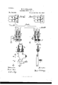
In the drawings illustrating my invention, Figures 1 and 1 represent sections of two multiple switchboards of the exchange to which the same lines are connected. Fig. 2 shows a diagram of the boards with the mainline apparatus and connections necessary to illustrate my invention. Fig. 3 shows a diagram of an operators cord system to be used in connection with the boards. Fig. 4 shows an operators test system to be used at the boards.
In Fig. 2, A is a sectional view of the switchboard shown in Fig. 1, and A is a sectional view of the switchboard shown in Fig 1", each as indicated by the line cl 6.
I place as many boards in the central ofiice as are found necessary or desirable in order to properly operate the exchange. On each board is a spring-jack or other suitable switch for each line. Each switch has a contactspring which normally connects with an insulated contact-piece and is adapted to receive a loop-plug and, when a plug is inserted, to disconnect the spring from the contactpiece and connect the two contact-pieces of the plug with the spring and said insulated contact-piece, respectively. The switch is also adapted to receive a single contact switch-plug and, when a plug is inserted, to disconnect the spring from the contact-piece and connect the spring with the contact-piece of the plug. In the construction of the switches as shown and as will hereinafter be described I prefer to have a contact-point electrically connected with the contact-piece and on which the spring normally bears, as there is less chance of poor connection when the spring bears on a point than when it bears on a surface adapted to be brought into connection with the plug-contacts.
In Fig. 2, g 9 represent the springs of the different switches, h h the contact-points on which the springs normally bear, and the contact-pieces of the switches connected with the points h h. Z Zare the switch-holes. a b are the rubber strips on which the metal parts of the switches are mounted, as shown, and through the fronts of which are the switch-holes Z Z. The contact-pieces j j are so placed along one of the surfaces of the plugholes as readily to form connection with one of the contact-pieces of the loop-plugs. The
holes Z Z are adapted to receive the switcl1- plugs shown in Fig. 3 and marked D D, and when a plug is inserted into a switch it raises the spring g from the contact-point h and the spring 9 and contact-piece of the plug are in contact. These holes are also adapted to receive the loop-plug shown in Fig. 4, and when a plug is inserted into a hole, it raises the spring of the switch from the contactpoint h and the spring g and the contactpiece j of the switch are in contact with the two contact-pieces of the plug, respectively.
w and w are calliiigannunciators, one for each of the lines shown. Two lines are shown in the drawings, one marked line No. 1 and the other line No. 2. These lines are ordinary single-circuit lines grounded at their outer ends and having at the subscribers stations any usual and appropriate subscribers-station apparatus. Each line passes successively through the pairs of contacts of its switches on the several boards, passing in each case to the spring first. It then passes through its line-annunciator to the ground. The circuit of each line shown may thus be traced in Fig. 2. I
In the operators cord system shown in Fig. 3, D D are the switch-plugs of a pair of cords. n n are the rubber insulations of the plugs, and m m are their contact-pieces. These contact-pieces pass each to the bottom of its plug and are adapted to rest normally, or when the of the line Wanted is rung.
plug is not in use, on the metal piece 0, which then connects it with the ground. Weights, as is usual, or similar devices maybe used to bring the contact-pieces of the plugs into contact with the piece 0 and secure a good connection. These plugs are adapted to be inserted into any of the switches at their board, and when a plug is inserted it operates the switch, as above described. The plugs should be inserted so that the contact-piece m is in contact with the spring g. The connections of the lines might have been reversed, so that the lines pass first to the contact-piece j of each of their switches, and in that case the plugs should be inserted in such a position that their contact pieces form connection with the piecesj of the switches. Y is the looping-in switch for the pair of cords shown. K is the calling-key. R is a resistance-coil, and 'v is a clearing-out annunciator. t is the operators telephone, and B is her calling generator or battery. The circuits are substantially as shown.
The two contact-pieces of the plugs are connected by flexible conductors to the two levers, respectively, of the looping-in switch. One of the pairs of contact-bolts of the switch are connected together through the clearingout annunciator and the other pair are connected through the operators telephone. The lever of the calling-key is connected to one of the cords, and the point of the key is grounded through the calling generator or battery. The resistance-coil is placed in the circuit of the other cord of the pair.
The operation of the system in connection with the switchboards will be apparent to those skilled in the art. I
It will readily be apparent that when a line is switched by the insertion of a plug into its switch the line is disconnected from its normal ground at the central oflice and is connected into a circuit with the pair of cords and that the resistance-coil of the pair of cords is in its circuit. Only one pair of cords are shown, but the connection of such other pairs, with their accompanying apparatus, as the operator may need, will be apparent to those skilled in the art.
The subscriber who desires a connection at the central oflice operates his calling-generator, as is usual. The annunciator of the line is thereby caused to indicate a call. The operator thereupon places one of the plugs D of a pair of plugs in the switch of the sub scribers line and, the switch Y of the pair of cords being in position, so that her telephone is in circuit with the pair of cords, finds out what line is wanted by the subscriber. When this is found out, she tests the line wanted, and if it is not in use she places the other plug of the pair into the switch of that line. The two subscribers lines are thereby included in a combined circuit. By pressing on her calling-key the subscribers bell The operator then moves the switch Y of the pair of cords so that the clearing-out annunciator o is in the circuit of the two lines connected together for conversation. When the subscribers are through conversation, either of them will operate his calling-generator in the usual manner to send a clearing-out signal to be indicated on the clearing-out annunciator left in the circuit of the lines.
To each pair of cords, with its plugs, belong a looping-in switch, a resistance-coil, a clearing-out annunciator, and a calling-key. One telephone and one calling-generator will answer for her system of cords. The plugs should be inserted into the switches of the lines so that the calling-key is connected to the circuit of the cords between the resistance-coil and the switch-plug inserted into the line whose bell it may be desired to ring. If desired, two calling-keys may be used for each pair of cords, one connected on each side of the resistance-coil.
It will also be seen that when two lines are left connected together for conversation both the clearing-out annunciator and the resistance-coil are in the circuit. The resistancecoil provides an all-metallic'circuit for the passage of the clearing-out current and also provides for the operation of the test system on a margin of operation, as will be hereinafter described. Its resistance is not, however, so great as in the ordinary forms of telephone-exchange apparatus to prevent the operation of the clearing-out annunciator.
In the operators test system shown in Fig. 4:, T is a loop test-plug adapted to be inserted into any of the switches and when inserted to operate them, as heretofore described. B is a test-battery, and S is a test receiving instrument. The battery and instrument are connected in a loop which terminates in the two contact-pieces of the plug.
Each operator has one cord system and one test system, and they are conveniently mounted and arranged for her work.
The test receiving instrument and battery should be so constructed, related to each other, and adj usted' that when they are looped into the circuit with any line and the circuit is not open at some pair of contact-points and does not have the resistance-coil in its circuit, as described, the instrument will sound or respond; but when the circuit is open at any point or has the resistance-coil connected, as described, in it the instrument will not sound or respond. This construction and adjustment depends on the fact that an electromagnet may be readily made so as to operate when a battery and a certain resistance is in circuit with it and not to operate when the resistance is considerably larger. This operation can be obtained in diiterent ways, dependent on the style of the electromagnet, the number of convolutions of its coil, the size of the battery, and the adjustment of the retractile spring. These parts should be and move its armature.
such that the electromagnet will be actuated when the test system islooped into the single circuit of any line of the exchange, but will not be actuated when the additional resistance of the resistance-coil is introduced. The resistance of this coil may be such as is necessary or desirable in order to obtain such a marginal adjustment of. the parts of the exchange system.
The operation of the test system is as follows: When an operator desires to test a line, she places her test-plug into the switch of the line and by so doing disconnects the pieces 9 and j of the switch and connects them with the contact-pieces of the plug. If, then, the line is not switched at any switch, the instrument and battery are on a closed circuit with the line, and the instrument will sound or respond, indicating that the line is free to be connected to. The instrument responds or sounds because the current is sufficiently strong to cause the electromagnet to attract If, however, the line is switched at any board when the test is made and the switch in which the test is made is in the cutoff portion of the line or that portion which is between the switch used for switching and the ofiice ground, the test-circuit is open at the pair of contacts 9 h of the switch used for switching, and the test receiving instrument will not sound, because the test receiving instrument and battery are in open circuit, and no current will pass through the instrument. If, again, the line is switched at any board and the test-plug is inserted into a switch which is between the one used and the subscribers station, the testcirenit has the resistance of the resistancecoil in the line, and the instrument will not sound,because, although the test receiving instrument and battery are then included in a complete metallic circuit and a current therefore passes through the test receiving i11- strument, yet on account of the high resistance of the circuit due to the introduction of the resistance-coil into the circuit the current is not strong enough to attract and move the armature of the test receiving instrument. The test is therefore obtained by the marginal adjustment of the test receiving instrument and battery to the circuits, such that when they are included in the normal closed circuit of the line the current is sufficiently strong to attract and move the armature of the test receiving instrument, but when the line is switched and the test receiving instrument and battery are included in it for testing the armature will not be moved, because, although current passes through the magnet of the test receiving instrument, it will not, on account of the high resistance of Y the resistance-coil included in its circuit, be
sufficiently strong to move its armature.
When a test of a line is made and the test receiving instrument sounds or responds, the operator therefore knows that the line is not switched for use at any board and that she may connect the line with another. When she makes the test and the instrument does not sound, she knows that the line is switched for use at some board and she will not connect it with another line.-
By the multiple-telephone-exchange system as a whole, as herein described, I obtain a system in which the lines test busy whenever they are switched for conversation and the sure the operation of the clearing-out annunjciator whenever the generator is operated for that purpose without the use of peculiar and extraordinary precautions therefor. This re suit is obtained by the use of a resistance. coil in the circuit of each pair of cords at the central office, which furnishes an all-metallic circuit for the passage of the clearing-out current from the subscribers generatorto facilitate the same and insure the operation of the clearing-out annunciator, and by the marginal adjustment of the test receiving instruments, as herein described, in connection therewith, whereby the correct test indication shall be made to the operator, although the circuit of the two lines shall be all metallic through the central office. I am aware that condensers (but not resistance-coils) have been placed in the circuit of pairs of cords at the central office to obtain a test indication. Such a system, however, did not provide an all-metallic circuit through the central office of two lines connected together to insure the operation of the clearing-out signal and had no marginal adjustment of the test receiving instruments, such as is herein described, to prevent a false test-signal being given when two lines are connected together in an a11- metallic circuit through the central office and the test receiving instrument and battery are included for testing into such circuit. My
system herein described and claimed has therefore obvious advantage over such prior system.
Of course the annunciators should be so related to the test circuits and batteries that they will not be operated when a test-battery is included in circuit with them. This may be provided for by having the annunciators polarized and so connected in the circuit and the batteries so connected in the circuit that the batteries will not operate the annunciators.
I claim as my invention and desire to secure by Letters Patent 1. In a telephone-exchange system, multiple. switchboards, telephone-lines grounded at their outer ends, normally on closed circuit and passing through a series of pairs of switchboard-contacts at the several boards, one pair ateach of the boards, and thence to ground, in combination with switching apparatus at each board to at the will of the op erator open the pair of normally closed con tacts of any two lines at that board and connect the lines into a closed circuit for conversation, a resistance-coil at the central office in the circuit of two lines when thus connected together, a clearing-out annunciator at the central office in the circuit with the two lines when thus connected together, a test receiving instrument at each board, testing devices connected therewith adapted at the will of the operator to open said contacts of any line at the board and loop said instrument into the normal line-circuit for testing said line, and battery in the closed circuit of any test receivinginstrument thus looped into circuit, the test receiving instruments being so adjusted to the circuits, resistances and battery by their marginal adjustment thereto, that each instrument sounds or responds when looped into the normal circuit of an unswitched line, but does not sound or respond when in an open circuit or in a closed circuit which contains one or both lines and said resistance-coil, whereby at the central office a circuit of metallic continuity is obtained for the clearing-out current of two lines connected together and the differentiation of the multiple-test signals is obtained by a marginal adjustment of the apparatus, substantially as set forth.
2. Vin a telephone-exchange system, multiple switchboards, telephone-lines, normally on closed circuit and passing through a series of pairs of switchboard-contacts at the several boards, one pair at each of the boards, in combination with switching apparatus at each board to at the will of the operator open the pair of normally closed contacts of any two lines at that board and connect the lines into a closedcircuit for conversation, a resistancecoil at the central office in the circuit of the two lines when thus connected together, a clearing-out annunciator at the central office in the circuit with the two lines when thus connected together, a test receiving instrument at each board, testing devices connected therewith adapted at the will of the operator to open said contacts of any line at the board and loop said instrument into the normal linecircuit for testing said line, and battery in the closed circuit of any test receiving instrument thus looped into circuit, the test receiving instruments being so adjusted to the circuits, resistances and battery by their marginal adjustment thereto, that each instrument sounds or responds when looped into the normal circuit of an unswitched line, but does not sound or respond when in anopen circuit min a closed circuit which contains one or both lines and said resistance-coil, whereby at the central office a circuit of metallic continuity is obtained for the clearingout current of two lines connected together and the. differentiation of the multiple -test signals is obtained by a marginal adjustment of the apparatus, substantially as set forth.
3. In a telephone-exchange system, multiple switchboards, telephone-lines grounded at their outer ends, normally on closed circuit and passing through a series of pairs of switchboard-contacts at the several boards, one pair at each of the boards, and thence to ground, in combination with switching apparatus at each board to at the will of the operator open the pair of normally closed contacts of any two lines at that board and connect the lines into a closed circuit for conversation, a resistance-coil at the central oflice in the circuit of the two lines when thus connected together, a clearing-out annunciator at the central oflice in the circuit with the two lines when thus connected together, and loop test-plugs, one at each board, each plug having two contact-pieces in which terminate the two sides of a loop containing a test receiving instrument and test-battery, each plug being adapted to be inserted into the switch of any line at its board and when inserted to open said switchboard-contacts of the line and connect them with the two contact-pieces of the plug respectively, the test receiving instruments being so adjusted to the circuits, resistances and battery by their marginal adjustment thereto, that each instrument sounds or responds when looped into the normal circuit of an unswitched line, but does not sound or respond when in an open circuit or in a closed circuit which contains one or both lines and said resistance-coil, whereby at the central office a circuit of metallic continuity is obtained for the clearing-out current of two lines connected together and the differentiation of the multiple-test signals is obtained by a marginal adjustment of the apparatus, substantially as set forth.
4. In a telephone-exchange system, multiple switchboards, telephone-lines, normally on closed circuit and passing through a series of pairs of switchboard-contacts at the several boards, one pair at each of the boards,
in combination with switching apparatus at each board to at the will of the operator open the pair of normally closed contacts of any two lines at that board and connect the lines into closed circuit for conversation, a resistance-coil in the circuit of the two lines when thus connected together, a clearing-out annunciator at the central office in the circuit with the two lines when thus. connected to- 'gether, and loop test-plugs, one at each board,
the circuits, resistances and battery by their marginal adjustment thereto, that each instrument sounds or responds when looped into the normal circuit of an unswitched line, but does not sound or respond when in an open circuit or in a closed circuit which contains one or both lines and said resistance-coil, In witnesswhereofIhereunto subscribe my whereby at the central cffice a circuit of mename this 13th day of December, 1889. tallic continuity is obtained for the clearingout current of two lines connected together MILO G. KELLOGG. and the differentiation of the multiple-test WVitnesses: signals is obtained by a marginal adjustment EMIL ABENHEIM,
of the apparatus, substantially as set forth. 1 MARGARETHA RIEHL.
Publications (1)
| Publication Number | Publication Date |
|---|---|
| US592354A true US592354A (en) | 1897-10-26 |
Family
ID=2661009
Family Applications (1)
| Application Number | Title | Priority Date | Filing Date |
|---|---|---|---|
| US592354D Expired - Lifetime US592354A (en) | Milo g |
Country Status (1)
| Country | Link |
|---|---|
| US (1) | US592354A (en) |
-
0
- US US592354D patent/US592354A/en not_active Expired - Lifetime
Similar Documents
| Publication | Publication Date | Title |
|---|---|---|
| US592354A (en) | Milo g | |
| US592404A (en) | Milo g | |
| US592348A (en) | Milo g | |
| US592358A (en) | Milo g | |
| US592400A (en) | kellogg | |
| US592353A (en) | Milo g | |
| US592347A (en) | Milo g | |
| US592320A (en) | Milo g | |
| US592372A (en) | Milo g | |
| US592325A (en) | Milo g | |
| US592385A (en) | Milo g | |
| US592366A (en) | Milo g | |
| US592356A (en) | Milo g | |
| US592381A (en) | Milo g | |
| US592396A (en) | Milo g | |
| US592363A (en) | kellogg | |
| US592351A (en) | Milo g | |
| US592355A (en) | Milo g | |
| US592403A (en) | Milo g | |
| US592346A (en) | Milo g | |
| US592398A (en) | Milo g | |
| US592378A (en) | Milo g | |
| US592340A (en) | Milo g | |
| US592350A (en) | Milo g | |
| US592425A (en) | Milo g |