BACKGROUND OF THE INVENTION
The present invention relates to cathode ray tube display devices with unnecessary radiating magnetic field reducing means which reduces an unnecessary radiating magnetic field due to a magnetic field leaking from deflection coils wound around a deflection yoke of a cathode ray tube such as a display monitor, and more particularly to measures to be taken against an unnecessary radiating magnetic field from a vertical deflection coil.
Unnecessary radiating magnetic fields which will be produced around a CRT display device, Visual Display Unit (VDU), are said to be reduced to within a predetermined value because detrimental effects to human bodies and/or electronic devices present in the unnecessary radiating magnetic fields are required to be prevented. Especially, for an unnecessary radiating magnetic field in a low frequency band below 400 kHz, there is guidelines, for example, called TCO which stipulates that an extremely low frequency magnetic field (ELMF) of 5 Hz-2 kHz and a very low frequency magnetic field (VLMF) of 2-400 kHz should be restricted to within 200 and 25 nT!, respectively, at each of a measuring point on the periphery of a circle having a radius of 50 cm! at whose center the VDU is situated and a measuring point distant by 30 cm! from the CRT tube face.
Since a main source for generating an unnecessary radiating magnetic field of such a low frequency band is the deflection yoke, many display devices are proposed which reduce the unnecessary radiating magnetic field to within a stipulated value, for example, by providing means in the deflection yoke for generating a magnetic field which cancels the unnecessary radiating magnetic field.
As a specified example, an unnecessary radiating magnetic field reducing device disclosed in JPA-3-289029 is provided with a first cancel coil connected in series or parallel with the horizontal reflection coil, and a second cancel coil connected in a series or parallel with the vertical deflection coil, the first and second cancel coils being disposed around the deflection yoke, so as to generate a canceling magnetic field opposite to an unnecessary radiating magnetic field from the deflection yoke to cancel the unnecessary radiating magnetic field.
FIG. 10 shows this conventional unnecessary radiating magnetic field reducing device. Reference numeral 1 denotes the deflection yoke; 2 a deflection coil bobbin; 3 the vertical deflection coil; and 4 a magnetic ferrite core; 55a, 55b, 56 each the cancel coil which cancels the unnecessary radiating magnetic field. The cancel coils 55a and 55b connected to the horizontal deflection coil and the cancel coil 56 connected to the vertical deflection coil 3 generate magnetic fields which cancel unnecessary radiating magnetic fields generated from the horizontal and vertical deflection coils depending on the respective horizontal and vertical scanning frequencies, respectively, to reduce the unnecessary radiating magnetic fields.
The setting positions of the cancel coils are distant from the unnecessary radiating magnetic field generating sources in the conventional unnecessary radiating magnetic field reducing device, so that there are large unnecessary radiating magnetic fields around the VDU which cannot be canceled by the cancel coils.
SUMMARY OF THE INVENTION
It is therefore an object of the present invention to reduce such unnecessary radiating magnetic fields efficiently and more particularly to provide a cathode ray tube display device with an unnecessary radiating magnetic field reducing means which greatly reduces unnecessary radiating magnetic fields which will be generated from the vertical deflection coil.
In order to achieve the above object, the present invention provides a cathode ray tube display device which includes a cathode ray tube to which a deflection yoke is attached, the deflection yoke having a horizontal and a vertical deflection coil for deflecting an electronic beam, and unnecessary radiating magnetic field reducing means for reducing an unnecessary radiating magnetic field due to a magnetic field leaking from the deflection yoke, said unnecessary radiating magnetic field reducing means comprising at least one pair of coils disposed in opposing relationship on the opposite sides of the ferrite core on or close to the outer peripheral surface of the ferrite core for generating a canceling magnetic field which opposes the unnecessary radiating magnetic field due to the magnetic field leaking from the deflection yoke.
BRIEF DESCRIPTION OF THE DRAWINGS
FIG. 1 is a top plan view of a deflection yoke with unnecessary radiating magnetic field reducing means as a first embodiment of the present invention;
FIG. 2 shows a distribution of a magnetic field generated by a vertical deflection coil;
FIG. 3 shows the difference in structure between the first embodiment and the conventional unnecessary radiating magnetic field reducing measures;
FIG. 4 shows the results of ELMF measurement by the first embodiment and the conventional unnecessary radiating magnetic field reducing measures;
FIG. 5 shows the relationship between coil inductance and ELMF for the first embodiment and the conventional unnecessary radiating magnetic field reducing measures;
FIG. 6 is a top plan view of a deflection yoke with unnecessary radiating magnetic field reducing means as a second embodiment of the present invention;
FIG. 7 is a top plan view of a deflection yoke in a third embodiment of the cathode ray tube display device according to the present invention;
FIG. 8 shows the result of measurement of the unnecessary radiating magnetic field of FIG. 7;
FIG. 9 is a top plan view of a deflection yoke in a fourth embodiment of the cathode ray tube display device according to the present invention; and
FIG. 10 is a plan view of an unnecessary magnetic field reducing device in the conventional cathode ray tube display device.
DESCRIPTION OF THE PREFERRED EMBODIMENTS
Preferred embodiments of the present invention will be described next with reference to the accompanying drawings.
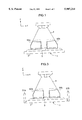
FIG. 1 is a top plan view of a deflection yoke with unnecessary radiating magnetic field reducing means as a first embodiment of the present invention. In FIG. 1, reference numeral 1 denotes a deflection yoke; 2 a deflection coil bobbin; 3 a vertical deflection coil; and 4 a ferrite core which increases a magnetic field effective for deflection of an electronic beam.
Reference numerals 50a and 50b denote a pair of coils disposed in opposing relationship on the opposite sides of a ferrite core 4 in an X-axis direction, that is, in the horizontal-axis direction of the deflection yoke 1 so as to be in contact with an open end (a larger diameter side) of the ferrite core 4. The pair of coils 50a, 50b composes the unnecessary radiating magnetic field reducing means.
The coils 50a and 50b each take a form similar to each other so as to have a shape curved with a predetermined radius of curvature conforming to the outer peripheral surface of the ferrite core 4. The respective lengths of the coils 50a and 50b in the X-axis direction are about one third of the periphery of the opening end of the deflection yoke 1. The length of one of the coils in the Z-axis direction, that is, in a direction perpendicular to the horizontal and vertical axes of the deflection yoke 1, is about one half of the length of the ferrite core 4 in the Z-axis direction.
FIG. 2 shows a distribution of a magnetic field generated by the vertical deflection coil 3 when a deflection current flows through the deflection yoke 1. In FIG. 2, a magnetic field 6 generated by the vertical deflection coil 3 in a space surrounded by the vertical deflection coil 3 is effective as a proper vertical deflection magnetic field. However, simultaneously, an unnecessary radiating magnetic field 7 would leak in a space outside the vertical deflection coil 3. The present invention is intended to reduce the unnecessary radiating magnetic field 7 sufficiently by generating a magnetic field opposing the unnecessary radiating magnetic field 7.
The effect of reducing the unnecessary radiating magnetic field in the first embodiment will be described next.
FIG. 3 shows the difference between the first embodiment and the conventional unnecessary radiating magnetic field measures. Reference numerals 51a and 51b each denote an air-core coil used in the conventional unnecessary radiating magnetic field measures.
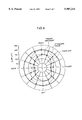
FIG. 4 shows the results of measurement of the ELMFs by the conventional unnecessary radiating magnetic field measures and the first embodiment on the basis of above-mentioned guidelines. Broken line plotting denotes the result of measurement of the ELMF by the conventional unnecessary radiating magnetic field measures, dot-dashed line plotting denotes the upper limits (200 nT!) of the standard values at the respective measuring points in the guidelines, and solid line plotting denotes the measured values of ELMF by the first embodiment.
In the ELMF measurement, the coil conditions employed which are the size, shape, and the numbers of coil turns are exactly the same as those employed in the first embodiment and the conventional measures.
In the first embodiment, the unnecessary radiating magnetic field is reduced by about 50 nT! in the horizontal direction where the ELMF is maximum compared to the conventional unnecessary radiating magnetic field measures. Also, in other directions, the first embodiment reduces the unnecessary radiating magnetic field by about 20-50 nT! compared to the conventional unnecessary radiating magnetic field measures.
FIG. 5 shows the results of actual measurement of the inductances of the coils 50a and 50b in the first embodiment and, for example, the inductances of the air- core coils 51a and 51b of the conventional unnecessary radiating magnetic field measures, and plotting of the maxima of the measured data of ELMF at the respective measuring points based on the guidelines.
More specifically, FIG. 5 represents the ELMF obtained when a reference inductance whose value is 1.0 is the inductance L0 of an air-core coil disposed at a position free from the influence from the ferrite core 4 and L represents the inductance of the air- core coils 51a and 51b of the respective conventional unnecessary radiating magnetic field measures and the coils 50a and 50b of the first embodiment. That is, in FIG. 5, the vertical axis represents ELMF and the horizontal axis represents the values L/L0 obtained by dividing the inductance L of the coils 50a, 50b and 51a, 51b by the reference inductance L0.
In FIG. 5, the ratio of the inductance L of the air- core coils 51a and 51b of the conventional unnecessary radiating magnetic field measures to the reference inductance L0 is 1.008 and the ELMF (at a point Pc) at that time is 205 nT! which is larger than the upper limit (200 nT!) of the standard value of the guidelines.
In contrast, the ratio of the inductance L of the air- core coils 50a and 50b of the first embodiment to the inductance L0 of the air-core coil is 1.726 and the ELMF (at point P1) at that time is 150 nT! which is smaller than the standard value of the guidelines.
In FIG. 5, it will be seen that the ELMF satisfies the standard value of the guidelines by disposing the unnecessary radiating magnetic field reducing coils 50a and 50b close to the ferrite core 4 such that the inductance L of the coils 50a and 50b of the first embodiment is 1.1 times L0.
As described above, by disposing the unnecessary radiating magnetic field reducing coils 50a and 50b close to the ferrite core 4 or in the direction in which the inductance of the unnecessary radiating magnetic field reducing coils 50a and 50b increases, the ferrite core 4 acts as a magnetic material body for the unnecessary radiating magnetic field reducing coils 50a and 50b to increase the inductance of the coils to thereby produce a large ELMF reducing effect.
The number of turns of coils 50a, 50b can be reduced until ELMF becomes the upper limit (200 nT!) of the guideline standard value because the large ELMF reducing effect is produced by the first embodiment. The size of the coils 50a and 50b can be reduced until the upper limit is reached.
According to the first embodiment, it is not required to insert ferromagnets into the corresponding coils 50a and 50b to increase a canceling magnetic field as in the conventional unnecessary radiating magnetic field measures described above. Thus, the cost of the unnecessary radiating magnetic field reducing means is reduced.
That is, according to the first embodiment, a cathode ray tube display device with unnecessary radiating magnetic field reducing means is provided which improves the ability to reduce the unnecessary radiating magnetic field, especially, generated by the vertical deflection coil although it is small and inexpensive.
FIG. 6 is a top plan view of a deflection yoke with unnecessary radiating magnetic field reducing means as a second embodiment of the present invention. In FIG. 6, the coils 52a and 52b as the unnecessary radiating magnetic field reducing means each are of the flat type and are disposed in contact with the open end of the ferrite core 4 in opposing relationship on the opposite sides of the ferrite core 4. In this case, as shown by the other embodiment P2 of FIG. 5, the ratio of the inductance L of the coils 52a and 52b to the reference inductance L0 is 1.193 and the ELMF in that case is 188 nT! which is below the guideline standard value.
The second embodiment also produces effects similar to those produced by the first embodiment.
While the first and second embodiments of the present invention described above are means for reducing unnecessary radiating magnetic field leaking mainly from the vertical deflection coil, the present invention is also effective as means for reducing an unnecessary radiating magnetic field leaking from the horizontal deflection coil. To this end, the coils 50a and 50b of FIG. 1 are required to be disposed in contact with the open end (larger diameter side) of the ferrite core 4 in opposing relationship on the ferrite core 4 in the Y-axis direction or in the vertical axis direction of the deflection yoke 1. By such composition, an unnecessary radiating magnetic field leaking from the horizontal reflection coil is greatly reduced.
Alternatively, a (first) pair of coils may be disposed in contact with the open end (larger diameter side) of the ferrite core 4 in opposing relationship on the opposite sides of the ferrite core 4 in the X-axis direction or in the horizontal axis direction of the deflection yoke 1 and another (second) pair of coils may be disposed in contact with the open end of the ferrite core 4 in opposing relationship on the opposite sides of the ferrite core 4 in the Y-axis direction or in the vertical axis direction of the deflection yoke 1.
FIG. 7 is a plan view of a deflection yoke in a third embodiment of the cathode ray tube display device according to the present invention. Reference numeral 1 denotes a deflection yoke; 3 a vertical deflection coil; 31 an open side fringe of the vertical deflection coil 3; 32 a neck side fringe of the vertical deflection coil 3; 4 a ferrite core; 53a, 53b each cancel the ferrite coil which cancels an unnecessary radiating magnetic field from the vertical deflection coil 3; 33 a spacing between the ferrite core 4 and the open side fringe 31 of the vertical deflection coil 3; and 34 a spacing between the ferrite core 4 and the neck side fringe 32 of the vertical deflection coil 3.
FIG. 8 shows the result of actual measurement, for example, of ELMF in the cathode ray tube display device with the unnecessary radiating magnetic field reducing means of FIG. 7 according to the present invention in conformity to the TCO standard guidelines. In FIG. 8 1(a) denotes the measured ELMF values obtained when no unnecessary radiating magnetic field measures are taken whereas (b) shows the measured ELMF values obtained after the unnecessary radiating magnetic field reducing means according to the present invention is provided. As shown in (b), in the inventive cathode ray tube display device, the measured ELMF values are smaller than the TCO standard value (200 nT!) at all the measuring points, which indicates that expected effects were obtained.
As will be seen from the above, an unnecessary radiating magnetic field 7 due to a magnetic field leaking from the vertical deflection coil 3 is reduced efficiently by disposing the cancel coils 53a and 53b at positions where the unnecessary radiating magnetic field 7 is strong on a line parallel to the ferrite core 4 of the deflection yoke 1 between the open side end and neck side end of the deflection yoke 1, for example at positions close to the ferrite core 4 and the open side fringe 31 of the vertical deflection coil so as to face the spacing 33 between the ferrite core 4 and the open side fringe 31 of the vertical deflection coil 3.
Alternatively, the cancel coils 53a and 53b may be connected to an external circuit which supplies a current whose wave form is similar to that of a vertical deflection current without being connected to the vertical deflection coil 3.
A fourth embodiment will be described referring to FIG. 9. The features of this embodiment lie in that first cancel coils 53a and 53b are disposed at positions close to the magnetic ferrite core 4 and the open side fringe 31 of the vertical deflection coil 3 so as to face a spacing 33 between the ferrite core 4 and the open side fringe 31 of the vertical deflection coil 3, and that second cancel coils 54a and 54b are disposed at positions close to the ferrite core 4 and the neck side fringe 34 of the vertical deflection coil 3 so as to face a spacing 34 between the ferrite core 4 and the neck side fringe 32 of the vertical deflection coil 3.
Like the cancel coils 53a and 53b of the third embodiment, the second cancel coins 54a and 54b are disposed such that the position of the strong one of the canceling magnetic fields which will be generated by the second cancel coils 54a and 54b coincides with the spacing 34 between the ferrite core 4 and the neck side fringe 32. That is, unnecessary radiating magnetic field reducing means is provided which further reduces the unnecessary radiating magnetic field 7 due to the magnetic field leaking from the vertical deflection coil 3 reduced in the first embodiment.
The first and second cancel coils 53a, 53b and 54a, 54b are adjusted in size and the number of turns so as to minimize the unnecessary radiating magnetic field 7.
While in the above description reduction of the unnecessary radiating magnetic field 7 due to the leaking magnetic field from the vertical deflection coil 3 has been illustrated, the unnecessary radiating magnetic field is further reduced by providing in the deflection yoke 1 means for reducing the unnecessary radiating magnetic field which will be generated from the horizontal deflection coil. The means for reducing the unnecessary radiating magnetic field from the horizontal deflection coil may be arranged like the above-mentioned inventive cancel coils to improve the reducing effect, of course.
The cancel coils may take the form of a square or a shape curved in conformity to the outer periphery of the ferrite core.
According to the present invention, unnecessary radiating magnetic field reducing means is provided which includes at least a pair of coils disposed in opposing relationship on the opposite sides of the ferrite core of the deflection yoke on or close to the outer periphery of the ferrite core to generate a counter magnetic field which cancels the unnecessary radiating magnetic field due to the magnetic field leaking from the deflection yoke.
When the ferrite core is made of a magnetic material, the inductance of a pair of coils between which the ferrite core is present is greater than that of a corresponding pair of air-core coils. Thus, a large magnetic field which will cancel the unnecessary radiating magnetic field is generated without using another ferromagnetic ferrite core between the coils.
Thus, a cathode ray tube display device is realized which has unnecessary radiating magnetic field reducing means to improve the ability to reduce an unnecessary radiating magnetic field, especially, generated by the vertical deflection coil.