US5906477A - Suction noise muffler mounting apparatus for hermetic compressor - Google Patents
Suction noise muffler mounting apparatus for hermetic compressor Download PDFInfo
- Publication number
- US5906477A US5906477A US08/879,535 US87953597A US5906477A US 5906477 A US5906477 A US 5906477A US 87953597 A US87953597 A US 87953597A US 5906477 A US5906477 A US 5906477A
- Authority
- US
- United States
- Prior art keywords
- suction noise
- noise muffler
- head
- cylinder head
- fixing member
- Prior art date
- Legal status (The legal status is an assumption and is not a legal conclusion. Google has not performed a legal analysis and makes no representation as to the accuracy of the status listed.)
- Expired - Lifetime
Links
- 238000003825 pressing Methods 0.000 claims description 17
- 238000004519 manufacturing process Methods 0.000 abstract description 5
- 238000000034 method Methods 0.000 abstract description 5
- 238000003780 insertion Methods 0.000 description 11
- 230000037431 insertion Effects 0.000 description 11
- 238000010276 construction Methods 0.000 description 6
- 244000145845 chattering Species 0.000 description 2
- 238000007792 addition Methods 0.000 description 1
- 230000003247 decreasing effect Effects 0.000 description 1
- 230000000694 effects Effects 0.000 description 1
- 238000012986 modification Methods 0.000 description 1
- 230000004048 modification Effects 0.000 description 1
- 238000000926 separation method Methods 0.000 description 1
- 238000006467 substitution reaction Methods 0.000 description 1
Images


Classifications
-
- F—MECHANICAL ENGINEERING; LIGHTING; HEATING; WEAPONS; BLASTING
- F04—POSITIVE - DISPLACEMENT MACHINES FOR LIQUIDS; PUMPS FOR LIQUIDS OR ELASTIC FLUIDS
- F04B—POSITIVE-DISPLACEMENT MACHINES FOR LIQUIDS; PUMPS
- F04B39/00—Component parts, details, or accessories, of pumps or pumping systems specially adapted for elastic fluids, not otherwise provided for in, or of interest apart from, groups F04B25/00 - F04B37/00
- F04B39/14—Provisions for readily assembling or disassembling
-
- F—MECHANICAL ENGINEERING; LIGHTING; HEATING; WEAPONS; BLASTING
- F04—POSITIVE - DISPLACEMENT MACHINES FOR LIQUIDS; PUMPS FOR LIQUIDS OR ELASTIC FLUIDS
- F04B—POSITIVE-DISPLACEMENT MACHINES FOR LIQUIDS; PUMPS
- F04B39/00—Component parts, details, or accessories, of pumps or pumping systems specially adapted for elastic fluids, not otherwise provided for in, or of interest apart from, groups F04B25/00 - F04B37/00
- F04B39/0027—Pulsation and noise damping means
- F04B39/0055—Pulsation and noise damping means with a special shape of fluid passage, e.g. bends, throttles, diameter changes, pipes
- F04B39/0072—Pulsation and noise damping means with a special shape of fluid passage, e.g. bends, throttles, diameter changes, pipes characterised by assembly or mounting
-
- Y—GENERAL TAGGING OF NEW TECHNOLOGICAL DEVELOPMENTS; GENERAL TAGGING OF CROSS-SECTIONAL TECHNOLOGIES SPANNING OVER SEVERAL SECTIONS OF THE IPC; TECHNICAL SUBJECTS COVERED BY FORMER USPC CROSS-REFERENCE ART COLLECTIONS [XRACs] AND DIGESTS
- Y10—TECHNICAL SUBJECTS COVERED BY FORMER USPC
- Y10S—TECHNICAL SUBJECTS COVERED BY FORMER USPC CROSS-REFERENCE ART COLLECTIONS [XRACs] AND DIGESTS
- Y10S181/00—Acoustics
- Y10S181/403—Refrigerator compresssor muffler
-
- Y—GENERAL TAGGING OF NEW TECHNOLOGICAL DEVELOPMENTS; GENERAL TAGGING OF CROSS-SECTIONAL TECHNOLOGIES SPANNING OVER SEVERAL SECTIONS OF THE IPC; TECHNICAL SUBJECTS COVERED BY FORMER USPC CROSS-REFERENCE ART COLLECTIONS [XRACs] AND DIGESTS
- Y10—TECHNICAL SUBJECTS COVERED BY FORMER USPC
- Y10S—TECHNICAL SUBJECTS COVERED BY FORMER USPC CROSS-REFERENCE ART COLLECTIONS [XRACs] AND DIGESTS
- Y10S417/00—Pumps
- Y10S417/902—Hermetically sealed motor pump unit
Definitions
- the present invention relates to a suction noise muffler mounting apparatus for a hermetic compressor, and in particular to an improved suction noise muffler mounting apparatus for a hermetic compressor which is capable of more simply mounting a suction noise muffler to a cylinder head, for thus reducing the number of fabrication processes and increasing the productivity of a hermetic compressor.
- FIG. 1 is a perspective view illustrating the construction of a conventional suction noise muffler mounting apparatus for a hermetic compressor.
- a cylinder head 10 including a head body 11 includes a hole 12 formed in the upper portion of the head body 11, with the hole 12 vertically passing through the upper surface of the head body 11.
- a support section 13 having a predetermined height is formed at the periphery of the hole 12.
- a suction noise muffler 20 is mounted to a portion of the cylinder head 10 so as to reduce the noise generated in the compressor.
- An insertion section 22 is downwardly extended from the bottom of the suction noise muffler body 21 of the suction noise muffler 20 and is inserted into the hole 12 of the cylinder head 10.
- the insertion section 22 is tightly inserted into the hole 12 of the cylinder head 10.
- a support section 23 is formed between the bottom of the suction noise muffler body 21 and the insertion section 22.
- an elastic band 30 having a predetermined elastic force is used.
- the elastic band 30 includes holes 31 formed at both ends thereof with respect to a pressing section 32 formed in an intermediate portion of the elastic band 30.
- reference numeral 33 denotes screws. The screws 33 are inserted into the holes 31 of the elastic band 30.
- the insertion section 22 is inserted into the hole 12 formed in the upper portion of the cylinder head body 11 of the cylinder head 10. Thereafter, the pressing section 32 of the elastic band 30 is pushed toward the support section 23 of the suction noise muffler 20.
- the two screws 33 are inserted into the holes 31 of the elastic band 30, and then the elastic band 30 is fixed to the support section 13 of the cylinder head 10 by tightening the screws 33, so that the suction noise muffler 20 is mounted to the cylinder head 10.
- the conventional suction noise muffler mounting apparatus for a hermetic compressor has the following disadvantages.
- the screws 33 may be escaped from the cylinder head 10 due to the repeated chattering of the cylinder head 10 during the operation of the compressor, so that the suction noise muffler 20 is easily separated from the hole 12 of the cylinder head body 11.
- the suction noise muffler 20 is mounted to the cylinder head 10 by using a plurality of screws 33, the engaging force between the suction noise muffler 20 and the cylinder head 10 may become weak.
- a suction noise muffler mounting apparatus for a hermetic compressor which includes a suction noise muffler head having a protrusion having a predetermined height and formed on the upper surface thereof and integrally engaged to an upper end of the suction noise muffler, and a fixing member provided for mounting the suction noise muffler to a portion of the cylinder head, with said fixing member including a circular section having a bolt receiving hole into which a bolt is inserted, and a pressing section extended from the circular section and having a hole into which the protrusion of the suction noise muffler head is inserted for pressing the upper surface of the suction noise muffler head.
- a suction noise muffler mounting apparatus for a hermetic compressor which includes a fixing bolt mounted on the upper portion of the cylinder head, with said fixing bolt including an upper head portion, a lower head portion spaced apart from the upper head portion, a groove section formed between the upper head portion and the lower head portion and having a predetermined diameter smaller than those of the upper head portion and the lower head portion, and a flange section formed in a lower portion of the lower head, and a fixing member including a fixing member engaging section engaged to a cylinder head engaging portion formed in a side surface of the cylinder head, a pressing section formed in an intermediate portion of the fixing member and circularly protruded for pressing the upper portion of the cylinder head, and a fixing member connection section formed at a lower end of the fixing member and having a hole into which the fixing bolt is inserted.
- a suction noise muffler mounting apparatus for a hermetic compressor which includes a suction noise muffler head having an upper groove and lower groove formed in one side surface of the suction noise muffler head, and a fixing member for pressing the suction noise muffler head.
- FIG. 1 is a perspective view illustrating the construction of a conventional suction noise muffler mounting apparatus for a hermetic compressor
- FIGS. 2A through 2D are views illustrating a suction noise muffler mounting apparatus for a hermetic compressor according to a first embodiment of the present invention, of which:
- FIG. 2A is a front view illustrating a state that a suction noise muffler mounting apparatus for a hermetic compressor is mounted to a cylinder head;
- FIG. 2B is a plan view illustrating the construction of a suction noise muffler for a hermetic compressor
- FIG. 2C is a side view partially illustrating the suction noise muffler for a hermetic compressor.
- FIG. 2D is a plan view illustrating the construction of a fixing member for a suction noise muffler mounting apparatus of a hermetic compressor
- FIGS. 3A through 3C are views illustrating the construction of a suction noise muffler mounting apparatus for a hermetic compressor according to a second embodiment of the present invention, of which:
- FIG. 3A is a front view illustrating a state that a suction noise muffler for a hermetic compressor is mounted to a cylinder head;
- FIG. 3B is a side view illustrating a state that a suction noise muffler for a hermetic compressor is mounted to a cylinder head;
- FIG. 3C is a front view illustrating a fixing bolt disposed in a cylinder head
- FIGS. 4A through 4C are views illustrating the construction of a suction noise muffler mounting apparatus for a hermetic compressor according to a third embodiment of the present invention, of which:
- FIG. 4A is a front view illustrating a state that a suction noise muffler for a hermetic compressor is mounted to a cylinder head;
- FIG. 4B is a perspective view illustrating a suction noise muffler head for a suction noise muffler.
- FIG. 4C is a perspective view illustrating a fixing member for a suction noise muffler mounting apparatus for mounting a suction noise muffler for a hermetic compressor to a cylinder head.
- FIGS. 2A through 2D are views illustrating a suction noise muffler mounting apparatus for a hermetic compressor according to a first embodiment of the present invention.
- a cylinder body 100 includes a cylinder head 110.
- the cylinder head 110 is mounted to a portion of the cylinder body 100 by using four bolts 111.
- the cylinder head 110 includes a suction noise muffler 120 mounted to a portion thereof so as to reduce noise generated in the interior of the hermetic compressor.
- reference numeral 123 denotes a suction portion of the suction noise muffler 120.
- a suction noise muffler head 121 having a predetermined length is attached to the upper portion of the suction noise muffler 120.
- the suction noise muffler head 121 includes a protrusion 122 formed on the upper surface of the suction noise muffler head 121.
- a fixing member 130 is used.
- the fixing member 130 is directed to preventing the suction noise muffler 120 from being dislocated or separated from the cylinder head 110 due to the vibrations of the suction noise muffler 120.
- the fixing member 130 includes a circular section 131 having a bolt receiving hole 132 having a predetermined diameter, and a rectangular pressing section 133 having a hole 134 formed in the center portion thereof.
- one of four bolts 111 mounted on the upper surface of the cylinder head 110 is inserted into the bolt receiving hole 132 formed in the circular section 131 of the fixing member 130.
- one of four bolts 111 mounted on the upper surface of the cylinder head 110 is untightened, and is inserted into the bolt receiving hole 132 formed in the circular section 131 of the fixing member 130. Thereafter, the protrusion 122 formed on the upper surface of the suction noise muffler head 121 of the suction noise muffler 120 is inserted into the hole 134 formed in the upper surface of the pressing section 133 of the fixing member 130. Next, the bolt 111 inserted into the bolt receiving hole 132 of the fixing member 13 is tightened. Therefore, the pressing section 133 of the fixing member 130 presses the upper portion of the suction noise muffler head 121, so that the suction noise muffler 120 is more tightly and stably mounted on the cylinder head 110.
- FIGS. 3A through 3D a suction noise muffler mounting apparatus for a hermetic compressor according to a second embodiment of the present invention will now be explained with reference to FIGS. 3A through 3D.
- FIG. 3A is a front view illustrating a state that a suction noise muffler for a hermetic compressor is mounted to a cylinder head.
- a suction noise muffler (not shown) having a suction noise muffler head 210 is mounted to a portion of a cylinder head 200, with the upper portion of the suction noise muffler head 210 being circular.
- the suction noise muffler head 210 is protruded by a predetermined height.
- three bolts 220, 221, and 222 and a fixing bolt 223 are mounted on the side surface of the cylinder head 200.
- the fixing bolt 223 includes a bolt body 224, a flange section 225 formed near the bolt body 224 and having a greater diameter than the bolt body 224, a lower head 226, and an upper head 227.
- a groove section 228 having a smaller diameter than the lower head 226 and the upper head 227 is formed between the lower head 226 and the upper head 227.
- a fixing member 240 is used for pressing the upper portion of the suction noise muffler head 210.
- the fixing member 240 includes a fixing member connection portion 241 formed in the lower end of the fixing member 240.
- a hole (not shown) is formed in the fixing member connection portion 241 of the fixing member 240 in order for the groove section 228 of the fixing bolt 223 to be inserted into the hole formed in the fixing member connection portion 241.
- a semicircular-shaped pressing section 242 is formed in the intermediate portion of the fixing member 240.
- the pressing section 242 serves to press the upper portion of the suction noise muffler head 210.
- the fixing member 240 includes a fixing member engaging section 243 formed in the upper end of the fixing member 240.
- the fixing member engaging section 243 is engaged to a cylinder head engaging section 244 formed in a side surface of the cylinder head 200.
- reference 245 denotes a head cover for covering the upper portion of the cylinder head 200.
- the groove section 228 formed in the fixing bolt 223 of the cylinder head 200 is inserted into the hole (not shown) formed in the fixing member connection portion 241 of the fixing member 240.
- the fixing member engaging section 243 of the fixing member 240 is pushed and is engaged to the cylinder head engaging section 244.
- the bolt 221 is completely covered by the fixing member 240, and the pressing section 242 of the fixing member 240 presses the upper portion of the suction noise muffler head 210.
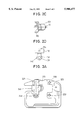
- FIGS. 4A through 4C a suction noise muffler mounting apparatus for a hermetic compressor according to a third embodiment of the present invention will now be explained with reference to FIGS. 4A through 4C.
- the suction noise muffler head 300 includes a parallel upper groove 301 and lower groove 302 each having a predetermined width and formed on one side surface thereof.
- a fixing member 400 is shown in FIG. 4C.
- the fixing member 400 includes symmetrical upper and lower bolt holes 401 and 402.
- a protruded section 403 is formed between the upper and lower bolt holes 401 and 402.
- the protruded section 403 includes an upper groove insertion section 404 and a lower groove insertion section 405 integrally formed at both sides of the protruded section 403.
- the upper groove insertion section 404 of the fixing member 400 is inserted into the upper groove 301 of the suction noise muffler head 300, and the lower groove insertion section 405 of the fixing member 400 is inserted into the lower groove 302 of the suction noise muffler head 300.
- reference numeral 310 denotes an upper bolt which is inserted into the upper bolt hole 401 of the fixing member 400
- reference numeral 320 denotes a lower bolt which is inserted into the lower bolt hole 402 of the fixing member 400.
- the fixing member 400 is placed above the suction noise muffler head 300.
- the upper bolt 310 is inserted into the upper bolt hole 401, and the lower bolt 320 is inserted into the lower bolt hole 402, for thus mounting the fixing member 400 to the cylinder head 200.
- the upper groove insertion section 404 and the lower groove insertion section 405 formed in the protruded section 403 of the fixing member 400 are inserted into the upper groove 301 and the lower groove 302, respectively. Therefore, the fixing member 400 is more stably mounted to the suction noise muffler head 300.
- the suction noise muffler mounting apparatus for a hermetic compressor has the following advantages.
Landscapes
- Engineering & Computer Science (AREA)
- Mechanical Engineering (AREA)
- General Engineering & Computer Science (AREA)
- Compressor (AREA)
Abstract
An improved suction noise muffler mounting apparatus for a hermetic compressor which is capable of more simply mounting a suction noise muffler to a cylinder head, for thus reducing the number of fabrication processes and increasing the productivity of a hermetic compressor, which includes a suction noise muffler head having a protrusion having a predetermined height and formed on the upper surface thereof and integrally engaged to an upper end of the suction noise muffler, and a fixing member provided for mounting the suction noise muffler to a portion of the cylinder head.
Description
This is a division of application Ser. No. 08/748,525, filed Nov. 4, 1996, now U.S. Pat. No. 5,707,216.
1. Field of the Invention
The present invention relates to a suction noise muffler mounting apparatus for a hermetic compressor, and in particular to an improved suction noise muffler mounting apparatus for a hermetic compressor which is capable of more simply mounting a suction noise muffler to a cylinder head, for thus reducing the number of fabrication processes and increasing the productivity of a hermetic compressor.
2. Description of the Conventional Art
FIG. 1 is a perspective view illustrating the construction of a conventional suction noise muffler mounting apparatus for a hermetic compressor.
As shown therein, a cylinder head 10 including a head body 11 includes a hole 12 formed in the upper portion of the head body 11, with the hole 12 vertically passing through the upper surface of the head body 11. In addition, a support section 13 having a predetermined height is formed at the periphery of the hole 12.
In addition, a suction noise muffler 20 is mounted to a portion of the cylinder head 10 so as to reduce the noise generated in the compressor. An insertion section 22 is downwardly extended from the bottom of the suction noise muffler body 21 of the suction noise muffler 20 and is inserted into the hole 12 of the cylinder head 10. Here, the insertion section 22 is tightly inserted into the hole 12 of the cylinder head 10. A support section 23 is formed between the bottom of the suction noise muffler body 21 and the insertion section 22.
When mounting the suction noise muffler 20 to the cylinder head 30, an elastic band 30 having a predetermined elastic force is used.
The elastic band 30 includes holes 31 formed at both ends thereof with respect to a pressing section 32 formed in an intermediate portion of the elastic band 30. In addition, in FIG. 1, reference numeral 33 denotes screws. The screws 33 are inserted into the holes 31 of the elastic band 30.
The assembling order of the conventional suction noise muffler mounting apparatus for a hermetic compressor will now be explained with reference to the accompanying drawings.
First, the insertion section 22 is inserted into the hole 12 formed in the upper portion of the cylinder head body 11 of the cylinder head 10. Thereafter, the pressing section 32 of the elastic band 30 is pushed toward the support section 23 of the suction noise muffler 20. The two screws 33 are inserted into the holes 31 of the elastic band 30, and then the elastic band 30 is fixed to the support section 13 of the cylinder head 10 by tightening the screws 33, so that the suction noise muffler 20 is mounted to the cylinder head 10.
However, the conventional suction noise muffler mounting apparatus for a hermetic compressor has the following disadvantages.
First, in a state that the insertion section 22 of the suction noise muffler 20 is inserted into the hole 12 of the cylinder head 10, since the pressing section of the elastic band 30 is pushed toward the support section 23 of the suction noise muffler 20, and the suction noise muffler 20 is fixed to the cylinder head 10 by using the screws 33, the screws 33 may be escaped from the cylinder head 10 due to the repeated chattering of the cylinder head 10 during the operation of the compressor, so that the suction noise muffler 20 is easily separated from the hole 12 of the cylinder head body 11.
Second, since the suction noise muffler 20 is mounted to the cylinder head 10 by using a plurality of screws 33, the engaging force between the suction noise muffler 20 and the cylinder head 10 may become weak.
Third, since the elastic band 30 and the screws 33 are additionally used in order to mount the suction noise muffler 20 to the cylinder head 10, the number of parts is disadvantageously increased, for thus increasing the cost of the hermetic compressor.
Fourth, since the number of parts is increased, the assembly process is increased thereby, for thus decreasing the productivity of the hermetic compressor.
Accordingly, it is an object of the present invention to provide a suction noise muffler mounting apparatus for a hermetic compressor which overcomes the problems encountered in the conventional suction noise muffler mounting apparatus for a hermetic compressor.
It is another object of the present invention to provide an improved suction noise muffler mounting apparatus for a hermetic compressor which is capable of more simply mounting a suction noise muffler to a cylinder head, for thus reducing the number of fabrication processes and increasing the productivity of a hermetic compressor.
To achieve the above objects, in accordance with a first embodiment of the present invention, there is provided a suction noise muffler mounting apparatus for a hermetic compressor which includes a suction noise muffler head having a protrusion having a predetermined height and formed on the upper surface thereof and integrally engaged to an upper end of the suction noise muffler, and a fixing member provided for mounting the suction noise muffler to a portion of the cylinder head, with said fixing member including a circular section having a bolt receiving hole into which a bolt is inserted, and a pressing section extended from the circular section and having a hole into which the protrusion of the suction noise muffler head is inserted for pressing the upper surface of the suction noise muffler head.
To achieve the above objects, in accordance with a second embodiment of the present invention, there is provided a suction noise muffler mounting apparatus for a hermetic compressor which includes a fixing bolt mounted on the upper portion of the cylinder head, with said fixing bolt including an upper head portion, a lower head portion spaced apart from the upper head portion, a groove section formed between the upper head portion and the lower head portion and having a predetermined diameter smaller than those of the upper head portion and the lower head portion, and a flange section formed in a lower portion of the lower head, and a fixing member including a fixing member engaging section engaged to a cylinder head engaging portion formed in a side surface of the cylinder head, a pressing section formed in an intermediate portion of the fixing member and circularly protruded for pressing the upper portion of the cylinder head, and a fixing member connection section formed at a lower end of the fixing member and having a hole into which the fixing bolt is inserted.
To achieve the above objects, in accordance with a third embodiment of the present invention, there is provided a suction noise muffler mounting apparatus for a hermetic compressor which includes a suction noise muffler head having an upper groove and lower groove formed in one side surface of the suction noise muffler head, and a fixing member for pressing the suction noise muffler head.
Additional advantages, objects and features of the invention will become more apparent from the description which follows.
The present invention will become more fully understood from the detailed description given hereinbelow and the accompanying drawings which are given by way of illustration only, and thus are not limitative of the present invention, and wherein:
FIG. 1 is a perspective view illustrating the construction of a conventional suction noise muffler mounting apparatus for a hermetic compressor;
FIGS. 2A through 2D are views illustrating a suction noise muffler mounting apparatus for a hermetic compressor according to a first embodiment of the present invention, of which:
FIG. 2A is a front view illustrating a state that a suction noise muffler mounting apparatus for a hermetic compressor is mounted to a cylinder head;
FIG. 2B is a plan view illustrating the construction of a suction noise muffler for a hermetic compressor;
FIG. 2C is a side view partially illustrating the suction noise muffler for a hermetic compressor; and
FIG. 2D is a plan view illustrating the construction of a fixing member for a suction noise muffler mounting apparatus of a hermetic compressor;
FIGS. 3A through 3C are views illustrating the construction of a suction noise muffler mounting apparatus for a hermetic compressor according to a second embodiment of the present invention, of which:
FIG. 3A is a front view illustrating a state that a suction noise muffler for a hermetic compressor is mounted to a cylinder head;
FIG. 3B is a side view illustrating a state that a suction noise muffler for a hermetic compressor is mounted to a cylinder head; and
FIG. 3C is a front view illustrating a fixing bolt disposed in a cylinder head;
FIGS. 4A through 4C are views illustrating the construction of a suction noise muffler mounting apparatus for a hermetic compressor according to a third embodiment of the present invention, of which:
FIG. 4A is a front view illustrating a state that a suction noise muffler for a hermetic compressor is mounted to a cylinder head;
FIG. 4B is a perspective view illustrating a suction noise muffler head for a suction noise muffler; and
FIG. 4C is a perspective view illustrating a fixing member for a suction noise muffler mounting apparatus for mounting a suction noise muffler for a hermetic compressor to a cylinder head.
FIGS. 2A through 2D are views illustrating a suction noise muffler mounting apparatus for a hermetic compressor according to a first embodiment of the present invention.
As shown therein, a cylinder body 100 includes a cylinder head 110. The cylinder head 110 is mounted to a portion of the cylinder body 100 by using four bolts 111. The cylinder head 110 includes a suction noise muffler 120 mounted to a portion thereof so as to reduce noise generated in the interior of the hermetic compressor.
In the drawings, reference numeral 123 denotes a suction portion of the suction noise muffler 120.
A suction noise muffler head 121 having a predetermined length is attached to the upper portion of the suction noise muffler 120. The suction noise muffler head 121 includes a protrusion 122 formed on the upper surface of the suction noise muffler head 121.
In order to prevent the chattering or dislocation of the suction noise muffler 120 after the suction noise muffler 120 is mounted to the cylinder head 110, a fixing member 130 is used. In other words, the fixing member 130 is directed to preventing the suction noise muffler 120 from being dislocated or separated from the cylinder head 110 due to the vibrations of the suction noise muffler 120.
The fixing member 130 includes a circular section 131 having a bolt receiving hole 132 having a predetermined diameter, and a rectangular pressing section 133 having a hole 134 formed in the center portion thereof.
In more detail, one of four bolts 111 mounted on the upper surface of the cylinder head 110 is inserted into the bolt receiving hole 132 formed in the circular section 131 of the fixing member 130.
The assembling order of the suction noise muffler mounting apparatus for a hermetic compressor according to the present invention will now be explained with reference to FIGS. 2A through 2D.
First, one of four bolts 111 mounted on the upper surface of the cylinder head 110 is untightened, and is inserted into the bolt receiving hole 132 formed in the circular section 131 of the fixing member 130. Thereafter, the protrusion 122 formed on the upper surface of the suction noise muffler head 121 of the suction noise muffler 120 is inserted into the hole 134 formed in the upper surface of the pressing section 133 of the fixing member 130. Next, the bolt 111 inserted into the bolt receiving hole 132 of the fixing member 13 is tightened. Therefore, the pressing section 133 of the fixing member 130 presses the upper portion of the suction noise muffler head 121, so that the suction noise muffler 120 is more tightly and stably mounted on the cylinder head 110.
Next, a suction noise muffler mounting apparatus for a hermetic compressor according to a second embodiment of the present invention will now be explained with reference to FIGS. 3A through 3D.
FIG. 3A is a front view illustrating a state that a suction noise muffler for a hermetic compressor is mounted to a cylinder head. As shown therein, a suction noise muffler (not shown) having a suction noise muffler head 210 is mounted to a portion of a cylinder head 200, with the upper portion of the suction noise muffler head 210 being circular. The suction noise muffler head 210 is protruded by a predetermined height. In addition, three bolts 220, 221, and 222 and a fixing bolt 223 are mounted on the side surface of the cylinder head 200.
As shown in FIG. 3C, the fixing bolt 223 includes a bolt body 224, a flange section 225 formed near the bolt body 224 and having a greater diameter than the bolt body 224, a lower head 226, and an upper head 227. A groove section 228 having a smaller diameter than the lower head 226 and the upper head 227 is formed between the lower head 226 and the upper head 227.
In addition, a fixing member 240 is used for pressing the upper portion of the suction noise muffler head 210. As shown in FIG. 3B, the fixing member 240 includes a fixing member connection portion 241 formed in the lower end of the fixing member 240. A hole (not shown) is formed in the fixing member connection portion 241 of the fixing member 240 in order for the groove section 228 of the fixing bolt 223 to be inserted into the hole formed in the fixing member connection portion 241. In addition, a semicircular-shaped pressing section 242 is formed in the intermediate portion of the fixing member 240. The pressing section 242 serves to press the upper portion of the suction noise muffler head 210. The fixing member 240 includes a fixing member engaging section 243 formed in the upper end of the fixing member 240. The fixing member engaging section 243 is engaged to a cylinder head engaging section 244 formed in a side surface of the cylinder head 200. In the drawings, reference 245 denotes a head cover for covering the upper portion of the cylinder head 200.
The assembling order and effects of the suction noise muffler mounting apparatus for a hermetic compressor according to the second embodiment of the present invention will now be explained with reference to FIGS. 3A through 3C.
First, the groove section 228 formed in the fixing bolt 223 of the cylinder head 200 is inserted into the hole (not shown) formed in the fixing member connection portion 241 of the fixing member 240.
The fixing member engaging section 243 of the fixing member 240 is pushed and is engaged to the cylinder head engaging section 244.
Thereafter, the bolt 221 is completely covered by the fixing member 240, and the pressing section 242 of the fixing member 240 presses the upper portion of the suction noise muffler head 210.
Therefore, it is possible to more easily and stably mount the suction noise muffler to the cylinder head 200 in cooperation with the fixing member 240.
Next, a suction noise muffler mounting apparatus for a hermetic compressor according to a third embodiment of the present invention will now be explained with reference to FIGS. 4A through 4C.
First, the suction noise muffler head 300 includes a parallel upper groove 301 and lower groove 302 each having a predetermined width and formed on one side surface thereof. A fixing member 400 is shown in FIG. 4C. As shown therein, the fixing member 400 includes symmetrical upper and lower bolt holes 401 and 402. A protruded section 403 is formed between the upper and lower bolt holes 401 and 402. The protruded section 403 includes an upper groove insertion section 404 and a lower groove insertion section 405 integrally formed at both sides of the protruded section 403. Here, when mounting the fixing member 400 to the suction noise muffler head 300, the upper groove insertion section 404 of the fixing member 400 is inserted into the upper groove 301 of the suction noise muffler head 300, and the lower groove insertion section 405 of the fixing member 400 is inserted into the lower groove 302 of the suction noise muffler head 300.
In the drawings, reference numeral 310 denotes an upper bolt which is inserted into the upper bolt hole 401 of the fixing member 400, and reference numeral 320 denotes a lower bolt which is inserted into the lower bolt hole 402 of the fixing member 400.
Next, the assembling order of the suction noise muffler mounting apparatus for a hermetic compressor according to the third embodiment of the present invention will now be explained with reference to FIGS. 4A through 4C.
First, the fixing member 400 is placed above the suction noise muffler head 300. The upper bolt 310 is inserted into the upper bolt hole 401, and the lower bolt 320 is inserted into the lower bolt hole 402, for thus mounting the fixing member 400 to the cylinder head 200. Thereafter, the upper groove insertion section 404 and the lower groove insertion section 405 formed in the protruded section 403 of the fixing member 400 are inserted into the upper groove 301 and the lower groove 302, respectively. Therefore, the fixing member 400 is more stably mounted to the suction noise muffler head 300.
As described above, the suction noise muffler mounting apparatus for a hermetic compressor according to the present invention has the following advantages.
First, it is possible to more easily mount the suction noise muffler to the cylinder head by using the suction noise muffler mounting apparatus according to the present invention.
Second, it is possible to effectively prevent the suction noise muffler from being separated from the cylinder head, which separation is due to a scattering (vibrations) of the cylinder during the operation of the compressor.
Third, it is possible to reduce the number of fabrication processes of the hermetic compressor, and to more easily mount the suction noise muffler to the cylinder head, for thus increasing the productivity of the hermetic compressor.
Fourth, it is, possible to significantly reduce the fabrication cost of the hermetic compressor.
Although the preferred embodiments of the present invention have been disclosed for illustrative purposes, those skilled in the art will appreciate that various modifications, additions and substitutions are possible, without departing from the scope and spirit of the invention as recited in the accompanying claims.
Claims (1)
1. In a suction noise muffler mounting apparatus for hermetic compressor having a cylinder head, a plurality of bolts, and a suction noise muffler head disposed in a portion of a suction noise muffler provided for reducing noise generated in the interior of a compressor, a suction noise mounting apparatus for mounting the suction noise muffler to a portion of the cylinder head, comprising:
a fixing bolt mounted on the upper portion of the cylinder head, with said fixing bolt including:
an upper head portion;
a lower head portion spaced apart from the upper head portion;
a groove section formed between the upper head portion and the lower head portion and having a predetermined diameter smaller than those of the upper head portion and the lower head portion; and
a flange section formed in a lower portion of the lower head; and
a fixing member including:
a fixing member engaging section engaged to a cylinder head engaging portion formed in a side surface of the cylinder head;
a pressing section formed in an intermediate portion of the fixing member and circularly protruded for pressing the upper portion of the cylinder head; and
a fixing member connection section formed at a lower end of the fixing member and having a hole into which the fixing bolt is inserted.
Priority Applications (1)
| Application Number | Priority Date | Filing Date | Title |
|---|---|---|---|
| US08/879,535 US5906477A (en) | 1995-11-15 | 1997-06-20 | Suction noise muffler mounting apparatus for hermetic compressor |
Applications Claiming Priority (4)
| Application Number | Priority Date | Filing Date | Title |
|---|---|---|---|
| KR95-41504 | 1995-11-15 | ||
| KR1019950041504A KR0186169B1 (en) | 1995-11-15 | 1995-11-15 | Silencer fastening device for hermetic compressor |
| US08/740,525 US5707216A (en) | 1995-11-15 | 1996-11-04 | Suction noise muffler mounting apparatus for hermetic compressor |
| US08/879,535 US5906477A (en) | 1995-11-15 | 1997-06-20 | Suction noise muffler mounting apparatus for hermetic compressor |
Related Parent Applications (1)
| Application Number | Title | Priority Date | Filing Date |
|---|---|---|---|
| US08/740,525 Division US5707216A (en) | 1995-11-15 | 1996-11-04 | Suction noise muffler mounting apparatus for hermetic compressor |
Publications (1)
| Publication Number | Publication Date |
|---|---|
| US5906477A true US5906477A (en) | 1999-05-25 |
Family
ID=19434228
Family Applications (3)
| Application Number | Title | Priority Date | Filing Date |
|---|---|---|---|
| US08/740,525 Expired - Fee Related US5707216A (en) | 1995-11-15 | 1996-11-04 | Suction noise muffler mounting apparatus for hermetic compressor |
| US08/879,535 Expired - Lifetime US5906477A (en) | 1995-11-15 | 1997-06-20 | Suction noise muffler mounting apparatus for hermetic compressor |
| US08/880,089 Expired - Lifetime US5908287A (en) | 1995-11-15 | 1997-06-20 | Suction noise muffler mounting apparatus for hermetic compressor |
Family Applications Before (1)
| Application Number | Title | Priority Date | Filing Date |
|---|---|---|---|
| US08/740,525 Expired - Fee Related US5707216A (en) | 1995-11-15 | 1996-11-04 | Suction noise muffler mounting apparatus for hermetic compressor |
Family Applications After (1)
| Application Number | Title | Priority Date | Filing Date |
|---|---|---|---|
| US08/880,089 Expired - Lifetime US5908287A (en) | 1995-11-15 | 1997-06-20 | Suction noise muffler mounting apparatus for hermetic compressor |
Country Status (4)
| Country | Link |
|---|---|
| US (3) | US5707216A (en) |
| KR (1) | KR0186169B1 (en) |
| CN (3) | CN1273735C (en) |
| IN (1) | IN190538B (en) |
Cited By (2)
| Publication number | Priority date | Publication date | Assignee | Title |
|---|---|---|---|---|
| US6722467B1 (en) | 2002-08-28 | 2004-04-20 | Brunswick Corporation | Noise attenuator for an air supply system of an internal combustion engine |
| US7228935B2 (en) * | 2002-09-10 | 2007-06-12 | Andreas Stihl Ag & Co. Kg | Attachment pin for an exhaust-gas muffler |
Families Citing this family (3)
| Publication number | Priority date | Publication date | Assignee | Title |
|---|---|---|---|---|
| JP4492032B2 (en) * | 2003-03-27 | 2010-06-30 | パナソニック株式会社 | Hermetic compressor |
| CN100414098C (en) * | 2003-06-26 | 2008-08-27 | 乐金电子(天津)电器有限公司 | Suction silencer fixing device for hermetic compressor |
| DE602005001324T2 (en) * | 2004-03-26 | 2008-02-07 | Arcelik Anonim Sirketi | COMPRESSOR WITH SUCTION MUFFLER |
Citations (10)
| Publication number | Priority date | Publication date | Assignee | Title |
|---|---|---|---|---|
| US4415060A (en) * | 1981-02-24 | 1983-11-15 | Necchi, S.P.A. | Muffler for compressors |
| US4449610A (en) * | 1981-02-24 | 1984-05-22 | Necchi Societa Per Azioni | Muffler for compressor for refrigerating apparatuses |
| US4784581A (en) * | 1987-01-12 | 1988-11-15 | White Consolidated Industries, Inc. | Compressor head and suction muffler for hermetic compressor |
| US5201640A (en) * | 1991-05-28 | 1993-04-13 | Empresa Brasileira De Compressores S/A -Embraco | Suction muffler assembly for hermetic compressors |
| US5207564A (en) * | 1992-04-21 | 1993-05-04 | White Consolidated Industries, Inc. | Compressor head and suction muffler for hermetic compressor |
| US5304044A (en) * | 1990-03-06 | 1994-04-19 | Matsushita Refrigeration Company | Hermetic compressor |
| US5496156A (en) * | 1994-09-22 | 1996-03-05 | Tecumseh Products Company | Suction muffler |
| US5577898A (en) * | 1995-07-27 | 1996-11-26 | Samsung Electronics Co., Ltd. | Suction muffler arrangement for a hermetic reciprocating compressor |
| US5613842A (en) * | 1994-11-03 | 1997-03-25 | Necchi Compressori S.R.L. | Hermetically sealed motor compressor unit with a spring biased muffler |
| US5641949A (en) * | 1993-04-20 | 1997-06-24 | Matsushita Refrigeration Industries (S) Pte. Ltd. | Method and apparatus for coupling a cylinder head--suction muffler assembly in a compressor |
Family Cites Families (3)
| Publication number | Priority date | Publication date | Assignee | Title |
|---|---|---|---|---|
| US4313715A (en) * | 1979-12-21 | 1982-02-02 | Tecumseh Products Company | Anti-slug suction muffler for hermetic refrigeration compressor |
| USRE33902E (en) * | 1987-01-12 | 1992-04-28 | White Consolidated Industries, Inc. | Compressor head and suction muffler for hermetic compressor |
| US5099566A (en) * | 1990-02-23 | 1992-03-31 | Carrier Corporation | Method of precompressing a silencer for a centrifugal compressor |
-
1995
- 1995-11-15 KR KR1019950041504A patent/KR0186169B1/en not_active Expired - Fee Related
-
1996
- 1996-11-04 US US08/740,525 patent/US5707216A/en not_active Expired - Fee Related
- 1996-11-05 IN IN1927CA1996 patent/IN190538B/en unknown
- 1996-11-15 CN CNB011018526A patent/CN1273735C/en not_active Expired - Fee Related
- 1996-11-15 CN CN96120588A patent/CN1084846C/en not_active Expired - Fee Related
- 1996-11-15 CN CNB011018534A patent/CN1221736C/en not_active Expired - Fee Related
-
1997
- 1997-06-20 US US08/879,535 patent/US5906477A/en not_active Expired - Lifetime
- 1997-06-20 US US08/880,089 patent/US5908287A/en not_active Expired - Lifetime
Patent Citations (10)
| Publication number | Priority date | Publication date | Assignee | Title |
|---|---|---|---|---|
| US4415060A (en) * | 1981-02-24 | 1983-11-15 | Necchi, S.P.A. | Muffler for compressors |
| US4449610A (en) * | 1981-02-24 | 1984-05-22 | Necchi Societa Per Azioni | Muffler for compressor for refrigerating apparatuses |
| US4784581A (en) * | 1987-01-12 | 1988-11-15 | White Consolidated Industries, Inc. | Compressor head and suction muffler for hermetic compressor |
| US5304044A (en) * | 1990-03-06 | 1994-04-19 | Matsushita Refrigeration Company | Hermetic compressor |
| US5201640A (en) * | 1991-05-28 | 1993-04-13 | Empresa Brasileira De Compressores S/A -Embraco | Suction muffler assembly for hermetic compressors |
| US5207564A (en) * | 1992-04-21 | 1993-05-04 | White Consolidated Industries, Inc. | Compressor head and suction muffler for hermetic compressor |
| US5641949A (en) * | 1993-04-20 | 1997-06-24 | Matsushita Refrigeration Industries (S) Pte. Ltd. | Method and apparatus for coupling a cylinder head--suction muffler assembly in a compressor |
| US5496156A (en) * | 1994-09-22 | 1996-03-05 | Tecumseh Products Company | Suction muffler |
| US5613842A (en) * | 1994-11-03 | 1997-03-25 | Necchi Compressori S.R.L. | Hermetically sealed motor compressor unit with a spring biased muffler |
| US5577898A (en) * | 1995-07-27 | 1996-11-26 | Samsung Electronics Co., Ltd. | Suction muffler arrangement for a hermetic reciprocating compressor |
Cited By (2)
| Publication number | Priority date | Publication date | Assignee | Title |
|---|---|---|---|---|
| US6722467B1 (en) | 2002-08-28 | 2004-04-20 | Brunswick Corporation | Noise attenuator for an air supply system of an internal combustion engine |
| US7228935B2 (en) * | 2002-09-10 | 2007-06-12 | Andreas Stihl Ag & Co. Kg | Attachment pin for an exhaust-gas muffler |
Also Published As
| Publication number | Publication date |
|---|---|
| CN1314550A (en) | 2001-09-26 |
| CN1273735C (en) | 2006-09-06 |
| CN1158388A (en) | 1997-09-03 |
| IN190538B (en) | 2003-08-09 |
| CN1221736C (en) | 2005-10-05 |
| KR0186169B1 (en) | 1999-05-01 |
| KR970027821A (en) | 1997-06-24 |
| US5908287A (en) | 1999-06-01 |
| US5707216A (en) | 1998-01-13 |
| CN1492148A (en) | 2004-04-28 |
| CN1084846C (en) | 2002-05-15 |
Similar Documents
| Publication | Publication Date | Title |
|---|---|---|
| US6321890B1 (en) | Vibration reducing system for automotive vehicle | |
| US5636826A (en) | Vibration control device | |
| US5491892A (en) | Method and apparatus of mounting a package housing and ground strap | |
| US6517302B2 (en) | Modular clip | |
| US5906477A (en) | Suction noise muffler mounting apparatus for hermetic compressor | |
| US4267993A (en) | Arrangement for mounting speaker unit to vehicle panel | |
| JP2905654B2 (en) | Shield connector | |
| JPH10108336A (en) | Electrical junction box | |
| JPH0550789U (en) | Plate material mounting structure | |
| US6737796B2 (en) | Cathode-ray tube mounting apparatus | |
| KR960008361Y1 (en) | Signal Leakage Prevention Device of High Frequency Amplifier | |
| KR0132844Y1 (en) | A shiled case fixing device of monitor | |
| JP4024416B2 (en) | Speaker gasket | |
| KR970006254Y1 (en) | Supporting structure of car-stereo | |
| KR200245849Y1 (en) | Compressor mounting apparatus for a refrigerator | |
| JPH0576092A (en) | Horn speaker | |
| JPH018015Y2 (en) | ||
| KR20000012665U (en) | TV's CRT Fixture | |
| JPS6246390Y2 (en) | ||
| JPS6237973Y2 (en) | ||
| JPH0419828Y2 (en) | ||
| JPS597817Y2 (en) | Front frame mounting device | |
| JPH1151034A (en) | Fastening parts and combined spacer using these parts | |
| KR100446058B1 (en) | The Conclusion Structure of Mulitbox | |
| JPH0729442A (en) | Grommet bracket |
Legal Events
| Date | Code | Title | Description |
|---|---|---|---|
| STCF | Information on status: patent grant |
Free format text: PATENTED CASE |
|
| REMI | Maintenance fee reminder mailed | ||
| FPAY | Fee payment |
Year of fee payment: 4 |
|
| SULP | Surcharge for late payment | ||
| FPAY | Fee payment |
Year of fee payment: 8 |
|
| FEPP | Fee payment procedure |
Free format text: PAYOR NUMBER ASSIGNED (ORIGINAL EVENT CODE: ASPN); ENTITY STATUS OF PATENT OWNER: LARGE ENTITY |
|
| FPAY | Fee payment |
Year of fee payment: 12 |