US5899439A - Handle with adjustable stop for flow-control valve - Google Patents
Handle with adjustable stop for flow-control valve Download PDFInfo
- Publication number
- US5899439A US5899439A US08/753,313 US75331396A US5899439A US 5899439 A US5899439 A US 5899439A US 75331396 A US75331396 A US 75331396A US 5899439 A US5899439 A US 5899439A
- Authority
- US
- United States
- Prior art keywords
- knob
- housing
- abutment
- stem
- valve
- Prior art date
- Legal status (The legal status is an assumption and is not a legal conclusion. Google has not performed a legal analysis and makes no representation as to the accuracy of the status listed.)
- Expired - Fee Related
Links
Images


Classifications
-
- F—MECHANICAL ENGINEERING; LIGHTING; HEATING; WEAPONS; BLASTING
- F16—ENGINEERING ELEMENTS AND UNITS; GENERAL MEASURES FOR PRODUCING AND MAINTAINING EFFECTIVE FUNCTIONING OF MACHINES OR INSTALLATIONS; THERMAL INSULATION IN GENERAL
- F16K—VALVES; TAPS; COCKS; ACTUATING-FLOATS; DEVICES FOR VENTING OR AERATING
- F16K35/00—Means to prevent accidental or unauthorised actuation
- F16K35/02—Means to prevent accidental or unauthorised actuation to be locked or disconnected by means of a pushing or pulling action
- F16K35/027—Means to prevent accidental or unauthorised actuation to be locked or disconnected by means of a pushing or pulling action the locking mechanism being actuated by pushing or pulling the valve actuator, the valve actuator being rotated subsequently to bring the valve closure element in the desired position
Definitions
- the present invention relates to a handle for a flow-control valve. More particularly this invention concerns such a handle having an adjustable stop.
- a flow-control valve having a valve housing and a valve element in the housing rotatable about an axis through at most 360° between a fully open position for substantially unimpeded fluid flow through the housing and a fully closed position for substantially no fluid flow through the housing and through intermediate positions for intermediate levels of flow through the housing.
- a spindle coupled to the element extends along and is jointly pivotal with the element about the axis.
- a handle or knob fixed on the spindle is provided offset from the axis with a handle stop so that the handle stop orbits about the axis as the handle and spindle are rotated to adjust the valve.
- An abutment body or sleeve fixed on the housing adjacent the knob carries a housing stop that is radially deflectable on the abutment body between a normal position angularly engageable with the handle stop for limiting angular movement of the handle and spindle and a deflected position out of angular engagement with the handle stop and permitting unimpeded angular movement of the handle.
- the stop normally limits the angular stroke or travel of the valve spindle.
- This housing stop can, however, be depressed radially to let the handle stop pass, allowing the full range of adjustment to the handle.
- Another object is the provision of such an improved handle assembly for a flow-control valve which overcomes the above-given disadvantages, that is which is of simple construction and which is easy to operate.
- a valve has a valve housing and a stem projecting from the housing and rotatable relative thereto about an axis.
- a handle assembly for the valve has according to the invention an abutment directed angularly in one direction of the axis and fixed relative to the housing, a knob, and formations on the knob and stem for rotationally fixing the knob on the stem and for axial displacement of the knob on the stem between a normal use position and an override position.
- a knob abutment projecting axially from the knob is directed angularly opposite to the housing abutment. The knob abutment is angularly engageable with the housing abutment in the normal use position but is able to pass angularly past the housing abutment in the override position.
- the knob is in the normal use position most of the time. In order, however, to gain increased flow, a higher temperature, or divert water from the tub to the shower, the knob is displaced into the override position.
- the same knob used for flow control or temperature adjustment is simply pulled or pushed as it is turned, normally pulled for safety's sake, in order to go beyond the normal end position defined by engagement of the abutments with each other.
- the handle assembly according to the invention further has means, typically a simple compression spring, engaged between the knob and the valve housing for urging the knob into the normal use position.
- An abutment ring fixed on the valve housing according to the invention is formed centered on the axis with an angularly extending arcuate groove having an end constituting the housing abutment.
- the knob abutment engages into this groove in the normal use position.
- the knob abutment is a pin formed on the knob.
- the knob abutment is an angularly elongated and axially projecting rib formed on the knob.
- the knob is formed by an inner part axially and rotationally fixed on the spindle, and an outer part axially displaceable but nonrotatable on the inner part.
- the spring is braced axially between the inner and outer parts to urge the knob into the normal use position.
- the housing in accordance with this invention is provided with an axially extending sleeve centered on the axis and the outer part is formed with an axially open groove centered on the axis and axially slidably receiving the sleeve.
- the sleeve is provided with indicia and the outer part is formed with a pointer cooperating with the indicia.
- At least one screw fixes the sleeve on the valve housing and splines rotationally interconnect the inner and outer parts.
- one of the abutments extends at an acute angle to a plane including the axis so that the other abutment can be cammed axially by the one abutment.
- the knob according to the invention moves through a stroke of between 1 mm and 10 mm between its positions.
- the valve can be a flow-control valve, a temperature-control valve, or a diverter and flow-control valve and controls flow to one user in the normal position and to another user in the override position.
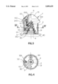
- FIG. 1 is a side view partly in axial section through the handle assembly in the normal use position
- FIG. 2 is a section taken along line II--II of FIG. 1.
- FIG. 3 is a view like FIG. 1 but with the valve in the override position;
- FIG. 4 is a section taken along line IV--IV of FIG. 3;
- FIG. 5 is a view in the direction of arrow V of FIG. 1;
- FIG. 6 is a sectional view of a detail of an alternative arrangement according to the invention.
- a handle assembly 1 is effective on a valve 4 having a housing 40 from which extends a stem 2 rotatable about an axis A but nondisplaceable along this axis A.
- An inner part or guide sleeve 20 is secured by a screw 201 to the stem 2 and has splines interfitting with splines on this stem 2 so that this inner part 20 is fixed against axial and angular movement on the stem 2.
- a knob outer part 11 is coupled by splines 200 to the inner part 20 so as to be rotationally coupled to it while being able to move axially on it through a stroke of 1 mm to 10 mm, preferably 3 mm.
- An abutment 10 formed as an axially downwardly projecting pin offset from the axis A is formed on the bottom of the outer part 11 as well as a lip or ledge 111 that extends underneath the inner part 20.
- abutment ring 3 secured by splines 111 in an outer valve housing element 31 having a base 312 secured by at least one screw 311 to the housing 40.
- This abutment ring 3 is formed as shown in FIG. 4 with an arcuate groove 30 having ends 301 forming abutments for the pin 10.
- the inner part 20 is formed above the lip 111 with an axially downwardly open annular groove 21 holding a compression spring 5 that is centered on the axis A and that bears axially outward the inner part 20 fixed to the stem 2 and axially inward the ledge 111 of the outer part 11.
- this spring 5 urges the outer part 11 down into the use position of FIG.
- the outer element 31 has an upwardly extending sleeve 310 that engages in a complementary groove 110 of the outer knob part 11 that is axially so deep that even in the raised override position of FIG. 3 the sleeve 310 is still well engaged in the groove 110.
- the outer knob part 11 carries a removable end cap 13 that covers up the screw 201 and that can provide a designer accent. It is also formed with a pointer 12 (FIG. 5) movable relative to indicia 313 on the outer housing element 31 so as to indicate the set position of the knob assembly 1.
- the knob head formed by the parts 11 and 20 is raised as indicated in FIG. 3. This pulls the pin 10 completely out of the groove 30 and allows movement of the knob parts 11 and 20 into any desired position, not limited by the travel of the abutment pin 10 in the abutment groove 30.
- the spring 5 automatically returns the valve to the normal use position, snapping the pin 10 into the groove 30 when they are again aligned with each other.
- the valve can be adjusted by removing the parts 11 and 20 and lifting out the ring 3 so that it can be reinstalled in a different angular position.
- the splines 111 permit it to be set in virtually any position.
- a groove 30' like the groove 30 has angled ends 301' that serve to cam up an abutment rib 10' and the element 11 it is formed on.
- the user need merely exert some extra force to adjust beyond the end position. This will cam up the abutment 10 and allow it to move angularly farther along.
- the difference in angular dimension between the rib 10' and the groove 30' determines the extent of adjustment in the normal use position.
- the knob assembly 1 can also be used on a simple flow-control valve 4 so as to provide an upper limit to the flow rate through the knob for energy-conservation purposes, this upper flow rate of course being overridable.
- the valve 4 can be a temperature-control valve with the end position serving a safety function to prevent the dispensing of water that is too hot. If the valve 4 is a tub/shower diverter valve it can normally operate to control flow to the tub, but when the knob outer part 11 is pulled and twisted into the override position, it diverts flow to the shower instead.
Landscapes
- General Engineering & Computer Science (AREA)
- Engineering & Computer Science (AREA)
- Mechanical Engineering (AREA)
- Mechanically-Actuated Valves (AREA)
- Mechanical Control Devices (AREA)
- Preventing Unauthorised Actuation Of Valves (AREA)
- Temperature-Responsive Valves (AREA)
- Axle Suspensions And Sidecars For Cycles (AREA)
- Water Treatment By Sorption (AREA)
- Synchronisation In Digital Transmission Systems (AREA)
- Organic Low-Molecular-Weight Compounds And Preparation Thereof (AREA)
- Domestic Plumbing Installations (AREA)
- Indication Of The Valve Opening Or Closing Status (AREA)
- Multiple-Way Valves (AREA)
- Surgical Instruments (AREA)
- Lock And Its Accessories (AREA)
Abstract
Description
Claims (15)
Applications Claiming Priority (2)
| Application Number | Priority Date | Filing Date | Title |
|---|---|---|---|
| DE19545587 | 1995-12-07 | ||
| DE19545587A DE19545587A1 (en) | 1995-12-07 | 1995-12-07 | Control handle |
Publications (1)
| Publication Number | Publication Date |
|---|---|
| US5899439A true US5899439A (en) | 1999-05-04 |
Family
ID=7779395
Family Applications (1)
| Application Number | Title | Priority Date | Filing Date |
|---|---|---|---|
| US08/753,313 Expired - Fee Related US5899439A (en) | 1995-12-07 | 1996-11-22 | Handle with adjustable stop for flow-control valve |
Country Status (7)
| Country | Link |
|---|---|
| US (1) | US5899439A (en) |
| EP (1) | EP0778434B1 (en) |
| JP (1) | JPH09177149A (en) |
| AT (1) | ATE171766T1 (en) |
| DE (2) | DE19545587A1 (en) |
| DK (1) | DK0778434T3 (en) |
| ES (2) | ES1035526Y (en) |
Cited By (11)
| Publication number | Priority date | Publication date | Assignee | Title |
|---|---|---|---|---|
| EP1124081A1 (en) * | 2000-02-10 | 2001-08-16 | Torrent Trading Ltd. | Tap |
| US6669170B2 (en) * | 2000-06-16 | 2003-12-30 | Unaxis Balzers Aktiengesellschaft | Vacuum valve |
| US20040079422A1 (en) * | 2002-10-23 | 2004-04-29 | Marty Garry Robin | Faucet manifold assembly with in-line integral stops |
| US20040206401A1 (en) * | 2003-04-17 | 2004-10-21 | Willi Hecking | Pressure reducer |
| GB2404720A (en) * | 2003-08-07 | 2005-02-09 | Neil Sim | Domestic tap with rotation limiting mechanism |
| US20080138749A1 (en) * | 2005-02-10 | 2008-06-12 | Inigo Albizuri | Multi-gas cooker, with a rotary valve provided with interchangeable regulating means |
| US20080178952A1 (en) * | 2007-01-31 | 2008-07-31 | Moen Incorporated | Valve cartridge with integral stop |
| US20090092126A1 (en) * | 2007-10-03 | 2009-04-09 | Verizon Data Services Inc. | Method and system for retrieving log messages from customer premise equipment |
| US20100154777A1 (en) * | 2008-12-19 | 2010-06-24 | Coprecitec, S.L. | Regulation valve |
| GB2575908A (en) * | 2018-06-06 | 2020-01-29 | Aquatica Nz Ltd | Tap or faucet with safety interlock for near-boiling and chilled water |
| IT202200006893A1 (en) * | 2022-04-07 | 2023-10-07 | Carlo Nobili S P A Rubinetterie | Manual adjustment device for water supply systems, in particular taps, showers and the like, with improved ergonomics. |
Families Citing this family (10)
| Publication number | Priority date | Publication date | Assignee | Title |
|---|---|---|---|---|
| KR20020028612A (en) * | 2000-10-11 | 2002-04-17 | 유인균 | construction method of unit house |
| DE102006045540A1 (en) * | 2006-09-25 | 2008-04-03 | Grohe Ag | Handle for a water valve |
| DK2225487T4 (en) † | 2007-12-15 | 2017-02-20 | Grohe Ag | Hot water faucet |
| DE102009012839A1 (en) | 2009-03-04 | 2010-10-14 | Hansgrohe Ag | Actuating arrangement for sanitary fittings |
| DE102009021185B4 (en) * | 2009-05-13 | 2013-03-07 | Grohe Ag | Turning handle for sanitary fitting |
| ES2697407T3 (en) | 2015-08-11 | 2019-01-23 | Ideal Standard Int Nv | Thermostat valve with a cap that has a forced guide |
| EP3540129B1 (en) * | 2018-03-12 | 2020-06-03 | Flühs Drehtechnik GmbH | Sanitary fitting |
| KR102027417B1 (en) * | 2018-08-22 | 2019-11-14 | 주식회사 동아아이디 | A showerhead having an injection quantity regulating device |
| DE102019128364A1 (en) | 2019-10-21 | 2021-04-22 | Horcher Gmbh | Valve arrangement |
| ES2993065T3 (en) * | 2022-05-13 | 2024-12-20 | Ideal Standard Int Nv | Adjusting unit for a thermostatic cartridge |
Citations (15)
| Publication number | Priority date | Publication date | Assignee | Title |
|---|---|---|---|---|
| DK40015C (en) * | 1927-10-01 | 1929-04-08 | Laerling Helmer Gu Christensen | Safety gas tap. |
| GB931202A (en) * | 1961-02-02 | 1963-07-10 | Radiation Ltd | Improvements in and relating to gas control valves |
| FR1514245A (en) * | 1967-01-09 | 1968-02-23 | Briffault Sa | Two way stopcock |
| US3693874A (en) * | 1970-11-27 | 1972-09-26 | Robertshaw Controls Co | Fuel control system and control device therefor or the like |
| NL7301756A (en) * | 1972-02-11 | 1973-08-14 | ||
| US4089347A (en) * | 1976-12-27 | 1978-05-16 | Masco Corporation Of Indiana | Mixing valve anti-scald apparatus |
| GB2133511A (en) * | 1983-01-11 | 1984-07-25 | Danfoss As | Fluid flow valves with preset throughflow |
| US4549716A (en) * | 1983-12-15 | 1985-10-29 | Warren Timothy P | Control handle arrangement for a fluid control valve |
| US4577831A (en) * | 1985-04-01 | 1986-03-25 | Sun Hydraulics Corporation | Calibrated handknob assembly |
| US4733688A (en) * | 1984-05-23 | 1988-03-29 | Hans Grohe Gmbh & Co. Kg | Mixer valve |
| US5082023A (en) * | 1989-10-31 | 1992-01-21 | Staar S. A. | Single-handle faucet |
| DE9209111U1 (en) * | 1992-07-08 | 1992-08-27 | Metallwerke Otto Dingerkus GmbH, 5952 Attendorn | Shut-off device, especially appliance connection tap |
| DE4308762A1 (en) * | 1993-03-19 | 1994-09-22 | Grohe Armaturen Friedrich | Flow-control valve |
| US5364065A (en) * | 1993-09-09 | 1994-11-15 | Tauati Reef L | Push control faucet handle |
| US5522429A (en) * | 1993-11-30 | 1996-06-04 | Friedrich Grohe Aktiengesellschaft | Stroke limiter for single-lever mixing valve |
-
1995
- 1995-12-07 DE DE19545587A patent/DE19545587A1/en not_active Withdrawn
-
1996
- 1996-11-04 ES ES09602799U patent/ES1035526Y/en not_active Expired - Lifetime
- 1996-11-13 JP JP8302034A patent/JPH09177149A/en active Pending
- 1996-11-20 ES ES96118556T patent/ES2124617T3/en not_active Expired - Lifetime
- 1996-11-20 DK DK96118556T patent/DK0778434T3/en active
- 1996-11-20 AT AT96118556T patent/ATE171766T1/en not_active IP Right Cessation
- 1996-11-20 EP EP96118556A patent/EP0778434B1/en not_active Expired - Lifetime
- 1996-11-20 DE DE59600626T patent/DE59600626D1/en not_active Expired - Fee Related
- 1996-11-22 US US08/753,313 patent/US5899439A/en not_active Expired - Fee Related
Patent Citations (16)
| Publication number | Priority date | Publication date | Assignee | Title |
|---|---|---|---|---|
| DK40015C (en) * | 1927-10-01 | 1929-04-08 | Laerling Helmer Gu Christensen | Safety gas tap. |
| GB931202A (en) * | 1961-02-02 | 1963-07-10 | Radiation Ltd | Improvements in and relating to gas control valves |
| FR1514245A (en) * | 1967-01-09 | 1968-02-23 | Briffault Sa | Two way stopcock |
| US3693874A (en) * | 1970-11-27 | 1972-09-26 | Robertshaw Controls Co | Fuel control system and control device therefor or the like |
| NL7301756A (en) * | 1972-02-11 | 1973-08-14 | ||
| US4089347A (en) * | 1976-12-27 | 1978-05-16 | Masco Corporation Of Indiana | Mixing valve anti-scald apparatus |
| GB2133511A (en) * | 1983-01-11 | 1984-07-25 | Danfoss As | Fluid flow valves with preset throughflow |
| US4549716A (en) * | 1983-12-15 | 1985-10-29 | Warren Timothy P | Control handle arrangement for a fluid control valve |
| US4733688A (en) * | 1984-05-23 | 1988-03-29 | Hans Grohe Gmbh & Co. Kg | Mixer valve |
| US4577831A (en) * | 1985-04-01 | 1986-03-25 | Sun Hydraulics Corporation | Calibrated handknob assembly |
| US5082023A (en) * | 1989-10-31 | 1992-01-21 | Staar S. A. | Single-handle faucet |
| DE9209111U1 (en) * | 1992-07-08 | 1992-08-27 | Metallwerke Otto Dingerkus GmbH, 5952 Attendorn | Shut-off device, especially appliance connection tap |
| DE4308762A1 (en) * | 1993-03-19 | 1994-09-22 | Grohe Armaturen Friedrich | Flow-control valve |
| US5421364A (en) * | 1993-03-19 | 1995-06-06 | Friedrich Grohe Aktiengesellschaft | Flow-control valve with handle-travel limited |
| US5364065A (en) * | 1993-09-09 | 1994-11-15 | Tauati Reef L | Push control faucet handle |
| US5522429A (en) * | 1993-11-30 | 1996-06-04 | Friedrich Grohe Aktiengesellschaft | Stroke limiter for single-lever mixing valve |
Cited By (32)
| Publication number | Priority date | Publication date | Assignee | Title |
|---|---|---|---|---|
| EP1124081A1 (en) * | 2000-02-10 | 2001-08-16 | Torrent Trading Ltd. | Tap |
| US6669170B2 (en) * | 2000-06-16 | 2003-12-30 | Unaxis Balzers Aktiengesellschaft | Vacuum valve |
| US20040079422A1 (en) * | 2002-10-23 | 2004-04-29 | Marty Garry Robin | Faucet manifold assembly with in-line integral stops |
| US6863085B2 (en) * | 2002-10-23 | 2005-03-08 | Masco Corporation Of Indiana | Faucet manifold assembly with in-line integral stops |
| US20040206401A1 (en) * | 2003-04-17 | 2004-10-21 | Willi Hecking | Pressure reducer |
| US6932108B2 (en) * | 2003-04-17 | 2005-08-23 | Hans Sasserath & Co Kg | Pressure reducer |
| GB2404720A (en) * | 2003-08-07 | 2005-02-09 | Neil Sim | Domestic tap with rotation limiting mechanism |
| USRE46600E1 (en) | 2005-02-10 | 2017-11-07 | Coprecitec, S.L. | Multi-gas valve for a gas burning appliance |
| US20100089385A1 (en) * | 2005-02-10 | 2010-04-15 | Coprecitec, S.L. | Rotary Valve Arranged in Multi-Gas Cooker |
| US20080202496A1 (en) * | 2005-02-10 | 2008-08-28 | Inigo Albizuri | Rotary Valve Arranged in a Multi-Gas Cooker |
| US8449289B2 (en) | 2005-02-10 | 2013-05-28 | Coprecitec, S.L. | Multi-gas appliance |
| US7641470B2 (en) * | 2005-02-10 | 2010-01-05 | Coprecitec, S.L. | Multi-gas cooker, with a rotary valve provided with interchangeable regulating means |
| US7651330B2 (en) * | 2005-02-10 | 2010-01-26 | Coprecitec, S.L. | Rotary valve arranged in a multi-gas cooker |
| US20100089386A1 (en) * | 2005-02-10 | 2010-04-15 | Coprecitec, S.L. | Multi-gas cooker, with a rotary valve provided with interchangeable regulating means |
| US20080138749A1 (en) * | 2005-02-10 | 2008-06-12 | Inigo Albizuri | Multi-gas cooker, with a rotary valve provided with interchangeable regulating means |
| US9395086B2 (en) | 2005-02-10 | 2016-07-19 | Coprecitec, S.L. | Multi-gas appliance |
| US20110005508A1 (en) * | 2005-02-10 | 2011-01-13 | Coprecitec, S.L. | Dual gas compatible cooking appliance |
| US7950384B2 (en) | 2005-02-10 | 2011-05-31 | Coprecitec, S.L. | Dual gas compatible cooking appliance |
| US7963763B2 (en) | 2005-02-10 | 2011-06-21 | Coprecitec, S.L. | Multi-gas cooker, with a rotary valve provided with interchangeable regulating means |
| US8092212B2 (en) * | 2005-02-10 | 2012-01-10 | Coprecitec, S.L. | Rotary valve arranged in multi-gas cooker |
| US9341378B2 (en) | 2005-02-10 | 2016-05-17 | Coprecitec, S.L. | Multi-gas appliance |
| US8282390B2 (en) | 2005-02-10 | 2012-10-09 | Coprecitec, S.L. | Rotary valve arranged in multi-gas cooker |
| US20080178952A1 (en) * | 2007-01-31 | 2008-07-31 | Moen Incorporated | Valve cartridge with integral stop |
| US8109294B2 (en) | 2007-01-31 | 2012-02-07 | Moen Incorporated | Valve cartridge with integral stop |
| US20090092126A1 (en) * | 2007-10-03 | 2009-04-09 | Verizon Data Services Inc. | Method and system for retrieving log messages from customer premise equipment |
| US8281780B2 (en) | 2008-12-19 | 2012-10-09 | Coprecitec, S.L. | Regulation valve |
| US8875692B2 (en) | 2008-12-19 | 2014-11-04 | Coprectiec, S.L. | Regulation valve |
| US20100154777A1 (en) * | 2008-12-19 | 2010-06-24 | Coprecitec, S.L. | Regulation valve |
| GB2575908A (en) * | 2018-06-06 | 2020-01-29 | Aquatica Nz Ltd | Tap or faucet with safety interlock for near-boiling and chilled water |
| GB2575908B (en) * | 2018-06-06 | 2022-04-13 | Aquatica Nz Ltd | Tap or faucet with safety interlock for near-boiling and chilled water |
| IT202200006893A1 (en) * | 2022-04-07 | 2023-10-07 | Carlo Nobili S P A Rubinetterie | Manual adjustment device for water supply systems, in particular taps, showers and the like, with improved ergonomics. |
| WO2023194029A1 (en) * | 2022-04-07 | 2023-10-12 | Carlo Nobili S.P.A. - Rubinetterie | Manual adjustment device for water dispensing apparatuses, in particular ergonomics-focused faucets, showers and the like |
Also Published As
| Publication number | Publication date |
|---|---|
| ATE171766T1 (en) | 1998-10-15 |
| JPH09177149A (en) | 1997-07-08 |
| DK0778434T3 (en) | 1999-06-21 |
| ES2124617T3 (en) | 1999-02-01 |
| EP0778434B1 (en) | 1998-09-30 |
| EP0778434A1 (en) | 1997-06-11 |
| DE19545587A1 (en) | 1997-06-12 |
| ES1035526U (en) | 1997-05-01 |
| ES1035526Y (en) | 1997-11-16 |
| DE59600626D1 (en) | 1998-11-05 |
Similar Documents
| Publication | Publication Date | Title |
|---|---|---|
| US5899439A (en) | Handle with adjustable stop for flow-control valve | |
| CN108463660B (en) | Valve superstructure | |
| JP2779059B2 (en) | One handle faucet | |
| US5467967A (en) | Water temperature control device | |
| CA2062994C (en) | Thermostatically controlled mixing valve | |
| US5205483A (en) | Vandal-proof thermostatic mixing valve | |
| US6105808A (en) | Opening and closing safety device for a pressure cooker | |
| EP0699283B1 (en) | Valve | |
| JPH08507352A (en) | One-handed mixed faucet with flow controller to prevent water hammer | |
| US5421364A (en) | Flow-control valve with handle-travel limited | |
| US5230465A (en) | Control knob for a thermostatically regulated valve | |
| US6604453B2 (en) | Steam pressure cooker | |
| US5983939A (en) | Single-control mixing valve | |
| US5584432A (en) | Anti-scald valve with shape memory alloy actuator | |
| US5873389A (en) | Structure of faucet | |
| EP1154176B1 (en) | Insert valve | |
| US20070145319A1 (en) | Flow control device | |
| EP0898673B1 (en) | Faucet cartridge having a plane shutter member | |
| US5251811A (en) | Temperature-setting system for thermostatic mixing valve | |
| HK95988A (en) | Mixing valve with time delayed closing | |
| AU2011286149B2 (en) | Tap with a locking pin | |
| CA2430815A1 (en) | Valve or faucet for fluids with mechanical locking device | |
| EP3404300A1 (en) | Thermostat control mechanism and mixer valve | |
| KR890000449B1 (en) | Fluid control valve | |
| US6098954A (en) | Valve-actuating handle with end-position override |
Legal Events
| Date | Code | Title | Description |
|---|---|---|---|
| AS | Assignment |
Owner name: FRIEDRICH GROHE AG, GERMANY Free format text: ASSIGNMENT OF ASSIGNORS INTEREST;ASSIGNORS:GOTTWALD, ADOLF;KOSTER, WILFRIED;REEL/FRAME:008288/0709;SIGNING DATES FROM 19961112 TO 19961114 |
|
| AS | Assignment |
Owner name: FRIEDRICH GROHE AG & CO. KG, GERMANY Free format text: CHANGE OF NAME;ASSIGNOR:FRIEDRICH GROHE AG;REEL/FRAME:010822/0875 Effective date: 20000328 |
|
| FEPP | Fee payment procedure |
Free format text: PAYOR NUMBER ASSIGNED (ORIGINAL EVENT CODE: ASPN); ENTITY STATUS OF PATENT OWNER: LARGE ENTITY |
|
| FPAY | Fee payment |
Year of fee payment: 4 |
|
| REMI | Maintenance fee reminder mailed | ||
| LAPS | Lapse for failure to pay maintenance fees | ||
| STCH | Information on status: patent discontinuation |
Free format text: PATENT EXPIRED DUE TO NONPAYMENT OF MAINTENANCE FEES UNDER 37 CFR 1.362 |
|
| FP | Lapsed due to failure to pay maintenance fee |
Effective date: 20070504 |