US589302A - Weighing-machine - Google Patents
Weighing-machine Download PDFInfo
- Publication number
- US589302A US589302A US589302DA US589302A US 589302 A US589302 A US 589302A US 589302D A US589302D A US 589302DA US 589302 A US589302 A US 589302A
- Authority
- US
- United States
- Prior art keywords
- closer
- regulator
- load
- receiver
- valve
- Prior art date
- Legal status (The legal status is an assumption and is not a legal conclusion. Google has not performed a legal analysis and makes no representation as to the accuracy of the status listed.)
- Expired - Lifetime
Links
- 230000007246 mechanism Effects 0.000 description 87
- 230000033001 locomotion Effects 0.000 description 46
- 230000000153 supplemental effect Effects 0.000 description 41
- 230000002028 premature Effects 0.000 description 19
- 238000010276 construction Methods 0.000 description 9
- 238000005303 weighing Methods 0.000 description 8
- 230000003534 oscillatory effect Effects 0.000 description 6
- 238000007599 discharging Methods 0.000 description 4
- 230000001105 regulatory effect Effects 0.000 description 4
- BWWVAEOLVKTZFQ-NTZNESFSSA-N Amdinocillin Chemical compound N([C@H]1[C@H]2SC([C@@H](N2C1=O)C(O)=O)(C)C)=CN1CCCCCC1 BWWVAEOLVKTZFQ-NTZNESFSSA-N 0.000 description 2
- 102000004726 Connectin Human genes 0.000 description 1
- 108010002947 Connectin Proteins 0.000 description 1
- 230000000694 effects Effects 0.000 description 1
- 230000005484 gravity Effects 0.000 description 1
- 230000007935 neutral effect Effects 0.000 description 1
Images
Classifications
-
- G—PHYSICS
- G01—MEASURING; TESTING
- G01G—WEIGHING
- G01G11/00—Apparatus for weighing a continuous stream of material during flow; Conveyor belt weighers
- G01G11/08—Apparatus for weighing a continuous stream of material during flow; Conveyor belt weighers having means for controlling the rate of feed or discharge
Definitions
- This invention relates to weighingmachines, the object thereof being to provide weighing mechanism comprehending, among other improvements, improved closer mechanism and regulator mechanism having or embodying improved means whereby said mechanisms are secured or locked against movement, except at predetermined periods, in the operation of the machine.
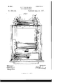
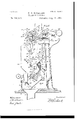
- Figure 1 is a front view of one form of this improved weighingmachine, With parts thereof in section and broken away more clearly to illustrate the same.
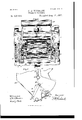
- Fig. 2 is a top or plan view thereof.
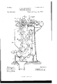
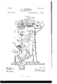
- Figs. 3, 4, 5, and 6 are right-hand side elevations of the machine, showing the operating mechanisms in various positions and with parts thereof in dotted lines and broken away 5 and
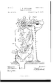
- Fig. 7 is a side elevation of the lower part of the load-receiver and illustrates the action of one closer relativelyto the other in shutting.
- the principal improvements of this weighing-machine relate to the closer mechanism and regulator mechanism, each provided with or embodying means whereby it is secured or locked against operation except at predetermined periods,whereby the regulator mechanism is locked against movement until the operation of the closer mechanism to discharge the load and which locking of the regulator mechanism prevents the improper actuation of the supply-valve mechanism, and whereby the closer mechanism is likewise locked to prevent the discharge of the load-receiver until the same has received its proper load-supply and the supply-valve mechanism has completely out off the supply therefrom, so that said mechanisms cannot be tampered with or prematurely actuated either to out off the supply of material to the load-receiver or to discharge a part of the load independently of the whole load.
- closer mechanism (designated in a general way by A;) means (designated in a general way by B) for locking the same closed or shut and embodying supplemental locking means (designated generally by 0) whereby the premature operation of the closer mechanism is positively prevented; regulator means, (designated in a general way by D,) and means (designated in a general way by E) for locking the regulator mechanism against premature operation, and which locking means is shown operative to unlock the regulator means by the closer meehanismand only after the same is unlocked, whereby such regulator mechanism is shown operable only by means of the discharging load from the receptacle after the opening of such closer mechanism.
- the framework for carrying the operative parts of the machine may be of any suitable and desired construction and form, but is herein shown preferably comprising two side frames 2 and 3, joined at the top by a top plate l, carrying in aterial-supply means,such as a chute 5, and connected and supported at the bottom by a base (3, shown provided with a bin 7, having an outlet or spout 8, and in which bin the regulatorhereinafter described works.
- the load receiver or receptacle shown in this instance as a bucket and designated generally by 200, may be of any desired form and construction, but is herein illustrated as preferably of the single-chambered type or class and provided with a discharge opening or spout 9, adapted to be closed by suitable mechanism hereinafter described.
- the loadreceivcr is supported on or carried for move ment by beam mechanism, shown herein'comprising a scale-beam 100, supported on the framework by suitable bearings, which are illustrated as t -shaped bearings, comprisin a pair of knife-edge pivots 10 and a pair of V- shaped bearing members 12, in which said pivots work; and in this form of apparatus the pivots are carried by a shaft 11 of the beam, while the bearin g members are shown carried by the top plate 4: of the framework in the rear of the supply-chute.
- This scalebeam 100 comprises a pair of supporting-arms 13 and let, having bearing-pivots 15 at their outer ends and shown engaging V-shaped bearing members 15, carried by hangers 17, secured to the load-receiver.
- a pair of weightsupporting arms 18 and 19 Extending rearwardly of the supportingarms 13 and 14 is a pair of weightsupporting arms 18 and 19, carrying a suitable counterbalance-weight 150, shown herein as rigid therewith, although any other disposition and character of weight might be used.
- the beam mechanism is provided with a supplemental adjustable weight 155, carried by a supporting member, such as a rod 156, disposed intermediate the weight-carrying arms 18 and 19, and on which said supplemental weight is adjustable toward and from the bearings and the main weight of the scale-beam, whereby on the adjustment thereof in a manner that will be readily understood a greater or less amount of material will be necessary to constitute the load.
- a supplemental adjustable weight 155 carried by a supporting member, such as a rod 156, disposed intermediate the weight-carrying arms 18 and 19, and on which said supplemental weight is adjustable toward and from the bearings and the main weight of the scale-beam, whereby on the adjustment thereof in a manner that will be readily understood a greater or less amount of material will be necessary to constitute the load.
- valve mechanism for regulating the supply of material to the load-receiver comprehends in this form of machine a pair of valves, herein designated as the reducingvalve operative to reduce the supply of material to a drip-stream, and the other the cutoff valve, operative to completely cut off such drip-stream, and which valve mechanism is shown, for the purposes of this specification, as substantially similar to that illustrated in my patent above referred to-to wit, Patent No. 142,719, dated December 16, 1890and hence a general description of which is only deemed necessary.
- the reducing-valve 20 comprises a valve- .blade 21, having a pair of arms 22 and 23, pivotall y supported by bearin gs 2-1, carried by the supply-chute, said valve being provided with a suitable stop 25 for limiting the closing movement thereof.
- This valve is provided with an arm or lever 20, carried by a hub of one of said arms, as 22, and which arm 20 is provided with a reducing-cam 27 and a weight28, both formed thereon, so that in the construction shown the valve, its arms 22 and 23, the lever or arm 20, the reducingcam 27, and weight 28 are an integral structure, such reducing-cam 27 being in position to be operated by an arm 29, carried by the scale-beam, in a manner hereinafter set forth.
- the cut-off valve 30 is shown as a eoncaved valve-blade 31 and is carried by arms 32 and 33, pivotally supported by bearings 84 at one side of the supply-chute.
- One of the valve-arms, as 32, is shown extending above its pivot and has formed thereon in this structure a cut-off valve-cam 35 and a weight 36.
- This cam 35 has three working faces 87, 37, and 37, the face 37 thereof being used to maintain the valve open and while the reducingvalve is closing, the face 37 being employed during the poising period and being substantially coincident in extent with the poising movement of the beam, and the face 37" being used to cut off the drip.
- valve-actuator herein shown comprises a bearing or roll 38, carried by an actuatorarm 39, having a stud or shaft journaled in a bearing of one of the scale-beam load-receiver-supporting arms, as 13.
- a connector or connecting member +1 in the nature of a lever or red, the opposite end of which is shown articulated to a bifurcated member or link 13, which in turn is jointed at its opposite end to one of the scale-beam weight-supporting arms, as 1 9.
- a connector or connecting member Pivotally secured at its upper end to this link 43, at the point of its connection with the connector a1, is a connector or connecting member, likewise shown herein as a lever or rod 44, the lower end of which is pivotally secured to the regulator hereinafter described, whereby on the operation of such regulator the link L3 and connector 4-1 are actuated, after the manner of a togglcjoint, to shift the valve-actuator 38 into and out of its operative position, the pivotal connection between such link 1 and connector 41 being shown coincident with the pivotpoint of the scale-beam, whereby the movement of the beam has no effect to operate the actuator.
- the beam-arm 29 above referred to for actuating the reducing-valve is journaled by a stud 29 in a suitable bearing 29, formed on one of the load-rcceiver-supporting arms, as 11, of the scale-beam, and the outer end of said stud carries a short arm 45, to which is pivotally attached a connector or connecting member 46, having its opposite end pivoted to a link 47, preferably similar to the link 43, which in turn has its opposite end pivoted to one of the scale-beam weight-arms, as 18.
- This link 47 and connector 4E0 are pivotally secured at their pivotal point, which is likewise coincident with the pivotal point of the scale-beam, to an actuator connector or connectin g member, shown as a lever 44, which in turn is pivotally secured to the regulator.
- the closer mechanism (designated in a general way by A) in the preferred form thereof herein shown and described comprises a pair of closers, one of which, for the purposes of this specification, will be designated as the main or regulator or regulating closer, while the other will be designated as the valve-closer or supplemental closer.
- the main or regulator closer 50 in the form shown comprehends a closer plate or blade 51, provided at each end thereof with a relatively wide side plate or wall 52, a part there of overlapping the side walls of the load-re ceiver throughout the entire operation of said closer, whereby such walls form stream-directing means for the discharging load.
- This closer is pivotallysecured to the load-receiver adjacent to the lower part of the discharge opening or spout 9 for shiftable movement, and in the construction shown the closer blade or plate 51 thereof is so disposed relatively to its pivotal axis that it swings sidewise about such axis, said blade or plate being set radially thereto.
- the valve or supplemental closer 55 in the form shown comprises a concaved blade or plate 56, likewise provided with a pair of relatively wide side walls or plates 57, a part of which preferably overlaps the walls of the bucket throughout the entire operation of said closer.
- This closer is pivotally secured to the load-receiver at a point relatively remote from the outlet or discharge opening 9 of the same-as, for instance, at 64Jwhereby the closer blade or plate 56 swings concentrically to its axis.
- the outer edge of the supplemental-closer blade 56 is bent or curved to form a hookshaped flange 59 in position to engage a flange (30, formed on the load-receiver at the edge of the discharge opening or spout 9, and so form a material-guard whereby the escape of the material is prevented, especially when material of a semifluidity is being weighed.
- the rear wall of the load-receiver can serve as a stop for the end of the curved flange 59, to thereby limit the shutting action of the closers, if desired, or such shutting movement may be limited by the frictional engagement of the curved edge 58 of the supplemental closer with the blade 51 of the main closer.
- a connector such as a link 61
- a connector is shown pivotally secured to one of the side walls 57 of the closer 55, approximately at the point 62, the opposite end of said link being pivotally secured to the regulator-closer approximately at the point 63, whereby the weight of the m aterial,aotin g on the regulatoreloser, swings the same open, and which opening movement opens, by means of the link 61, the supplemental closer, the weight of such supplemental closer,when open, being carried directly by the pivotal point (34: of the regulator-closer, in approximate alinement with which is the pivotal point 63 of the link 61, when such closers are open,whereby comparatively little power is necessary to maintain the closers open to permit the discharge of the load-receiver, the shutting of such closers bein g accomplished after all the material has left the load-receiver by the gravity due either to the weight of
- the main closer regulates the shutting of both closers, as it acts as a retarder or regulator and is held open by the material discharging from the load-receiver, and hence does not commence to shut until all appreciable amount of such material has passed from said load-receiver, and that while the main closer opens the supplemental closer and regulates the shutting of the same it will be observed that in this structure the supplemental closer shuts such main closer, owing to its weight and its bearing engagement downward in the direction of its closing movement.
- main and supplemental locking means operable at the proper time on the de scent of theload-reeeiver to permit the closers to open; and in the preferred form thereof herein shown and described the main locking means (designated in a general way by 13) comprises a locker, shown in the nature of a latch-lever 65 pivotally secured to the loadreceiver and provided with a catch 06 in position to engage a stop-arm 67, carried by the supplemental closer 55, the downward movement of such lever being limited by a stop or ICC pin 08.
- This locker has its free end in po sition to engage an actuator, shown in the nature of a pin 60, carried by the regulatorconnector 44, whereby on the descent of the load-receiver said locker will engage such pin 69 and be raised to permit the passage of the stop-arm G7, and thereby the opening of the closers by the weight of the material in the load-receiver.
- an actuator shown in the nature of a pin 60, carried by the regulatorconnector 44
- sup plemental locking means (designated in a general way by C) is provided, and which in this form of machine comprehends mechanism operable to lock said latch-lever 65 against movement, except when the load-receiver deseends by the weight of its full load, and in one preferred form thereof shown comprises a pivotally-disposed locker, illustrated herein as a sector-stop 7 0, carried by the load-receiver, and therefore movable therewith, and provided with a curved locking-face 7 2, in engagement with a stop-arm 71, carried by said latclrlever 05.
- a pivotally-disposed locker illustrated herein as a sector-stop 7 0, carried by the load-receiver, and therefore movable therewith, and provided with a curved locking-face 7 2, in engagement with a stop-arm 71, carried by said latclrlever 05.
- This locker '70 is provided with an arm 73, pivotally connected by a connector or link 7 4: with the connector 44, whereby said locker 7 O is operable both on the descent and ascent of the bucket, and also on the movement of said connector 44, in the manner and for the purpose hereinafter set forth.
- the regulator mechanism (designated in a general way by D) in the preferred form thereof herein shown and described comprises a regulator, shown herein as a hopper 80, having an outlet or discharge opening 81 at its front end intermediate the ends of a pair of inclined walls 82 and 83, the wall 82 servin g as a stream-directing wall, while the lower end of the front wall 83 is sufficiently remote from the free end of the stream-directing wall to permit the stream of material to pass without crowding the same as it leaves the hopper.
- a regulator shown herein as a hopper 80, having an outlet or discharge opening 81 at its front end intermediate the ends of a pair of inclined walls 82 and 83, the wall 82 servin g as a stream-directing wall, while the lower end of the front wall 83 is sufficiently remote from the free end of the stream-directing wall to permit the stream of material to pass without crowding the same as it leaves the hopper.
- This regulator hopper is shown herein pivotally secured for movement at the extreme lower end of the wall 82 to the side walls of the bin 7, whereby it is in position beneath the discharge-openin g of the load-receiver to receive theload therefrom, such load being delivered on the directing-wall of the hopper at a point relatively remote from its pivotal point, and whereby the outflowing stream offers no resistance to the movement of the regulator at the point of discharge thereof.
- An adjustable counterbalancingweight is carried at the front side of this hopper by an arm 85, whereby said hopper is held in its normal inoperative position.
- the connector-levers 44: and 44: are to the rear side of the hopper, or at that side thereof opposite the counterbalancingweight.
- the hopper outlet or discharge opening 81 is shown slightly smaller than the spout 9, as is the usual ease, and, if desired, such dischargeopening may be regulated by an adjustable closer or door Sb, secured in any desired manner to the front wall.
- the ascent and descent of the regulator-hopper is limited by a pair of stops 87 and 88, carried in position by one of the walls of the bin for this purpose.
- suitable locking mechanism herein shown as interlocking means and designated in ageneral way by E, is provided to prevent the operation of the regulator, except in the proper way and at a predetermined time, by and through the operation of a part of the weighin g-machine, and in the preferred form thereof herein shown and described this locking mechanism comprises a locker 90, having a locking part 91, and which locker is shown operatively connected with the closers, whereby the regulator is only operable after the opening of such closers.
- this locker 90 is shiftable relatively to the loadreceiver into position to engage a coacting arm 92, secured to the lower end of the arm 40, whereby such arm 40, connector 41, link 43, and connector 44 to a certain extent, in the construct-ion shown, constitute a part of the regulator-locking means, as well as the means for actuating the cut-off valve hereinafter described.
- This locker 90 is shown provided with a weight 93, carried by a projecting arm 94, and which locker is pivotally carried by a relatively short lever 95, which in turn is pivotally secured to the load-receiver and also to a connector or link 96, the opposite end of which is articulated to the supplemental closer in such position that the opening of such closer will actuate the locker to release the coactin g arm 92, and thus permit the operation of the regulator, which will be more particularly set forth in connection with the following operation: The regulator-hopper being in its normal inoperative position, the load-receiver raised, and the valves open and held in such position by the beam-arm 29 and the actuator 39, thematerial is permitted to flow into such load-receiver until the same is nearly loaded.
- the load-receiver descends to its poising-point, which allows the reducing-valve to close by carrying the beam-arm 29 away from engagement with the reducing-cam 27, and thereby reduce the flow of material to a drip-stream, the cutoff valve, however, being still held open by the actuator-arm roll 38, engaging the camface 37.
- the load-receiver still further descends, and the cut-off valve is permitted to close as the actuator-roll 38 is moved into position beneath the cam-face 37.
- the supplemental locker has been carried into position to permit the main locker (35 to be raised by the actuator-pin 69, and thus unlock the closers, which are immediately swung open by the weight of the load in the manner hereinbefore set forth.
- the open ing of the closers operates the regulatorlocker to shift the same away from the coacting arm 92 and permit the regulator to descend in the usual manner at the proper time.
- This descent of the regulator acts on the toggle connections formed by the links 43 and 47 with their respective connections 41 and 46 to draw the same downward from their neutral positions, and thus to shift the valve-actuators 29 and 39 into their inoperative positions, Fig. (I, and allow the weight of the cutoff valve 30 to throw fully over, and thus hold the valve tightly closed.
- the arm 92 is shifted into position to permit the regulator-locker 90 to be actuated by the descent of its weight 93 and to again coact with said arm and thus again lock the regulator against movement.
- the regulator ascends to its normal position it shifts the supplemental locker 70 into position to again lock the latch-lever locker 05 against movement.
- I clai1n- 1 The combination, with beam mechanism and with aload-receiver provided with a shiftable closer, of a regulator; and means carried by the loadreceiver and beam mechanism, for locking said regulator against premature operation.
- a regulator having a pair of inclined walls terminating in a discharge-opening and pivotally supported at the extreme lower edge of one of said inclined walls, whereby the outflowing stream offers no resistance to the movement of the regulatorat the point of discharge thereof.
- a weighing-machine the combination, with a load-receiver, of a supply-valve; actuating means for said valve; a regulator; and a reeiprocatory connector secured to said regulatorand operatively connected with said valve-actuatin g means, and operative to carry said valve-aetuatin g means into its ineffective position and thereby permit the valve to close on the descending movement of said connector sim ultaneously with the descending move ment of said regulator, and to carry said valve-actuating means into its effective position, thereby to open said valve on the ascent.
- a pair of closers pivotally secured to said load-receiver, and coupled together for simultaneous movement, and comprising a main or regulator closer radially disposed relatively to its pivotal axis, and a supplemental or valve closer concentrically disposed relatively to its pivotal axis, said regulator-closer being constructed and operable to open the supplemental closer and regulate the shutting of both of said closers, and said valve-closer being constructed and operable to shut said regulator-closer on its own closingmovement,
- said regulator closer also being constructed and timed to have, during the latter part of its closing operation, a relatively slow movement as compared with the movement of the valve-closer, whereby said regulator closer is scraped or cleaned free of material.
- the combination, with a load-receiver having closer mechanism comprehending a pair of shiftable closers pivotally secured thereto and comprising blades or plates, one radially disposed relatively to its axis and the other concentrically disposed relatively to its axis; of locking means in operative engagement with one of said closers and operable to maintain both of said closers shut; and supplemental locking means for maintaining the main locking means against premature operation.
- a load-receiver having closer mechanism comprehending a pair of shittable closers pivotally secured thereto and comprising blades or plates, one radially disposed relatir ely to its axis, and the other concentrically disposed relatively to its axis; regulator mechanism; main locking means carried by said load-receiver and in engagement with said closer mechanism, for maintaining the same shut; and supplemental locking means also carried by said load-receiver, for maintaining the main locking means against premature operation and in engagement with said regulator mechanism for operation thereby.
Landscapes
- Physics & Mathematics (AREA)
- General Physics & Mathematics (AREA)
- Filling Or Emptying Of Bunkers, Hoppers, And Tanks (AREA)
Description
(No Model.) P. HI RIGHARDS. 6 SheetsSheet 1.
WEIGHING MACHINE.
No. 589,302. Patented Aug. 31,1897.
Witnesses: lnvfinior Kilt/W /W .M
TH: NORRIS PEYER$ co FHOTD-LITHQ. wasumsrcm a. 4:.
6 SheetsSheet 2.
' (No Model.)
I. H. RICHARDS.
WEIGHING MACHINE. I No. 589,302. Patented Aug. 31,1897.
Wiinesses: Inventor.
(No Model.) 1 6 SheetsSheet 3. P. H. RICHARDS.
WEIGHING MACHINE.
No. 589,302. Patented Aug; 31,1897.
Witnesses. 3 Invenior/ fiwaww MUQM r m: norms runs 00, Purlmumo. wnmncm n r.
(No Model.) 6 SheetsSheet 4.
F. H. RICHARDS.
WEIGHING MACHINE.
No. 589,302. Patented Aug. 81,1897.
Witnesses, Inventor. WW M AM/z mr. annals vUEns cov PHOTO-LITNO WASwmmm u (No Model.) 6 Sheets-Sheet 5.
F. H. RICHARDS.
WEIGHING MACHINE.
No. 589,302. Patented Aug. 31,1897.
Ji W %x Km A \x Wit/2 6 $868; In ueniarx (No Model.) 6 SheetsSheet 6,
P. H. RICHARDS. WEIGHING MACHINE.
No. 589,302. Patented Aug. 31,1897.
Witnesses: jflvewior m: mmms wzrzns co, vHoTo-umo. wAsumbToN, o c
UNITED STATES PATENT OFFICE,
FRANCIS H. RICHARDS, O F HARTFORD, CONNECTCUT.
WEIGHING-MACHIVNE.
SPEGIFICAIION forming part of Letters Patent No. 589,302, dated August 31, 1897.
Application filed January 8, 1897. Serial No. 618,458. (No model.)
T0 all whom it may concern:
Be itknown that I, FRANCIS H. RICHARDS, a citizen of the United States, residing at Hartford, in the county of Hartford and State of Connecticut, have invented certain new and useful Improvements in lVeighing-Machines, of which the following is a specification.
This invention relates to weighingmachines, the object thereof being to provide weighing mechanism comprehending, among other improvements, improved closer mechanism and regulator mechanism having or embodying improved means whereby said mechanisms are secured or locked against movement, except at predetermined periods, in the operation of the machine.
In the drawings accompanying and forming part of this specification, Figure 1 is a front view of one form of this improved weighingmachine, With parts thereof in section and broken away more clearly to illustrate the same. Fig. 2 is a top or plan view thereof. Figs. 3, 4, 5, and 6 are right-hand side elevations of the machine, showing the operating mechanisms in various positions and with parts thereof in dotted lines and broken away 5 and Fig. 7 is a side elevation of the lower part of the load-receiver and illustrates the action of one closer relativelyto the other in shutting.
Similar characters designate like parts in all the figures of the drawings.
In a general way the principal improvements of this weighing-machine relate to the closer mechanism and regulator mechanism, each provided with or embodying means whereby it is secured or locked against operation except at predetermined periods,whereby the regulator mechanism is locked against movement until the operation of the closer mechanism to discharge the load and which locking of the regulator mechanism prevents the improper actuation of the supply-valve mechanism, and whereby the closer mechanism is likewise locked to prevent the discharge of the load-receiver until the same has received its proper load-supply and the supply-valve mechanism has completely out off the supply therefrom, so that said mechanisms cannot be tampered with or prematurely actuated either to out off the supply of material to the load-receiver or to discharge a part of the load independently of the whole load.
As a preface to a further description of this improved weighing apparatus it will be understood that the various parts of the machine ean be more or less modified without departing from the general scope of the invention and that the improved closer mechanism and regulator mechanism, with their accompanying locking means, may be employed with other valve mechanism or used independentlyof each other with various regulator or closer mechanisms, as the case may be, whereby they will effectively operate in a manner substantially similar to that herein set forth and shown.
This improved weighing-machine comprebends in a general way a load-receiver, beam mechanism for supporting the same,and valve mechanism for regulating the supply of material to said receptacle, all of which parts may or may not be substantially similar to those heretofore patented by me in various previous patents, to one of which only is reference herein deemed necessary-to wit, Patent No. M2,?l0, dated December 16, 1890; closer mechanism, (designated in a general way by A;) means (designated in a general way by B) for locking the same closed or shut and embodying supplemental locking means (designated generally by 0) whereby the premature operation of the closer mechanism is positively prevented; regulator means, (designated in a general way by D,) and means (designated in a general way by E) for locking the regulator mechanism against premature operation, and which locking means is shown operative to unlock the regulator means by the closer meehanismand only after the same is unlocked, whereby such regulator mechanism is shown operable only by means of the discharging load from the receptacle after the opening of such closer mechanism.
The framework for carrying the operative parts of the machine may be of any suitable and desired construction and form, but is herein shown preferably comprising two side frames 2 and 3, joined at the top by a top plate l, carrying in aterial-supply means,such as a chute 5, and connected and supported at the bottom by a base (3, shown provided with a bin 7, having an outlet or spout 8, and in which bin the regulatorhereinafter described works. This bin prevents overflow of the material should the same get packed or stuck in the discharge opening or spout 8 of the same' The load receiver or receptacle, shown in this instance as a bucket and designated generally by 200, may be of any desired form and construction, but is herein illustrated as preferably of the single-chambered type or class and provided with a discharge opening or spout 9, adapted to be closed by suitable mechanism hereinafter described. The loadreceivcr is supported on or carried for move ment by beam mechanism, shown herein'comprising a scale-beam 100, supported on the framework by suitable bearings, which are illustrated as t -shaped bearings, comprisin a pair of knife-edge pivots 10 and a pair of V- shaped bearing members 12, in which said pivots work; and in this form of apparatus the pivots are carried by a shaft 11 of the beam, while the bearin g members are shown carried by the top plate 4: of the framework in the rear of the supply-chute. This scalebeam 100 comprises a pair of supporting-arms 13 and let, having bearing-pivots 15 at their outer ends and shown engaging V-shaped bearing members 15, carried by hangers 17, secured to the load-receiver.
Extending rearwardly of the supportingarms 13 and 14 is a pair of weightsupporting arms 18 and 19, carrying a suitable counterbalance-weight 150, shown herein as rigid therewith, although any other disposition and character of weight might be used.
To counterbalance the load-receiver for different weights of loads, the beam mechanism is provided with a supplemental adjustable weight 155, carried by a supporting member, such as a rod 156, disposed intermediate the weight-carrying arms 18 and 19, and on which said supplemental weight is adjustable toward and from the bearings and the main weight of the scale-beam, whereby on the adjustment thereof in a manner that will be readily understood a greater or less amount of material will be necessary to constitute the load.
The valve mechanism for regulating the supply of material to the load-receiver comprehends in this form of machine a pair of valves, herein designated as the reducingvalve operative to reduce the supply of material to a drip-stream, and the other the cutoff valve, operative to completely cut off such drip-stream, and which valve mechanism is shown, for the purposes of this specification, as substantially similar to that illustrated in my patent above referred to-to wit, Patent No. 142,719, dated December 16, 1890and hence a general description of which is only deemed necessary.
The reducing-valve 20 comprises a valve- .blade 21, having a pair of arms 22 and 23, pivotall y supported by bearin gs 2-1, carried by the supply-chute, said valve being provided with a suitable stop 25 for limiting the closing movement thereof. This valve is provided with an arm or lever 20, carried by a hub of one of said arms, as 22, and which arm 20 is provided with a reducing-cam 27 and a weight28, both formed thereon, so that in the construction shown the valve, its arms 22 and 23, the lever or arm 20, the reducingcam 27, and weight 28 are an integral structure, such reducing-cam 27 being in position to be operated by an arm 29, carried by the scale-beam, in a manner hereinafter set forth.
The cut-off valve 30 is shown as a eoncaved valve-blade 31 and is carried by arms 32 and 33, pivotally supported by bearings 84 at one side of the supply-chute. One of the valve-arms, as 32, is shown extending above its pivot and has formed thereon in this structure a cut-off valve-cam 35 and a weight 36. This cam 35 has three working faces 87, 37, and 37, the face 37 thereof being used to maintain the valve open and while the reducingvalve is closing, the face 37 being employed during the poising period and being substantially coincident in extent with the poising movement of the beam, and the face 37" being used to cut off the drip. This cam 35, similar to the cam 27 of the reducing-valve, is set beyond the end of the valve, whereby space is obtained for the working of the valve-actuator across the line of the valveaxis and outside of said valve and its pivots. The valve-actuator herein shown comprises a bearing or roll 38, carried by an actuatorarm 39, having a stud or shaft journaled in a bearing of one of the scale-beam load-receiver-supporting arms, as 13. Iivotally secured to an arm 10, disposed at the opposite end of this actuator-arm shaft, is a connector or connecting member +1, in the nature of a lever or red, the opposite end of which is shown articulated to a bifurcated member or link 13, which in turn is jointed at its opposite end to one of the scale-beam weight-supporting arms, as 1 9. Pivotally secured at its upper end to this link 43, at the point of its connection with the connector a1, is a connector or connecting member, likewise shown herein as a lever or rod 44, the lower end of which is pivotally secured to the regulator hereinafter described, whereby on the operation of such regulator the link L3 and connector 4-1 are actuated, after the manner of a togglcjoint, to shift the valve-actuator 38 into and out of its operative position, the pivotal connection between such link 1 and connector 41 being shown coincident with the pivotpoint of the scale-beam, whereby the movement of the beam has no effect to operate the actuator.
The beam-arm 29 above referred to for actuating the reducing-valve is journaled by a stud 29 in a suitable bearing 29, formed on one of the load-rcceiver-supporting arms, as 11, of the scale-beam, and the outer end of said stud carries a short arm 45, to which is pivotally attached a connector or connecting member 46, having its opposite end pivoted to a link 47, preferably similar to the link 43, which in turn has its opposite end pivoted to one of the scale-beam weight-arms, as 18. This link 47 and connector 4E0 are pivotally secured at their pivotal point, which is likewise coincident with the pivotal point of the scale-beam, to an actuator connector or connectin g member, shown as a lever 44, which in turn is pivotally secured to the regulator.
The closer mechanism (designated in a general way by A) in the preferred form thereof herein shown and described comprises a pair of closers, one of which, for the purposes of this specification, will be designated as the main or regulator or regulating closer, while the other will be designated as the valve-closer or supplemental closer.
The main or regulator closer 50 in the form shown comprehends a closer plate or blade 51, provided at each end thereof with a relatively wide side plate or wall 52, a part there of overlapping the side walls of the load-re ceiver throughout the entire operation of said closer, whereby such walls form stream-directing means for the discharging load. This closer is pivotallysecured to the load-receiver adjacent to the lower part of the discharge opening or spout 9 for shiftable movement, and in the construction shown the closer blade or plate 51 thereof is so disposed relatively to its pivotal axis that it swings sidewise about such axis, said blade or plate being set radially thereto.
The valve or supplemental closer 55 in the form shown comprises a concaved blade or plate 56, likewise provided with a pair of relatively wide side walls or plates 57, a part of which preferably overlaps the walls of the bucket throughout the entire operation of said closer. This closer is pivotally secured to the load-receiver at a point relatively remote from the outlet or discharge opening 9 of the same-as, for instance, at 64Jwhereby the closer blade or plate 56 swings concentrically to its axis. These closers are so disposed with relation to each other that when shut a part of the side walls of the supplemental closer will be overlapped by the side walls of the regulator-closer, the inner edge 58 of the supplemental closer blade or plate 56 being bent or curved to engage the regulator closer blade or plate 51, whereby when in action, owing to the relatively slow closing movement of one closer relatively to the other, Fig. 7, the supplemental closer scrapes or cleans the regulator-closer at and adjacent to that part thereof where such closers form the joint, and thus prevents any sticking or caking of the material at such place, which would prevent in a short time the tight shutting of the closers and thus permit the material to escape.
The outer edge of the supplemental-closer blade 56 is bent or curved to form a hookshaped flange 59 in position to engage a flange (30, formed on the load-receiver at the edge of the discharge opening or spout 9, and so form a material-guard whereby the escape of the material is prevented, especially when material of a semifluidity is being weighed. The rear wall of the load-receiver can serve as a stop for the end of the curved flange 59, to thereby limit the shutting action of the closers, if desired, or such shutting movement may be limited by the frictional engagement of the curved edge 58 of the supplemental closer with the blade 51 of the main closer. These closers in the construction shown are connected together,whereby they are operable simultaneously, theone by the other, and for this purpose a connector, such as a link 61, is shown pivotally secured to one of the side walls 57 of the closer 55, approximately at the point 62, the opposite end of said link being pivotally secured to the regulator-closer approximately at the point 63, whereby the weight of the m aterial,aotin g on the regulatoreloser, swings the same open, and which opening movement opens, by means of the link 61, the supplemental closer, the weight of such supplemental closer,when open, being carried directly by the pivotal point (34: of the regulator-closer, in approximate alinement with which is the pivotal point 63 of the link 61, when such closers are open,whereby comparatively little power is necessary to maintain the closers open to permit the discharge of the load-receiver, the shutting of such closers bein g accomplished after all the material has left the load-receiver by the gravity due either to the weight of one of the closers or by the addition of a counterbalanee-weight to one or both of the same,as may be desired. Thus it will be seen that the main closer regulates the shutting of both closers, as it acts as a retarder or regulator and is held open by the material discharging from the load-receiver, and hence does not commence to shut until all appreciable amount of such material has passed from said load-receiver, and that while the main closer opens the supplemental closer and regulates the shutting of the same it will be observed that in this structure the supplemental closer shuts such main closer, owing to its weight and its bearing engagement downward in the direction of its closing movement.
In order to lock the closers shut while the valves are open and the load is being made, suit-able mechanism is provided for this purpose, and in the form shown preferably comprehends main and supplemental locking means operable at the proper time on the de scent of theload-reeeiver to permit the closers to open; and in the preferred form thereof herein shown and described the main locking means (designated in a general way by 13) comprises a locker, shown in the nature of a latch-lever 65 pivotally secured to the loadreceiver and provided with a catch 06 in position to engage a stop-arm 67, carried by the supplemental closer 55, the downward movement of such lever being limited by a stop or ICC pin 08. This locker has its free end in po sition to engage an actuator, shown in the nature of a pin 60, carried by the regulatorconnector 44, whereby on the descent of the load-receiver said locker will engage such pin 69 and be raised to permit the passage of the stop-arm G7, and thereby the opening of the closers by the weight of the material in the load-receiver. To prevent the premature opening of the closers by lifting this latchlever 65, either accidentallyor otherwise, sup plemental locking means (designated in a general way by C) is provided, and which in this form of machine comprehends mechanism operable to lock said latch-lever 65 against movement, except when the load-receiver deseends by the weight of its full load, and in one preferred form thereof shown comprises a pivotally-disposed locker, illustrated herein as a sector-stop 7 0, carried by the load-receiver, and therefore movable therewith, and provided with a curved locking-face 7 2, in engagement with a stop-arm 71, carried by said latclrlever 05. This locker '70 is provided with an arm 73, pivotally connected by a connector or link 7 4: with the connector 44, whereby said locker 7 O is operable both on the descent and ascent of the bucket, and also on the movement of said connector 44, in the manner and for the purpose hereinafter set forth.
From the foregoing it will be seen that until the descent of the load-receiver with its proper load the latch-lever cannot be raised either accidentally or otherwise. 0n the descent of the load-receiver, however, the locker is swung, in this construction, outwardly through the medium of its arm 73 and link '74:, as the regulator 44 remains stationary,
the curved locking-face 72 of said locker,
however, remaining in engagement with the stop-arm 71 of the latch-lever 65 until such latch-lever has nearly reached the pin 09, at which time the further descent of the load receiver carries said sector-locker '70 into such position that the stop-arm 71 of said latch-lever 65 can pass the side a thereof, ig. 5, whereby the latch-lever is raised by the actuator-pin 69, the raising of such latchlever thus unlocking the closers and permitting the same to open by the weight of the load in the load-receiver.
In the construction shown on the descent of the regulator D it draws downward the actuator-pin 69, and thus permits the descent of the latch-lever 65. hen the load-receiver reascends in the usual manner after a discharge of a portion of its material, the locker will be swung into position to again engage the stoparm 71 of the latch-lever, and hence in order to permit the passage of the closer-arm (i7 beneath the locker-catch 66 and thereby relock the closers it is necessary, in this particular structure, that the locker 70 be swung out of engagement with said locker 65 to permit the raising of the same, this being accomplished by the descent of the regulator, which thus oscillates said locker 70 inwardly and permits the upward movement of the latch-lever stop-arm '71 past the side 1) thereof, Fig. 6, whereby said locker latch-lever is free to be raised by the closer-arm 67 as the same passes beneath the catch (30 thereof, the locker 70 being moved into its normal locking position on the return or ascent of the regulator. From the foregoing it will thus be seen that the locker 70 remains in looking engagement with the locker stop-arm 71 until the locker (35 is in position to be raised by the actuator-pin on the descent of the load-receiver, so that the premature actuation of such locker (i5 is thus positively prevented.
The regulator mechanism (designated in a general way by D) in the preferred form thereof herein shown and described comprises a regulator, shown herein as a hopper 80, having an outlet or discharge opening 81 at its front end intermediate the ends of a pair of inclined walls 82 and 83, the wall 82 servin g as a stream-directing wall, while the lower end of the front wall 83 is sufficiently remote from the free end of the stream-directing wall to permit the stream of material to pass without crowding the same as it leaves the hopper. This regulator hopper is shown herein pivotally secured for movement at the extreme lower end of the wall 82 to the side walls of the bin 7, whereby it is in position beneath the discharge-openin g of the load-receiver to receive theload therefrom, such load being delivered on the directing-wall of the hopper at a point relatively remote from its pivotal point, and whereby the outflowing stream offers no resistance to the movement of the regulator at the point of discharge thereof. An adjustable counterbalancingweight is carried at the front side of this hopper by an arm 85, whereby said hopper is held in its normal inoperative position. To the rear side of the hopper, or at that side thereof opposite the counterbalancingweight, the connector-levers 44: and 44: are
pivotally secured, whereby on the downward movement of the hopper the actuator-pin 69 is drawn away from the latch-lever 65. The hopper outlet or discharge opening 81 is shown slightly smaller than the spout 9, as is the usual ease, and, if desired, such dischargeopening may be regulated by an adjustable closer or door Sb, secured in any desired manner to the front wall. The ascent and descent of the regulator-hopper is limited by a pair of stops 87 and 88, carried in position by one of the walls of the bin for this purpose.
As it is possible in some constructions of weighing machines employing a regulatorhopper to tamper with the operation of the entire machine through the medium of such hopper by the foot or otherwise, and thus cut off the flow of material to the bucket, suitable locking mechanism, herein shown as interlocking means and designated in ageneral way by E, is provided to prevent the operation of the regulator, except in the proper way and at a predetermined time, by and through the operation of a part of the weighin g-machine, and in the preferred form thereof herein shown and described this locking mechanism comprises a locker 90, having a locking part 91, and which locker is shown operatively connected with the closers, whereby the regulator is only operable after the opening of such closers. In the form illustrated this locker 90 is shiftable relatively to the loadreceiver into position to engage a coacting arm 92, secured to the lower end of the arm 40, whereby such arm 40, connector 41, link 43, and connector 44 to a certain extent, in the construct-ion shown, constitute a part of the regulator-locking means, as well as the means for actuating the cut-off valve hereinafter described. This locker 90 is shown provided with a weight 93, carried by a projecting arm 94, and which locker is pivotally carried by a relatively short lever 95, which in turn is pivotally secured to the load-receiver and also to a connector or link 96, the opposite end of which is articulated to the supplemental closer in such position that the opening of such closer will actuate the locker to release the coactin g arm 92, and thus permit the operation of the regulator, which will be more particularly set forth in connection with the following operation: The regulator-hopper being in its normal inoperative position, the load-receiver raised, and the valves open and held in such position by the beam-arm 29 and the actuator 39, thematerial is permitted to flow into such load-receiver until the same is nearly loaded. Then the major part of the load has been received by the load-receiver, it descends to its poising-point, which allows the reducing-valve to close by carrying the beam-arm 29 away from engagement with the reducing-cam 27, and thereby reduce the flow of material to a drip-stream, the cutoff valve, however, being still held open by the actuator-arm roll 38, engaging the camface 37. On the full load being madeup by the drip-stream the load-receiver still further descends, and the cut-off valve is permitted to close as the actuator-roll 38 is moved into position beneath the cam-face 37. At this time the supplemental locker has been carried into position to permit the main locker (35 to be raised by the actuator-pin 69, and thus unlock the closers, which are immediately swung open by the weight of the load in the manner hereinbefore set forth. The open ing of the closers operates the regulatorlocker to shift the same away from the coacting arm 92 and permit the regulator to descend in the usual manner at the proper time. This descent of the regulator acts on the toggle connections formed by the links 43 and 47 with their respective connections 41 and 46 to draw the same downward from their neutral positions, and thus to shift the valve- actuators 29 and 39 into their inoperative positions, Fig. (I, and allow the weight of the cutoff valve 30 to throw fully over, and thus hold the valve tightly closed.
hen all appreciable amount of material has passed from the bucket, the closers immediately shut in the manner heretofore set forth and throw the regulator-locker 90 into a position substantially similar to that shown by dotted lines in Fig. ('5, whereby it engages the outer end of the coactin g arm 92, and the locker-weight U3 is thus raised into position in readiness to shift the locker into its normal locking position, so that when the major portion of the discharged load has passed from the regulator-hopper said hopper gradually rises and moves the connectors 44 and 44 upward to open the valves 20 and 30 by mean of the toggle connections and beamarm 29 and actuator-arm 39, Fig. 3, in a manner that will be readily understood. As the actuator-arm 39 is moved forward to engage the working face 37 of the cam 35 the arm 92 is shifted into position to permit the regulator-locker 90 to be actuated by the descent of its weight 93 and to again coact with said arm and thus again lock the regulator against movement. As the regulator ascends to its normal position it shifts the supplemental locker 70 into position to again lock the latch-lever locker 05 against movement.
From the foregoing it will thus be seen that the closers cannot be opened until the descent of the bucket with its load and. that the regulator cannot be actuated until the opening of the closers, so that the premature operation of these parts, with the resultant operation of the weighing mechanism, is pre vented.
Having described my invention, I clai1n- 1. The combination, with beam mechanism and with aload-receiver provided with a shiftable closer, of a regulator; and means carried by the loadreceiver and beam mechanism, for locking said regulator against premature operation.
2. The combination,with beam m eehanism, of a load-receiver supported thereby and havinga shiftable closer; a regulator; and means operatively connected with the closer and carried by a load-receiver and beam mechanism, for locking the regulator against premature operation.
3. The combination, with weighing mechanism embodying a load-receiver provided with a shiftable closer, and with a regulator, of weighted locking mechanism operable to lock the regulator against premature operation and operatively connected with the closer, for operation thereby on the opening of the same to thereby unlock the regulator, said locking mechanism being operable, by its weight on the shutting of the closer, to relock such regulator.
4. The combination ,with beam mechanism, of a load-receiver having a shit'table closer; a regulator; and locking mechanism for looking said regulator against premature operation, and comprising a plurality of shiftable IIO members, one carried by the beam mechanism and connected with the regulator, and the other carried by the load-receiver.
5. The combination,with beam mechanism, of a load-receiver having a shiftable closer; a regulator; lockingmechanism for such regulator and comprehending a locker carried by the load-receiver and connected with the closer, whereby it is shiftable therewith, and levermechanism connected with the beam mechanism and regulator and embodying an arm adapted to be locked against movement, whereby the regulator is likewise locked against movement.
6. The combination,with beam mechanism, of a load-receiver having a shiftable closer; a supply-valve; a regulator; valve-actuating means connected with and operated by the regulator for opening said valve; and locking mechanism for said regulator, a part thereof operative with said valve-actuating means.
7. The combination,with beam mechanism, of a load-receiver having a shiftable closer; a supply-valve; a regulator-hopper; means operatively connected to the beam mechanism and hopper and operative to actuate said valve; and locking mechanism for said hopper, a part thereof operatively connected with the valve-actuating mechanism and a part thereof carried by the load-receiver and connected with the closerand shiftable therewith to unlock said hopper.
8. The combination,withacounterweighted scale-beam, and with a load-receiver having a shiftable closer, of reducing and cut-off valves; shiftable actuators for said valves; a regulator; means connecting said regulator with said actuators, whereby said actuators are operative by and with said regulator thereby to open said valves at the proper predetermined period; and locking mechanism for said regulator.
9. The eombinatiomwith a counterweighted scale-beam and with a load-receiver having a closer, of reducing and cut-off valves; shift able actuators, one for each valve; a regulator-hopper below said load-receiver; shifting devices connected with said hopper and with eachof said actuators; and locking mechanism for said regulator, comprising a plurality of interlocking members, one pivotally connected with one of said actuators and the other with the loadreceiver and closer and shiftable with said closer to unlock said regulator.
10. Ina weighing-machine, a regulator having a pair of inclined walls terminating in a discharge-opening and pivotally supported at the extreme lower edge of one of said inclined walls, whereby the outflowing stream offers no resistance to the movement of the regulatorat the point of discharge thereof.
11. In a weighing-machine, the combination, with a load-receiver, of a supply-valve; actuating means for said valve; a regulator; and a reeiprocatory connector secured to said regulatorand operatively connected with said valve-actuatin g means, and operative to carry said valve-aetuatin g means into its ineffective position and thereby permit the valve to close on the descending movement of said connector sim ultaneously with the descending move ment of said regulator, and to carry said valve-actuating means into its effective position, thereby to open said valve on the ascent.
of said connector simultaneously with the return or ascent of said regulator to its normal position.
12. The combination, with a load-receiver; of closers, each pivotally secured to said loadreceiver and comprising a pair of blades, one radially disposed relatively to its pivotal axis, and the other concentrically disposed relatively to its pivotal axis.
13. The combination, with a load-receiver; of shiftable closers pivotally secured thereto and having overlapping sides, and one embodying a blade radially disposed relatively to its pivotal axis, and the other a concave blade concentrically disposed relatively to its pivotal axis, the sides of said closers maintainin g a permanent overlapping engagement with the walls of said load-receiver, thereby forming stream-directing walls for the discharging material.
lt. The combination, with Weighing mechanism embody ing a load-receiver, of a main and a supplemental closer secured to said load-receiver and shiftable to discharge the load and coupled together for movement, said main closer being operative to open the supplemental closer and regulate the shutting of both of said closers; a regulator; and locking means for locking said regulator against premature operation and operatively connected with said regulator and directly connected with said supplemental closer, whereby it is operated thereby 011 the operation of the main closer.
15. The combination, with a load-receiver, of a pair of closers each pivotall y secured to said load-receiver and coupled together for simultaneous movement, one radially disposed relatively to its pivotal axis and the other concentrically disposed relatively to its pivotal axis, and one of said closers constructed and timed to have a relatively slow closing movement during the latter part of its operation as compared with the closing movement of its companion closer.
16. The combination, with a load-receiver,
of a pair of closers pivotally secured to said load-receiver, and coupled together for simultaneous movement, and comprising a main or regulator closer radially disposed relatively to its pivotal axis, and a supplemental or valve closer concentrically disposed relatively to its pivotal axis, said regulator-closer being constructed and operable to open the supplemental closer and regulate the shutting of both of said closers, and said valve-closer being constructed and operable to shut said regulator-closer on its own closingmovement,
and said regulator closer also being constructed and timed to have, during the latter part of its closing operation, a relatively slow movement as compared with the movement of the valve-closer, whereby said regulator closer is scraped or cleaned free of material.
17. The combination, with a load-receiver, of a pair of closers coupled together forsimultaneous movement and each comprising a blade or plate pivotally secured for shiftable movement relatively to said receiver and one having its blade radially disposed relatively to its axis and the other having its blade eoncentrically disposed relatively to its axis.
18. The combination, with beam mechanism, of a load-receiver; a regulator; and means carried by the load-receiver and beam mechanism, and connected with the regulator for locking said regulator against premature operation.
10. The combination, with a load-receiver; of a main closer and a supplemental closer, both pivotally secured thereto for shiftable movement and comprising a pair of blades or plates, one radially disposed relatively to its axis and the other concentrically disposed relatively to its axis; and a connector pivot ally secured to each of said closers, the pivotal point of the connector with the main closer being such that when said closers are open such pivotal point will be in approximate alineinent with the axis of said main closer, whereby comparatively little power is required to maintain such closers open.
20. The combination, with a load-receiver having a discharge opening or spout and a flange adjacent thereto, of a closer shiftably secured to said receiver and provided with a flange at its rear end extending around. said receiver-flange and thereby forming a guard to prevent the discharge of material from said receiver at this point.
21. The combination, with a load-receiver having a discharge opening or spout and a flange adjacent thereto, of a main closer shiftably secu red to said load-receiver; and a supplemental closer also shiftably secured thereto and comprising a concave blade having a curved rear end extending around said flange and thereby forming a guard to prevent the discharge of material at this point.
22. The combination, with a load-receiver having a flange adjacent its discharge-opening, of a main closer pivotally secured to said receiver and provided with a pair of relatively wide sides and a blade radially disposed relatively to the axis of said closer; a supplemental closer also provided with a pair of relatively wide sides overlapped by the sides of said main closer and a concave blade concentrically disposed relatively to the axis of said closer and having a curved flange at its rear end coacting with the flange on the load-receiver; and a connector pivotally secured to each closer, its pivotal point with the main closer being such that when said closers are open such pivotal point will be in approximate alinement with the pivotal axis of said closer.
The combination, with a load-receiver having a shiftable closer, of regulator mechanism; main locking means for securing said closer in a shut position; and supplemental locking means operative to lock said main locking means against premature operation and connected to, and operable with, said regulator mechanism.
at. The combination, with a load-receiver having a shiftable closer, of regulator mechanism; main locking means operative to lock said closer shut; and supplemental locking means operative to lock said main closerlocking means against premature operation and operatively connected with the receptacle and regulator mechanism,whereby, on the movement of said receptacle and regulator mechanism, said supplemental locking means will lock and unlock said main locking means.
25. The combination, with weighing mechanism embodying a load-receiver provided with a shiftable closer, of a main locker for maintaining the same shut; and a supplemental locker operative to secure said main locker against premature operation andhavin g a reciprocatory and oscillatory movement, and oscillatory on its reciprocatory movement into position to lock and unlock said main locker.
2G. The combination, with a reciprocatory load-receiver having a shiftable closer, and with a regulator; of an oscillatory main locker carried by the load-receiver, for maintaining said closer shut; and an oscillatory locker connected with the regulator and operable, on the descent and ascent of said load-receiver and regulator, in a plane transversely of the plane of movement of such reciprocatory load-receiver, to lock and unlock said main locker.
27. The combination, with a load-receiver having ashiftable closer, of a regulator main locking means operative to loci; said closer shut; and supplemental locking means operative in two directions 011 the movement of the load-receiver and also operative in two directions on the movement of the regulator, to lock and unlock said main locking means.
28. The combination, with a load-receiver having a shiftable closer, of regulator mechanism; main locking means for locking said closer shut; and supplemental locking means carried by the load-1' eceiver and operatively connected with the regulator mechanism, for movement therewith, and operative to lock the main locking means against premature operation.
29. The combination, with a loadreceiver having a shiftable closer, of regulator mechanism a main locker carried by the load-receiver and operative to lock the closer shut and asupplemental locker also carried by, and movable with, the load-receiver and having movements in two intersecting planes and op eratively connected with the regulator mechanism for operation thereby.
30. The combination, with a load-receiver having a shiftable closer, of a supply-valve; means for actuating said valve; a regulator having a connector in engagement with the valve-actuating means; a main locker to lock the closer shut; and a supplemental locker to lock the main locker against premature movement, and connected with the regulator-conncctor for operation by said regulator.
31. The combination, with a load-receiver having a shiftable closer, of a supply-valve; means for actuating said valve; a regulatorhopper having a connector in engagement with the valveactuatin g means; a locker carried bythe load-receiver and operative to lock the closer shut; and a supplemental locker also carried by, and movable with, the loadrecciver and operative to lock the main locker against premature movement and connected with the connector of said regnlator-hopper, for operation by said hopper.
The combination, with a reciprocatm'y load-receiver having a shiftable closer, of a supply-valve; means foractuating said valve; a regulator having a connector in engagement with the valveactuatin'g means; main locking means comprising a latch-lever pivotally secured to the load-receiver and provided with a stop-arm supplemental locking means comprising an oscillatory member secured to the load-receiver and in position to engage said stop-arm; and a device connecting said oscil latory member with the regulator-connector.
33. The combination, with a load-receiver having a shiftable closer, of a supply-valve; means for actuating said valve; a regulator having a connector in engagement with said valve-actuating means; an actuator carried by said connector; a main locker carried by said load-receiver and operative by said connector-actuator to unlock said closer; and a supplemental locker also carried by said leadreceiver and operatively connected with the regulator-connector.
The combination, with beam mechanism, of a load-receiver supported thereby and having a shiftable closer; locking means for said closer; regulator mechanism; locking means for said regulator mechanism, and operative, on the opening of the closer, to unlock said regulator mechanism; and actuating means carried by said regulator mechanism and in position to unlock said closer-locking means.
35. The combination, with beam mechanism, of a load-receiver supported thereby-and having aplurality of shiftable closers coupled together for simultaneous movement; locking means for said closers; a regulator; and locking means for said regulator, and connected with one of the closers and operative, on the opening of said closers, to unlock said regulater.
236. The combination, with beam mechanism, ot a load-receiver supported thereby and having a shiftable closer; regulator mechanism; main locking means for said closer; supplemental locking means connected with the regulator mechanism, for locking the main locking means; and locking means for said regulator, and connected with the closer and operable, on the opening of said closer, to unlock said regulator.
37. The combination, with beam mechanism, of aload-receiver supported thereby and having apair of shit table closers; valve 1n echanism; a regulator-ho mer; meanstor actuating said valve mechanism, and operable by said hopper; main locking means for said closers; supplemental locking means for said main locking means, and connected to said load-receiverand hopper; and locking means for said hopper, and carried by said valve-actuating means and load-reeeiver and connected with one of said closers.
38. The combination, with a load-rceeiver having a pair of shiftable closers pivotally secured thereto and comprising blades or plates, one radially disposed relatively to its axis and the other concentrically disposed relatively to its axis; of locking means in operative en-. gagement with one of said closers and operable to lock both of said closers shut.
39. The combination, with a load-receiver having closer mechanism comprehending a pair of shiftable closers pivotally secured thereto and comprising blades or plates, one radially disposed relatively to its axis and the other concentrically disposed relatively to its axis; of locking means in operative engagement with one of said closers and operable to maintain both of said closers shut; and supplemental locking means for maintaining the main locking means against premature operation.
4.0. The combination, with a load-receiver having closer mechanism comprehending a pair of shittable closers pivotally secured thereto and comprising blades or plates, one radially disposed relatir ely to its axis, and the other concentrically disposed relatively to its axis; regulator mechanism; main locking means carried by said load-receiver and in engagement with said closer mechanism, for maintaining the same shut; and supplemental locking means also carried by said load-receiver, for maintaining the main locking means against premature operation and in engagement with said regulator mechanism for operation thereby.
4-1. The combination, with beam mechanism, of a load-receiver having a shittable closer supported thereby; a regulator disposed below said load-receiver; a supplyvalve; means for actuating said valve, said means being connected with said regulator for operation thereby; locking means for said regulator, comprehending an arm connected with said beam mechanism a Weighted locker shiftably secured to said load-receiver and a connector pivotally secured to said locker and closer.
FRANCIS H. RICHARDS.
Vitnesses:
FRED. J. DOLE, HEATH SUTHERLAND.
Publications (1)
| Publication Number | Publication Date |
|---|---|
| US589302A true US589302A (en) | 1897-08-31 |
Family
ID=2657965
Family Applications (1)
| Application Number | Title | Priority Date | Filing Date |
|---|---|---|---|
| US589302D Expired - Lifetime US589302A (en) | Weighing-machine |
Country Status (1)
| Country | Link |
|---|---|
| US (1) | US589302A (en) |
Cited By (1)
| Publication number | Priority date | Publication date | Assignee | Title |
|---|---|---|---|---|
| US2531303A (en) * | 1947-11-17 | 1950-11-21 | Elmer S Scott | Weighing apparatus |
-
0
- US US589302D patent/US589302A/en not_active Expired - Lifetime
Cited By (1)
| Publication number | Priority date | Publication date | Assignee | Title |
|---|---|---|---|---|
| US2531303A (en) * | 1947-11-17 | 1950-11-21 | Elmer S Scott | Weighing apparatus |
Similar Documents
| Publication | Publication Date | Title |
|---|---|---|
| US589302A (en) | Weighing-machine | |
| US631052A (en) | Weighing-machine. | |
| US560600A (en) | Weighing-machine | |
| US871630A (en) | Discharge-controlling mechanism for weighing-machines. | |
| US589282A (en) | Weighing-machine | |
| US442719A (en) | richards | |
| US607461A (en) | Automatic weighing-machine | |
| US560545A (en) | Weighing-machine | |
| US585970A (en) | Weighing-machine | |
| US624379A (en) | Weighing-machine | |
| US578158A (en) | Weighing-machine | |
| US442717A (en) | richards | |
| US600038A (en) | Weighing-machine | |
| US585979A (en) | Automatic weighing-machine | |
| US573420A (en) | Weighing apparatus | |
| US565229A (en) | Weighing-machine | |
| US559747A (en) | Weighing-machine | |
| US28262A (en) | Automatic grain-weighing machine | |
| US403988A (en) | H- cooley | |
| US589291A (en) | Weighing-machine | |
| US559214A (en) | Weighing-machine | |
| US447354A (en) | richards | |
| US607481A (en) | Automatic weighing-machine | |
| US548839A (en) | Automatic weighing-machine | |
| US570303A (en) | Weighing-machine |