US5890047A - Externally heated NFFR fuser - Google Patents
Externally heated NFFR fuser Download PDFInfo
- Publication number
- US5890047A US5890047A US09/004,758 US475898A US5890047A US 5890047 A US5890047 A US 5890047A US 475898 A US475898 A US 475898A US 5890047 A US5890047 A US 5890047A
- Authority
- US
- United States
- Prior art keywords
- belt
- nip
- pressure
- roll
- toner images
- Prior art date
- Legal status (The legal status is an assumption and is not a legal conclusion. Google has not performed a legal analysis and makes no representation as to the accuracy of the status listed.)
- Expired - Lifetime
Links
- 239000000758 substrate Substances 0.000 claims abstract description 12
- 230000003028 elevating effect Effects 0.000 claims abstract 3
- 238000000034 method Methods 0.000 claims description 11
- 238000010438 heat treatment Methods 0.000 description 21
- 239000000463 material Substances 0.000 description 18
- 229920001971 elastomer Polymers 0.000 description 11
- 239000003795 chemical substances by application Substances 0.000 description 8
- 239000002245 particle Substances 0.000 description 5
- 230000008569 process Effects 0.000 description 5
- 238000012546 transfer Methods 0.000 description 5
- 238000003825 pressing Methods 0.000 description 4
- 229920002379 silicone rubber Polymers 0.000 description 4
- 239000004945 silicone rubber Substances 0.000 description 4
- 230000007246 mechanism Effects 0.000 description 3
- 229910052751 metal Inorganic materials 0.000 description 3
- 239000002184 metal Substances 0.000 description 3
- 239000010453 quartz Substances 0.000 description 3
- VYPSYNLAJGMNEJ-UHFFFAOYSA-N silicon dioxide Inorganic materials O=[Si]=O VYPSYNLAJGMNEJ-UHFFFAOYSA-N 0.000 description 3
- PXHVJJICTQNCMI-UHFFFAOYSA-N Nickel Chemical compound [Ni] PXHVJJICTQNCMI-UHFFFAOYSA-N 0.000 description 2
- 229910000831 Steel Inorganic materials 0.000 description 2
- 229910052782 aluminium Inorganic materials 0.000 description 2
- XAGFODPZIPBFFR-UHFFFAOYSA-N aluminium Chemical class [Al] XAGFODPZIPBFFR-UHFFFAOYSA-N 0.000 description 2
- 238000013459 approach Methods 0.000 description 2
- 239000004020 conductor Substances 0.000 description 2
- 239000000356 contaminant Substances 0.000 description 2
- 230000000694 effects Effects 0.000 description 2
- 239000008187 granular material Substances 0.000 description 2
- 239000000843 powder Substances 0.000 description 2
- 239000010959 steel Substances 0.000 description 2
- VYZAMTAEIAYCRO-UHFFFAOYSA-N Chromium Chemical compound [Cr] VYZAMTAEIAYCRO-UHFFFAOYSA-N 0.000 description 1
- 229920002449 FKM Polymers 0.000 description 1
- 230000009471 action Effects 0.000 description 1
- 230000004888 barrier function Effects 0.000 description 1
- 230000015556 catabolic process Effects 0.000 description 1
- 239000011248 coating agent Substances 0.000 description 1
- 238000000576 coating method Methods 0.000 description 1
- 239000000470 constituent Substances 0.000 description 1
- 238000006731 degradation reaction Methods 0.000 description 1
- 238000013461 design Methods 0.000 description 1
- 230000006866 deterioration Effects 0.000 description 1
- 239000000806 elastomer Substances 0.000 description 1
- 239000013536 elastomeric material Substances 0.000 description 1
- 239000000835 fiber Substances 0.000 description 1
- 239000011810 insulating material Substances 0.000 description 1
- 238000002844 melting Methods 0.000 description 1
- 230000008018 melting Effects 0.000 description 1
- 238000012986 modification Methods 0.000 description 1
- 230000004048 modification Effects 0.000 description 1
- 229910052759 nickel Inorganic materials 0.000 description 1
- 230000035515 penetration Effects 0.000 description 1
- 108091008695 photoreceptors Proteins 0.000 description 1
- 239000011148 porous material Substances 0.000 description 1
- 230000009467 reduction Effects 0.000 description 1
- 230000000717 retained effect Effects 0.000 description 1
- 238000000926 separation method Methods 0.000 description 1
- 229920002545 silicone oil Polymers 0.000 description 1
- 238000007711 solidification Methods 0.000 description 1
- 230000008023 solidification Effects 0.000 description 1
- 239000010409 thin film Substances 0.000 description 1
Images


Classifications
-
- G—PHYSICS
- G03—PHOTOGRAPHY; CINEMATOGRAPHY; ANALOGOUS TECHNIQUES USING WAVES OTHER THAN OPTICAL WAVES; ELECTROGRAPHY; HOLOGRAPHY
- G03G—ELECTROGRAPHY; ELECTROPHOTOGRAPHY; MAGNETOGRAPHY
- G03G15/00—Apparatus for electrographic processes using a charge pattern
- G03G15/20—Apparatus for electrographic processes using a charge pattern for fixing, e.g. by using heat
- G03G15/2003—Apparatus for electrographic processes using a charge pattern for fixing, e.g. by using heat using heat
- G03G15/2014—Apparatus for electrographic processes using a charge pattern for fixing, e.g. by using heat using heat using contact heat
- G03G15/2064—Apparatus for electrographic processes using a charge pattern for fixing, e.g. by using heat using heat using contact heat combined with pressure
-
- G—PHYSICS
- G03—PHOTOGRAPHY; CINEMATOGRAPHY; ANALOGOUS TECHNIQUES USING WAVES OTHER THAN OPTICAL WAVES; ELECTROGRAPHY; HOLOGRAPHY
- G03G—ELECTROGRAPHY; ELECTROPHOTOGRAPHY; MAGNETOGRAPHY
- G03G15/00—Apparatus for electrographic processes using a charge pattern
- G03G15/20—Apparatus for electrographic processes using a charge pattern for fixing, e.g. by using heat
- G03G15/2003—Apparatus for electrographic processes using a charge pattern for fixing, e.g. by using heat using heat
- G03G15/2014—Apparatus for electrographic processes using a charge pattern for fixing, e.g. by using heat using heat using contact heat
- G03G15/2039—Apparatus for electrographic processes using a charge pattern for fixing, e.g. by using heat using heat using contact heat with means for controlling the fixing temperature
- G03G15/205—Apparatus for electrographic processes using a charge pattern for fixing, e.g. by using heat using heat using contact heat with means for controlling the fixing temperature specially for the mode of operation, e.g. standby, warming-up, error
-
- G—PHYSICS
- G03—PHOTOGRAPHY; CINEMATOGRAPHY; ANALOGOUS TECHNIQUES USING WAVES OTHER THAN OPTICAL WAVES; ELECTROGRAPHY; HOLOGRAPHY
- G03G—ELECTROGRAPHY; ELECTROPHOTOGRAPHY; MAGNETOGRAPHY
- G03G2215/00—Apparatus for electrophotographic processes
- G03G2215/20—Details of the fixing device or porcess
- G03G2215/2003—Structural features of the fixing device
- G03G2215/2016—Heating belt
- G03G2215/2019—Heating belt the belt not heating the toner or medium directly, e.g. heating a heating roller
-
- G—PHYSICS
- G03—PHOTOGRAPHY; CINEMATOGRAPHY; ANALOGOUS TECHNIQUES USING WAVES OTHER THAN OPTICAL WAVES; ELECTROGRAPHY; HOLOGRAPHY
- G03G—ELECTROGRAPHY; ELECTROPHOTOGRAPHY; MAGNETOGRAPHY
- G03G2215/00—Apparatus for electrophotographic processes
- G03G2215/20—Details of the fixing device or porcess
- G03G2215/2003—Structural features of the fixing device
- G03G2215/2016—Heating belt
- G03G2215/2025—Heating belt the fixing nip having a rotating belt support member opposing a pressure member
- G03G2215/2032—Heating belt the fixing nip having a rotating belt support member opposing a pressure member the belt further entrained around additional rotating belt support members
Definitions
- This invention relates generally to xerographic image creation apparatus, and more particularly, it relates to the heat and pressure belt fuser for fixing color toner images to a final substrate at high speeds.
- a photoconductive member is charged to a substantially uniform potential so as to sensitize the surface thereof.
- the charged portion of the photoconductive member is exposed to selectively dissipate the charges thereon in the irradiated areas.
- the latent image is developed by bringing a developer material into contact therewith.
- the developer material comprises toner particles adhering triboelectrically to carrier granules. The toner particles are attracted from the carrier granules either to a donor roll or to a latent image on the photoconductive member.
- the toner attracted to a donor roll is then deposited on a latent electrostatic images on a charge retentive surface which is usually a photoreceptor.
- the toner powder image is then transferred from the photoconductive member to a copy substrate.
- the toner particles are heated to permanently affix the powder image to the copy substrate.
- One approach to thermal fusing of toner material images onto the supporting substrate has been to pass the substrate with the unfused toner images thereon between a pair of opposed roller members at least one of which is internally heated.
- the support member to which the toner images are electrostatically adhered is moved through the nip formed between the rolls with the toner image contacting the heated fuser roll to thereby effect heating of the toner images within the nip.
- the heated fuser roll is provided with a layer or layers that are deformable by a harder pressure roll when the two rolls are pressure engaged. The length of the nip determines the dwell time or time that the toner particles remain in contact with the surface of the heated roll.
- the heated fuser roll is usually the roll that contacts the toner images on a substrate such as plain paper.
- the roll contacting the toner images is usually provided with an abhesive (low surface energy) material for preventing toner offset to the fuser member.
- abhesive low surface energy
- Three materials which are commonly used for such purposes are PFA, VitonTM and silicone rubber.
- Roll fusers work very well for fusing color images at low speeds since the required process conditions such as temperature, pressure and dwell can easily be achieved.
- process speeds approach 100 pages per minute (ppm) roll fusing performance starts to falter.
- dwell must remain constant which necessitates an increase in nip width.
- Increasing nip width can be accomplished most readily by either increasing the fuser roll (FR) rubber thickness and/or the outside diameter of the roll.
- FR fuser roll
- Each of these solutions reach their limit at about 100 ppm.
- the rubber thickness is limited by the maximum temperature the rubber can withstand and the thermal gradient across the elastomer layer.
- the roll size becomes a critical issue for reasons of space, weight, cost, & stripping.
- U.S. Pat. No. 4,242,566 granted to Albert W. Scribner on Dec. 30, 1980 discloses a heat and pressure fusing apparatus that exhibits high thermal efficiency.
- the fusing apparatus comprises at least one pair of first and second oppositely driven pressure fixing feed rollers, each of the rollers having an outer layer of a thermal insulating material; first and second idler rollers, a first flexible endless belt disposed about the first idler roller and each of the first pressure feed rollers and a second flexible endless belt disposed about the second idler roller and each of the second pressure feed rollers, at least one of the belts having an outer surface formed of a thermal conductive material, wherein there is defined an area of contact between the outer surfaces of the first and second belts located between the first and second pressure feed rollers for passing the copy sheet between the two belts under pressure; and means spaced relative to the belt whose outer surface comprises the thermal conductive material for heating the outer surface thereof, whereby when an unfused copy sheet is passed through the area of contact between the two belts it is
- U.S. Pat. No. 4,582,416 granted to Karz et al on Apr. 15, 1986 discloses a heat and pressure fusing apparatus for fixing toner images.
- the fusing apparatus is characterized by the separation of the heat and pressure functions such that the heat and pressure are effected at different locations on a thin flexible belt forming the toner contacting surface.
- a pressure roll cooperates with a stationary mandrel to form a nip through which the belt and copy substrate pass simultaneously.
- the belt is heated such that by the time it passes through the nip it's temperature together with the applied pressure is sufficient for fusing the toner images passing therethrough.
- U.S. Pat. No. 4,922,304 granted to Gilbert et al on May 1, 1990 discloses a fuser belt for a reproduction machine.
- the belt may have one of several configurations which all include ridges and interstices on the outer surface which contacts the print media. These interstices are formed between regularly spaced ridges, between randomly spaced particles, between knit threads. These interstices allow the free escape of steam from the media during high-temperature fusing of the reproduction process. As the steam escapes freely, the steam does not accumulate in the media causing media deformations and copy quality deterioration. Additionally, media handling is improved because the ridges and interstices reduce the unwanted but unavoidable introduction of thermal energy into the copy media.
- U.S. Pat. No. 5,250,998 granted to Ueda et al on Oct. 5, 1993 discloses a toner image fixing device wherein there is provided an endless belt looped up around a heating roller and a conveyance roller, a pressure roller for pressing a sheet having a toner image onto the heating roller with the endless belt intervening between the pressure roller and the heating roller.
- a sensor is disposed inside the loop of the belt so as to come in contact with the heating roller, for detecting the temperature of the heating roller.
- the fixing temperature for the toner image is controlled on the basis of the temperature of the heating roller detected by the sensor.
- a first nip region is formed on a pressing portion located between the heating roller and the fixing roller.
- a second nip region is formed between the belt and the fixing roller, continuing from the first nip region but without contacting the heating roller.
- U.S. Pat. No. 5,349,424 granted to Dalal et al on Sep. 20, 1994 discloses a heated, thick-walled, belt fuser for an electrophotographic printing machine.
- the belt is rotatably supported between a pair of rolls.
- One of the spans of the belt is in contact with a heating roll in the form of an aluminum roll with an internal heat source such as a quartz lamp.
- the belt is able to wrap a relatively large portion of the heating roll to increase the efficiency of the heat transfer.
- the second span of the belt forms an extended fusing nip with a pressure roll.
- the extended nip provides a greater dwell time for a sheet in the nip while allowing the fuser to operate at a greater speed.
- External heating enables a thick profile of the belt, which in turn allows the belt to be reinforced so as to operate at greater fusing pressures without degradation of the image.
- the thick profile and external heating of the belt also provides a much more robust design than conventional thin walled belt fusing systems.
- U.S. Pat. No. 5,465,146 granted to Hgashi et al on Nov. 7, 1995 relates to a fixing device to be used in electrophotographic apparatus for providing a clear fixed image with no offset with use of no oil or the least amount of oil, wherein an endless fixing belt provided with a metal body having a release thin film thereon is stretched between a fixing roller having a elastic surface and a heating roller, a pressing roller is arranged to press the surface of the elastic fixing roller upwardly from the lower side thereof through the fixing belt to form a nip portion between the fixing belt and the pressing roller, a guide plate for unfixed image carrying support member is provided underneath the fixing belt, between the heating roller and the nip portion, to form substantially a linear heating path between the guide plate and the fixing belt, and the metal body of the fixing belt has a heat capacity per cm 2 within the range of 0.001 to 0.02 cal/°C.
- a heat and pressure belt fuser including a pair of pressure engageable rolls and an externally heated, elastic fusing belt.
- the pressure engageable rolls and belt are supported such that the belt is sandwiched between the two pressure engageable rolls.
- the belt and roll about which the belt is looped are provided with one or more deformable layers which cooperate to form a single nip through which substrates carrying toner images pass with the toner images contacting an outer surface of the elastic belt.
- the external source of heat is provided by contacting the outer surface of the belt in a pre-nip area.
- An elastic belt that is externally heated allows for maximum rubber temperatures to be attained at the fusing surface without relying on heat transfer through the belt. Externally heating the belt enables larger belt thicknesses allowing for the increased nip widths necessary for higher process speeds. Higher fusing surface temperatures also enable the use of higher melting toners.
- nip pressure rolls can be used in the belt fuser since the belt thickness, not the roll diameter, may be relied on as the major contributor for generating a large nip. Smaller roll diameters also equate to more reliable stripping. Various combinations of belt thickness and or rubber thickness on the roll are contemplated for producing the desired fusing nip.
- the belt architecture also reduces the "Droop" of the fuser to essentially zero.
- Droop is defined as the reduction in FR surface temperature over time as a function of contact with ambient media and/or a cooler Pressure Roll (PR).
- PR Pressure Roll
- the droop can be significant because of the time it takes to heat through the bulk of the rubber after the paper and pressure roll (PR) start drawing heat from the FR.
- the effects of droop are inconsistent fix and gloss within a series of prints.
- the external heating of the belt replenishes the heat quickly at the belt surface prior to the belt re-entering the fusing nip, thereby eliminating the time lag caused by heating through the rubber, in the case of a roll fuser.
- the belt also has the potential of being more environmentally friendly since only the rubber needs to be replaced when the fusing surface provided by the belt fails due to poor release, whereas a roll consists of both relatively thick rubber and a metallic core.
- FIG. 1 is a schematic representation of a heat and pressure belt fuser according to the invention.
- FIG. 2 is a schematic representation of another embodiment of the invention illustrated in FIG. 1.
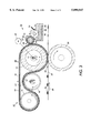
- FIG. 3 is schematic representation of yet another embodiment of a heat and pressure belt fuser according to the invention.
- one embodiment of the present invention comprises a heat and pressure belt fuser indicated generally by the reference character 10.
- a stretchable or elastic belt 12 is supported for movement in an endless path by a pair of rolls 14 and 16.
- the roll 14 is one of a pair of pressure engageable rolls while the roll 16 is an idler roll cooperating with the roll 14 to support the belt 12 for movement in and endless loop or path of movement in the direction of the arrow 18.
- a second pressure engageable roll 20 is supported for pressure engagement with the roll 14 such that the belt 12 is sandwiched therebetween in order to form a fusing nip 50.
- Imaged substrates such as a sheet of plain paper 24 carrying toner images 26 move in the direction of the arrow 28 pass through the nip 50 with the toner images contacting an outer surface 30 of the belt 12.
- the fusing nip 50 comprises a single nip, in that, the section of belt contacted by the roll 14 is coextensive with the opposite side of the belt contacted by roll 20. In other words, neither of the rolls 14 and 20 contact a section of the belt not contacted by the other of these two rolls.
- a single nip insures a single nip velocity through the entire nip.
- the deformable belt 12 preferably comprises silicone rubber of the type conventionally utilized in roll fusers.
- the thickness of the belt 12 is in the order of 0.006 to 0.125 inch.
- the deformable belt 12 provides the same function as the deformable layer of a Nip Forming Fuser Roll (NFFR), that is, it is self stripping.
- NFFR Nip Forming Fuser Roll
- smaller nip pressure rolls can be used in this belt fuser since the deformable belt, not the roll diameter, is the major contributor for generating the nip required for higher speed fixing of toner images. Smaller roll diameters also equate to more reliable stripping.
- Fusing surface 30 of the belt 12 is elevated to fusing temperature by means of an internally heated roll 40 having a conventional quartz heater 42 disposed internally thereof.
- the roll 40 comprises a relatively thin (0.050 to 0.2 inch) walled metal structure chosen for its good heat conducting properties. To this end the roll 40 may be fabricated from aluminum or steel.
- Another quartz heating structure 44 disposed internally of the roll 14 is provided for providing thermal energy only during fuser warm-up. By supplying the additional heat during warm-up the phenomena commonly referred to as droop is obviated.
- a motor 48 operatively connected to the roll 14 through a conventional drive mechanism (not shown) provides for rotation of the roll 14.
- the frictional interface between the belt 12 and the roll 14 and between the belt 12 and the rolls 16 and 40 causes those rolls to be driven by the belt.
- Separate drive mechanisms may be provided where necessary for imparting motion to the rolls 16, 20 and 40.
- a heat and pressure belt fuser may have a nip 50 created by a deformable layer 52 and a fusing belt 54.
- the layer 52 is carried by an internally heated roll structure.
- both the pressure engageable roll 56 and fusing belt 54 are employed factors such as cost, energy transfer and belt flexibility must be considered. If the belt is provided with all of the nip forming elastomeric material and that layer is relatively thick then the belt would be too costly as well as too inflexible for its intended purpose. If the roll is provided with too much of a thermal barrier then the high fusing speeds contemplated by the invention can't be realized.
- Each layer may have a thickness in the order of 0.006 to inch. However, the combined thickness must also be in that range of values.
- a fusing belt 60 may comprise a base layer 62 and an outer layer 64.
- the layer 64 comprises a 2 mil thick abhesive material such as VITONTM.
- the mechanism 70 comprises a donor roll 72, metering roll 74, doctor blade 76 and a wick 78.
- the metering roll 74 is partially immersed in the release agent material 80 and is supported for rotation such that it is contacted by the donor roll 72 which, in turn, is supported so as to be contacted by the fusing belt.
- the orientation of the rolls 72 and 74 is such as to provide a path for conveying material 80 from a sump 82 to the surface of the belt.
- the metering roll is preferably a nickel or chrome plated steel roll having a 4-32 M finish.
- the metering roll has an outside diameter of 1.0 to 1.5 inches.
- the metering roll is supported for rotation, such rotation being derived by means of friction between the belt and the rotatably supported donor roll 72.
- the donor roll 72 comprises a deformable layer 84 which forms a first nip 86 between the metering roll and the donor roll and a second nip 88 between the latter and the heated roll.
- the nips 84 and 88 also permit satisfactory release agent transfer between the rolls and the belt. Suitable nip lengths are about 0.10 inch.
- a similar RAM system is provided for the heated belt structures 54 and 60 shown in FIGS. 2 and 3, respectively.
- Wick 78 is fully immersed in the release agent and contacts the surface of the metering roll 74.
- the purpose of the wick is to provide an air seal which disturbs the air layer formed at the surface of the roll 74 during rotation thereof. If it were not for the function of the wick, the air layer would be coextensive with the surface of the roll immersed in the release agent thereby precluding contact between the metering roll and the release agent.
- the blade 76 preferably fabricated from Viton is 3/4 ⁇ 1/8 in cross section and has a length coextensive with the metering roll.
- the edge of the blade contacting the metering roll has a radius of 0.001-0.010 inch.
- the blade functions to meter the release agent picked up by the roll 74 to a predetermined thickness, such thickness being of such a magnitude as to result in several microliters of release agent consumption per copy.
- the donor roll 72 has an outside diameter of 1.0 inch when the metering roll's outside diameter equals 1.0 inch. It will be appreciated that other dimensional combinations will yield satisfactory results. For example, 1.5 inch diameter rolls for the donor and metering rolls have been employed.
- the deformable layer 84 of the donor roll preferably comprises overcoated silicone rubber. However, other materials may also be employed.
Landscapes
- Physics & Mathematics (AREA)
- General Physics & Mathematics (AREA)
- Fixing For Electrophotography (AREA)
Abstract
Description
Claims (11)
Priority Applications (4)
| Application Number | Priority Date | Filing Date | Title |
|---|---|---|---|
| US09/004,758 US5890047A (en) | 1998-01-08 | 1998-01-08 | Externally heated NFFR fuser |
| EP99300025A EP0929016B1 (en) | 1998-01-08 | 1999-01-04 | Fuser |
| DE69942882T DE69942882D1 (en) | 1998-01-08 | 1999-01-04 | Schmelzfixiergerät |
| JP11002621A JPH11249469A (en) | 1998-01-08 | 1999-01-08 | Heating and pressurizing belt fusion device and method for fixing toner image |
Applications Claiming Priority (1)
| Application Number | Priority Date | Filing Date | Title |
|---|---|---|---|
| US09/004,758 US5890047A (en) | 1998-01-08 | 1998-01-08 | Externally heated NFFR fuser |
Publications (1)
| Publication Number | Publication Date |
|---|---|
| US5890047A true US5890047A (en) | 1999-03-30 |
Family
ID=21712388
Family Applications (1)
| Application Number | Title | Priority Date | Filing Date |
|---|---|---|---|
| US09/004,758 Expired - Lifetime US5890047A (en) | 1998-01-08 | 1998-01-08 | Externally heated NFFR fuser |
Country Status (4)
| Country | Link |
|---|---|
| US (1) | US5890047A (en) |
| EP (1) | EP0929016B1 (en) |
| JP (1) | JPH11249469A (en) |
| DE (1) | DE69942882D1 (en) |
Cited By (23)
| Publication number | Priority date | Publication date | Assignee | Title |
|---|---|---|---|---|
| US5998761A (en) * | 1998-07-10 | 1999-12-07 | Xerox Corporation | Variable dwell fuser |
| US6091926A (en) * | 1998-03-27 | 2000-07-18 | Ricoh Company, Ltd. | Fixing device using a belt for an image forming apparatus |
| US6173152B1 (en) * | 1999-08-30 | 2001-01-09 | Xerox Corporation | Apertured fuser belt |
| US6226488B1 (en) * | 1997-05-07 | 2001-05-01 | Canon Kabushiki Kaisha | Fixing apparatus for controlling distance between heating means and guide member |
| US6246858B1 (en) * | 1999-08-02 | 2001-06-12 | Xerox Corporation | Electrostatographic reproduction machine having a fusing belt position changing mechanism |
| US6321061B1 (en) * | 1998-02-16 | 2001-11-20 | Kinyosha Co., Ltd. | Belt nip-type toner fixing apparatus using elastic endless belt |
| US6351619B1 (en) * | 1999-04-23 | 2002-02-26 | Ricoh Company, Ltd. | Image forming apparatus, belt type fixing device and heating control |
| US6377774B1 (en) | 2000-10-06 | 2002-04-23 | Lexmark International, Inc. | System for applying release fluid on a fuser roll of a printer |
| EP1205822A1 (en) * | 2000-10-13 | 2002-05-15 | Ricoh Company, Ltd. | Heat fixing device and image forming apparatus including the same |
| US6577840B2 (en) * | 1999-12-02 | 2003-06-10 | Ricoh Company, Ltd. | Method and apparatus for image forming capable of effectively performing an image fixing process |
| US6580895B2 (en) * | 2001-03-28 | 2003-06-17 | Hewlett-Packard Development Company, L.P. | Fusing system including a heat distribution mechanism |
| US6603936B2 (en) * | 2000-12-29 | 2003-08-05 | Kabushiki Kaisha Toshiba | Fixing apparatus and fixing method |
| US6643490B2 (en) * | 2001-12-12 | 2003-11-04 | Hewlett-Packard Development Company, Lp. | System for providing variable fusing energy to print media |
| US20040022552A1 (en) * | 2002-05-31 | 2004-02-05 | Jun Yura | Fixing device and image forming apparatus including the same |
| US20040052555A1 (en) * | 2002-09-16 | 2004-03-18 | Xerox Corporation | High speed heat and pressure belt fuser |
| US20040101333A1 (en) * | 2002-11-21 | 2004-05-27 | Nexpress Solutions Llc | Image production system with release agent system and associated method of controlling release agent transfer |
| US6757514B2 (en) | 2002-08-12 | 2004-06-29 | Xerox Corporation | High-speed heat and pressure belt fuser |
| US6782233B2 (en) * | 2002-03-08 | 2004-08-24 | Xerox Corporation | Externally heated thick belt fuser |
| US20050163542A1 (en) * | 2004-01-28 | 2005-07-28 | Gilmore James D. | Backup belt assembly for use in a fusing system and fusing systems therewith |
| US20060120776A1 (en) * | 2002-07-04 | 2006-06-08 | Fujita Takashi | Transfer fixing apparatus, fixing apparatus, toner image forming apparatus, method, and record medium recycled method |
| US20070071518A1 (en) * | 2005-09-23 | 2007-03-29 | Lexmark International, Inc. | Fusing system including a backup belt assembly |
| CN100340931C (en) * | 2003-02-27 | 2007-10-03 | 佳能株式会社 | Image heating plant |
| US20110188906A1 (en) * | 2010-01-29 | 2011-08-04 | Fuji Xerox Co., Ltd. | Fixing device and image forming apparatus |
Families Citing this family (2)
| Publication number | Priority date | Publication date | Assignee | Title |
|---|---|---|---|---|
| US8170436B2 (en) * | 2009-01-12 | 2012-05-01 | Xerox Corporation | Apparatuses useful for printing and methods of controlling a temperature of a surface in apparatuses useful for printing |
| US8143558B2 (en) * | 2009-01-13 | 2012-03-27 | Xerox Corporation | Apparatuses useful for printing and methods for controlling the temperature of media in apparatuses useful for printing |
Citations (6)
| Publication number | Priority date | Publication date | Assignee | Title |
|---|---|---|---|---|
| US4242566A (en) * | 1980-03-21 | 1980-12-30 | Pitney Bowes Inc. | Heat-pressure fusing device |
| US4582416A (en) * | 1984-10-31 | 1986-04-15 | Xerox Corporation | Low mass heat and pressure fuser |
| US4922304A (en) * | 1988-03-11 | 1990-05-01 | Imagitek | Reproduction machine fuser belt |
| US5250998A (en) * | 1991-02-28 | 1993-10-05 | Konica Corporation | Fixing apparatus having two nip regions |
| US5349424A (en) * | 1993-10-25 | 1994-09-20 | Xerox Corporation | Thick walled heated belt fuser |
| US5465146A (en) * | 1993-03-10 | 1995-11-07 | Nitto Kogyo Co., Ltd. | Fixing device for electrophotographic apparatus |
Family Cites Families (4)
| Publication number | Priority date | Publication date | Assignee | Title |
|---|---|---|---|---|
| US4197445A (en) * | 1978-09-27 | 1980-04-08 | Xerox Corporation | Roll fuser apparatus and system therefor |
| JPH0450883A (en) * | 1990-06-15 | 1992-02-19 | Ricoh Co Ltd | Fixing device for electrophotographic copying device |
| JPH09138600A (en) * | 1995-11-14 | 1997-05-27 | Minolta Co Ltd | Fixing device |
| US5697036A (en) * | 1996-08-12 | 1997-12-09 | Xerox Corporation | Single roll RAM system |
-
1998
- 1998-01-08 US US09/004,758 patent/US5890047A/en not_active Expired - Lifetime
-
1999
- 1999-01-04 EP EP99300025A patent/EP0929016B1/en not_active Expired - Lifetime
- 1999-01-04 DE DE69942882T patent/DE69942882D1/en not_active Expired - Lifetime
- 1999-01-08 JP JP11002621A patent/JPH11249469A/en active Pending
Patent Citations (6)
| Publication number | Priority date | Publication date | Assignee | Title |
|---|---|---|---|---|
| US4242566A (en) * | 1980-03-21 | 1980-12-30 | Pitney Bowes Inc. | Heat-pressure fusing device |
| US4582416A (en) * | 1984-10-31 | 1986-04-15 | Xerox Corporation | Low mass heat and pressure fuser |
| US4922304A (en) * | 1988-03-11 | 1990-05-01 | Imagitek | Reproduction machine fuser belt |
| US5250998A (en) * | 1991-02-28 | 1993-10-05 | Konica Corporation | Fixing apparatus having two nip regions |
| US5465146A (en) * | 1993-03-10 | 1995-11-07 | Nitto Kogyo Co., Ltd. | Fixing device for electrophotographic apparatus |
| US5349424A (en) * | 1993-10-25 | 1994-09-20 | Xerox Corporation | Thick walled heated belt fuser |
Cited By (33)
| Publication number | Priority date | Publication date | Assignee | Title |
|---|---|---|---|---|
| US6226488B1 (en) * | 1997-05-07 | 2001-05-01 | Canon Kabushiki Kaisha | Fixing apparatus for controlling distance between heating means and guide member |
| US6321061B1 (en) * | 1998-02-16 | 2001-11-20 | Kinyosha Co., Ltd. | Belt nip-type toner fixing apparatus using elastic endless belt |
| US6091926A (en) * | 1998-03-27 | 2000-07-18 | Ricoh Company, Ltd. | Fixing device using a belt for an image forming apparatus |
| US5998761A (en) * | 1998-07-10 | 1999-12-07 | Xerox Corporation | Variable dwell fuser |
| US6351619B1 (en) * | 1999-04-23 | 2002-02-26 | Ricoh Company, Ltd. | Image forming apparatus, belt type fixing device and heating control |
| US6246858B1 (en) * | 1999-08-02 | 2001-06-12 | Xerox Corporation | Electrostatographic reproduction machine having a fusing belt position changing mechanism |
| US6173152B1 (en) * | 1999-08-30 | 2001-01-09 | Xerox Corporation | Apertured fuser belt |
| US6577840B2 (en) * | 1999-12-02 | 2003-06-10 | Ricoh Company, Ltd. | Method and apparatus for image forming capable of effectively performing an image fixing process |
| US6377774B1 (en) | 2000-10-06 | 2002-04-23 | Lexmark International, Inc. | System for applying release fluid on a fuser roll of a printer |
| EP1205822A1 (en) * | 2000-10-13 | 2002-05-15 | Ricoh Company, Ltd. | Heat fixing device and image forming apparatus including the same |
| US6594464B2 (en) | 2000-10-13 | 2003-07-15 | Ricoh Company, Ltd. | Image forming apparatus including endless belt with reduced heat loss |
| US6603936B2 (en) * | 2000-12-29 | 2003-08-05 | Kabushiki Kaisha Toshiba | Fixing apparatus and fixing method |
| US6580895B2 (en) * | 2001-03-28 | 2003-06-17 | Hewlett-Packard Development Company, L.P. | Fusing system including a heat distribution mechanism |
| US6643490B2 (en) * | 2001-12-12 | 2003-11-04 | Hewlett-Packard Development Company, Lp. | System for providing variable fusing energy to print media |
| US6782233B2 (en) * | 2002-03-08 | 2004-08-24 | Xerox Corporation | Externally heated thick belt fuser |
| US20040022552A1 (en) * | 2002-05-31 | 2004-02-05 | Jun Yura | Fixing device and image forming apparatus including the same |
| US7010255B2 (en) * | 2002-05-31 | 2006-03-07 | Ricoh Company, Ltd. | Fixing device having a heating member and image forming apparatus including the same |
| US20060120776A1 (en) * | 2002-07-04 | 2006-06-08 | Fujita Takashi | Transfer fixing apparatus, fixing apparatus, toner image forming apparatus, method, and record medium recycled method |
| US7583922B2 (en) | 2002-07-04 | 2009-09-01 | Ricoh Company Limited | Image forming apparatus with a pressing member and transfer fixing member |
| US20080219716A1 (en) * | 2002-07-04 | 2008-09-11 | Fujita Takashi | Fixing apparatus with a pressing member and transfer fixing member |
| US7359666B2 (en) * | 2002-07-04 | 2008-04-15 | Ricoh Company Limited | Fixing apparatus with a pressing member and transfer fixing member |
| US6757514B2 (en) | 2002-08-12 | 2004-06-29 | Xerox Corporation | High-speed heat and pressure belt fuser |
| US20040052555A1 (en) * | 2002-09-16 | 2004-03-18 | Xerox Corporation | High speed heat and pressure belt fuser |
| US6795677B2 (en) | 2002-09-16 | 2004-09-21 | Xerox Corporation | High speed heat and pressure belt fuser |
| US7054588B2 (en) * | 2002-11-21 | 2006-05-30 | Eastman Kodak Company | Image production system with release agent system and associated method of controlling release agent transfer |
| US20040101333A1 (en) * | 2002-11-21 | 2004-05-27 | Nexpress Solutions Llc | Image production system with release agent system and associated method of controlling release agent transfer |
| CN100340931C (en) * | 2003-02-27 | 2007-10-03 | 佳能株式会社 | Image heating plant |
| US7020424B2 (en) | 2004-01-28 | 2006-03-28 | Lexmark International, Inc. | Backup belt assembly for use in a fusing system and fusing systems therewith |
| US20050163542A1 (en) * | 2004-01-28 | 2005-07-28 | Gilmore James D. | Backup belt assembly for use in a fusing system and fusing systems therewith |
| US20070071518A1 (en) * | 2005-09-23 | 2007-03-29 | Lexmark International, Inc. | Fusing system including a backup belt assembly |
| US7386264B2 (en) | 2005-09-23 | 2008-06-10 | Lexmark International, Inc. | Fusing system including a backup belt assembly |
| US20110188906A1 (en) * | 2010-01-29 | 2011-08-04 | Fuji Xerox Co., Ltd. | Fixing device and image forming apparatus |
| US8644744B2 (en) | 2010-01-29 | 2014-02-04 | Fuji Xerox Co., Ltd. | Fixing device and image forming apparatus |
Also Published As
| Publication number | Publication date |
|---|---|
| EP0929016A2 (en) | 1999-07-14 |
| EP0929016B1 (en) | 2010-10-27 |
| JPH11249469A (en) | 1999-09-17 |
| DE69942882D1 (en) | 2010-12-09 |
| EP0929016A3 (en) | 2001-01-17 |
Similar Documents
| Publication | Publication Date | Title |
|---|---|---|
| US5890047A (en) | Externally heated NFFR fuser | |
| CA1067132A (en) | Fuser roll having a non-uniform cross section | |
| US7493074B2 (en) | Fixing device, sheet member, and image forming apparatus | |
| US5051784A (en) | Image fixing apparatus with roughened film in sliding contact with heater | |
| US6795677B2 (en) | High speed heat and pressure belt fuser | |
| US5053829A (en) | Heat and pressure fuser with non-symmetrical nip pressure | |
| US6246858B1 (en) | Electrostatographic reproduction machine having a fusing belt position changing mechanism | |
| US5729812A (en) | Heat and pressure fuser utilizing rigid rolls and belts to form an extended contact zone between the belts including preheat and pressure zones | |
| US5227853A (en) | Compliant fusing roller | |
| JP2004226815A (en) | Heating device and image forming apparatus | |
| US6782233B2 (en) | Externally heated thick belt fuser | |
| JP3483423B2 (en) | Heating equipment | |
| US6198902B1 (en) | Electrostatographic reproduction machine including a dual function fusing belt deskewing and heating assembly | |
| US5420678A (en) | Pinch roll for a release material delivery system | |
| US6757514B2 (en) | High-speed heat and pressure belt fuser | |
| US6212352B1 (en) | Color image forming apparatus spacially separating toner image heat-fusion from toner image transfer to a recording medium | |
| JP2833088B2 (en) | Fixing device | |
| US6263181B1 (en) | Electrostatographic reproduction machine including a dual function fusing belt deskewing and oiling assembly | |
| JPH08234602A (en) | Fixing device and image forming device | |
| US5872350A (en) | Paper fire Preventer | |
| JPH0876625A (en) | Fixing roller of silicone and viton | |
| US4004549A (en) | Roll fuser | |
| CA1053316A (en) | Wetted heated internally conformable surface fuser | |
| JP2694734B2 (en) | Fixing device | |
| JP2000181267A (en) | Fixing device |
Legal Events
| Date | Code | Title | Description |
|---|---|---|---|
| AS | Assignment |
Owner name: XEROX CORPORATION, CONNECTICUT Free format text: ASSIGNMENT OF ASSIGNORS INTEREST;ASSIGNOR:MOSER, RABIN;REEL/FRAME:008926/0250 Effective date: 19971205 |
|
| STCF | Information on status: patent grant |
Free format text: PATENTED CASE |
|
| AS | Assignment |
Owner name: BANK ONE, NA, AS ADMINISTRATIVE AGENT, ILLINOIS Free format text: SECURITY INTEREST;ASSIGNOR:XEROX CORPORATION;REEL/FRAME:013153/0001 Effective date: 20020621 |
|
| FPAY | Fee payment |
Year of fee payment: 4 |
|
| AS | Assignment |
Owner name: JPMORGAN CHASE BANK, AS COLLATERAL AGENT, TEXAS Free format text: SECURITY AGREEMENT;ASSIGNOR:XEROX CORPORATION;REEL/FRAME:015134/0476 Effective date: 20030625 Owner name: JPMORGAN CHASE BANK, AS COLLATERAL AGENT,TEXAS Free format text: SECURITY AGREEMENT;ASSIGNOR:XEROX CORPORATION;REEL/FRAME:015134/0476 Effective date: 20030625 |
|
| FPAY | Fee payment |
Year of fee payment: 8 |
|
| FPAY | Fee payment |
Year of fee payment: 12 |
|
| AS | Assignment |
Owner name: XEROX CORPORATION, CONNECTICUT Free format text: RELEASE BY SECURED PARTY;ASSIGNOR:JPMORGAN CHASE BANK, N.A. AS SUCCESSOR-IN-INTEREST ADMINISTRATIVE AGENT AND COLLATERAL AGENT TO JPMORGAN CHASE BANK;REEL/FRAME:066728/0193 Effective date: 20220822 |