US5883498A - Battery-powered electrical device - Google Patents
Battery-powered electrical device Download PDFInfo
- Publication number
- US5883498A US5883498A US08/926,274 US92627497A US5883498A US 5883498 A US5883498 A US 5883498A US 92627497 A US92627497 A US 92627497A US 5883498 A US5883498 A US 5883498A
- Authority
- US
- United States
- Prior art keywords
- voltage
- cell
- battery pack
- bat
- subsets
- Prior art date
- Legal status (The legal status is an assumption and is not a legal conclusion. Google has not performed a legal analysis and makes no representation as to the accuracy of the status listed.)
- Expired - Fee Related
Links
Images
Classifications
-
- H—ELECTRICITY
- H02—GENERATION; CONVERSION OR DISTRIBUTION OF ELECTRIC POWER
- H02J—CIRCUIT ARRANGEMENTS OR SYSTEMS FOR SUPPLYING OR DISTRIBUTING ELECTRIC POWER; SYSTEMS FOR STORING ELECTRIC ENERGY
- H02J7/00—Circuit arrangements for charging or depolarising batteries or for supplying loads from batteries
- H02J7/0013—Circuit arrangements for charging or depolarising batteries or for supplying loads from batteries acting upon several batteries simultaneously or sequentially
-
- H—ELECTRICITY
- H02—GENERATION; CONVERSION OR DISTRIBUTION OF ELECTRIC POWER
- H02J—CIRCUIT ARRANGEMENTS OR SYSTEMS FOR SUPPLYING OR DISTRIBUTING ELECTRIC POWER; SYSTEMS FOR STORING ELECTRIC ENERGY
- H02J7/00—Circuit arrangements for charging or depolarising batteries or for supplying loads from batteries
- H02J7/0029—Circuit arrangements for charging or depolarising batteries or for supplying loads from batteries with safety or protection devices or circuits
- H02J7/00306—Overdischarge protection
Definitions
- the invention relates to a battery-powered electrical device comprising a rechargeable battery pack and a switchable voltage drain, the battery pack containing a set S of individual cells in series connection, the set S having a cardinal number N greater than two, each cell being characterized by:
- V end at which it is desirable to terminate discharge of the cell.
- cardinal number refers to the number of elements in a set, i.e. in this case the number of cells in the set S.
- nominal voltage refers to the (rated) voltage across the terminals of the cell when it is loaded ("battery pole voltage"), and specifically refers to the average voltage on the plateau of the cell's discharge curve.
- V min for a given application is a selected voltage-level through which even the weakest cell in the battery pack should not be allowed to discharge, under any circumstances.
- the value of V end for a given application is a selected voltage-level below which further discharge of the cell is of little use, since the remaining cell voltage will be insufficient to satisfactorily operate the device.
- Devices of this type are well known from everyday experience, and include, for example, electric power tools, video cameras, mini vacuum cleaners, lap-top computers, electronic notebooks, portable music sources, torches, mobile communication devices, etc. Because such devices are commonly designed to operate at a rated voltage which is higher than the nominal voltage V bat of common cells (e.g. 1.25 V), the devices must accordingly derive their power from series-arrays of such cells (i.e. battery packs).
- V bat of common cells e.g. 1.25 V
- V pack N ⁇ V end
- the set S is divided into a number of mutually exclusive subsets s i of cardinal number n i , whereby 0 ⁇ n i ⁇ N, at least one cardinal number n i is greater than 1, and the sum of all the cardinal numbers n i is equal to N;
- the device comprises means for measuring the series voltage V i across each subset s i , and interrupting the switchable voltage drain if the condition:
- Cut-off monitoring in the device according to the invention is neither based on measuring the voltage across the battery pack as a whole (n i ⁇ N) nor on individually measuring the voltage across each cell (n i >1 for at least one subset s i ). Instead, the battery pack is divided into subsets (subgroups) of cells, and the voltage across each of these subsets is monitored.
- the monitoring principle can be elucidated as follows:
- V i max (n i -1) ⁇ V bat +(1) ⁇ V min
- V bat For nickel metal hydride (NiMH) cells and NiCd cells, the value of V bat is generally about 1.25 V. This voltage remains substantially constant over a relatively wide portion of such a cell's discharge curve, then descends to a value of about 1.1 V before undergoing a sharp drop towards zero. A value of V end of the order of 0.85-1.0 V corresponds to the start of this sharp drop, just over the characteristic "knee" in the cell's discharge curve. In general, a value of zero can be used for V min , though higher values van be used if required or desired in a particular application.
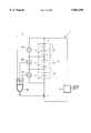
- FIGURE depicts a circuit diagram of a device according to the invention.
- the FIGURE depicts a particular embodiment of a device 1 according to the invention, such as an electric drill.
- the device 1 further comprises a voltage drain 5 (e.g. an electric motor), which is connected across the pack 3 via a switch 7.
- Each cell 31 is a NiMH battery, with a nominal voltage V bat ⁇ 1.25 V;
- V end is chosen to be 0.9 V.
- the battery pack 3 is divided into a number of mutually exclusive subsets s i , each of which has a cardinal number n i ⁇ 3.
- s i mutually exclusive subsets
- the device 1 further comprises means 9 for measuring the series voltage V i across each subset s i and comparing it with a reference voltage n i ⁇ V end .
- the means 9 comprise voltmeters 91, 92, 93 which respectively measure the voltages V 1 , V 2 , V 3 across each of the subsets s 1 , s 2 , s 3 , and compare them with the respective reference voltages 2.7 V, 2.7 V, 1.8 V.
- circuitry 7,9 can be incorporated into the battery pack 3, or it can be accommodated within part of the housing of the device 1.
- the battery pack 3 may be removable, so as to be rechargeable outside the device 1, or it may be permanently incorporated in the device 1, so as to be rechargeable in situ.
- Such an embodiment still satisfies the requirements:
Abstract
A battery-powered electrical device with a rechargeable battery pack and a means for preventing excessive discharge of the cells in the battery pack. Each cell is characterized by a voltage-value Vend at which it is desirable to terminate discharge of the cell. The cells are divided into a number of mutually exclusive subsets si having Ni cells. The device comprises means for measuring the series voltage Vi across each subset si, and interrupting the current to the device if the condition Vi ≦ni ×Vend is met in any of the subsets si.
Description
The invention relates to a battery-powered electrical device comprising a rechargeable battery pack and a switchable voltage drain, the battery pack containing a set S of individual cells in series connection, the set S having a cardinal number N greater than two, each cell being characterized by:
a nominal voltage Vbat ;
a minimal permissible voltage-value Vmin ;
a voltage-value Vend at which it is desirable to terminate discharge of the cell.
The term "cardinal number" refers to the number of elements in a set, i.e. in this case the number of cells in the set S. The term "nominal voltage" refers to the (rated) voltage across the terminals of the cell when it is loaded ("battery pole voltage"), and specifically refers to the average voltage on the plateau of the cell's discharge curve. The value of Vmin for a given application is a selected voltage-level through which even the weakest cell in the battery pack should not be allowed to discharge, under any circumstances. The value of Vend for a given application is a selected voltage-level below which further discharge of the cell is of little use, since the remaining cell voltage will be insufficient to satisfactorily operate the device.
2. Description of Related Art
Devices of this type are well known from everyday experience, and include, for example, electric power tools, video cameras, mini vacuum cleaners, lap-top computers, electronic notebooks, portable music sources, torches, mobile communication devices, etc. Because such devices are commonly designed to operate at a rated voltage which is higher than the nominal voltage Vbat of common cells (e.g. 1.25 V), the devices must accordingly derive their power from series-arrays of such cells (i.e. battery packs).
Many commonly-available battery-powered devices contain a voltage drain (e.g. a motor, lamp, electrical circuit, etc.) which simply continues to draw power from the battery pack until the pack's residual voltage is no longer sufficient to operate the device; the operator is then expected to recharge the battery pack before further use. However, it is now generally known that such depletory usage can be detrimental to the performance of the battery pack in the long run, since discharge of cells beyond a certain point can cause the occurrence of irreversible chemical reactions within the cells, which can damage their performance. For this reason, it is generally desirable to interrupt power to the voltage drain well before the battery pack becomes depleted, and then to recharge the battery pack before further use.
One way of performing this interruption is to choose a voltage-value Vend at which it is desirable to terminate discharge of the cell, to continually measure the voltage Vpack across the pack, and to interrupt power to the voltage drain as soon as Vpack =N×Vend (cut-off monitoring). A problem with such an approach, however, is that, if the pack contains a weak cell, then such a cell can still be over-discharged, despite the above-mentioned cut-off procedure. For example, if N=5, Vbat =1.25 V, Vmin =0 V and Vend =0.9 V, then N×Vend =4.5 V. However, if one of the cells is empty and the other four are full, then, initially, Vpack =4×1.25 V+0 V=5 V, which is greater than N×Vend (=4.5 V), so that cut-off will not yet occur. Under these circumstances, discharge of the battery pack will continue, despite the fact that one of the cells in the pack is already completely discharged. This will generally result in irreversible damage to the weak cell, causing it to weaken even further.
An alternative is to individually monitor each cell, and to interrupt the voltage drain as soon as the voltage across any given cell reaches Vend. However, this approach requires considerable extra circuitry, especially in the case of battery packs with relatively large values of N (more than 5, for example).
It is an object of the invention to provide a device as stated in the opening paragraph, in which device over-discharge of individual cells is prevented, without having to monitor each cell individually.
This object is achieved according to the invention in a device as specified in the opening paragraph, characterized in that:
the set S is divided into a number of mutually exclusive subsets si of cardinal number ni, whereby 0<ni <N, at least one cardinal number ni is greater than 1, and the sum of all the cardinal numbers ni is equal to N;
ni ≦n, where n is the largest natural number satisfying the relationship:
n<(Vbat -Vmin)/(Vbat -Vend);
the device comprises means for measuring the series voltage Vi across each subset si, and interrupting the switchable voltage drain if the condition:
Vi ≦ni ×Vend
is met in any of the subsets si.
The stipulation that the subsets si be mutually exclusive amounts to saying that no two subsets have a cell in common, i.e. si ∩sj =.O slashed., for any i≠j. In addition, none of the subsets is empty. It should be explicitly noted that the battery pack does not have to be physically divided up (i.e. split) into separate subsets si : rather, the subsets si should be viewed as administrative groupings within the battery pack, which remains intact.
Cut-off monitoring in the device according to the invention is neither based on measuring the voltage across the battery pack as a whole (ni <N) nor on individually measuring the voltage across each cell (ni >1 for at least one subset si). Instead, the battery pack is divided into subsets (subgroups) of cells, and the voltage across each of these subsets is monitored. The monitoring principle can be elucidated as follows:
(1) The stipulation:
ni <(Vbat -Vmin)/(Vbat -Vend)
can alternatively be written in the form:
(ni -1)×Vbat +Vmin <ni ×Vend.
(2) If, in a given subset si, the weakest cell has discharged as far as the minimum permissible voltage Vmin, then the maximum possible voltage across the subset si can never be more than:
Vi max =(ni -1)×Vbat +(1)×Vmin
=(ni -1)×Vbat +Vmin.
(3) Combining this with the previous inequality, it transpires that:
Vi max <ni ×Vend.
However, this falls within the cut-off condition:
Vi <ni ×Vend
It thus transpires that discharging cannot continue beyond the point where one of the cells has discharged as far as the minimum permissible voltage.
For nickel metal hydride (NiMH) cells and NiCd cells, the value of Vbat is generally about 1.25 V. This voltage remains substantially constant over a relatively wide portion of such a cell's discharge curve, then descends to a value of about 1.1 V before undergoing a sharp drop towards zero. A value of Vend of the order of 0.85-1.0 V corresponds to the start of this sharp drop, just over the characteristic "knee" in the cell's discharge curve. In general, a value of zero can be used for Vmin, though higher values van be used if required or desired in a particular application.
The invention and its attendant advantages will be further elucidated with the aid of exemplary embodiments and the accompanying schematic drawing, whereby the FIGURE depicts a circuit diagram of a device according to the invention.
The FIGURE depicts a particular embodiment of a device 1 according to the invention, such as an electric drill. The device 1 comprises a rechargeable battery pack 3 containing a set S of individual cells 31 in series connection; in this case, the set S has a cardinal number N=eight, i.e. the pack 3 contains eight cells 31. The device 1 further comprises a voltage drain 5 (e.g. an electric motor), which is connected across the pack 3 via a switch 7.
In this particular embodiment, the following considerations apply:
Each cell 31 is a NiMH battery, with a nominal voltage Vbat ≈1.25 V;
The voltage across any given cell 31 would, in principle, be allowed to drop as far as zero, but no further: consequently, Vmin =0 V;
Vend is chosen to be 0.9 V.
As a result, (Vbat -Vmin)/(Vbat -Vend)=1.25/0.35≈3.57, so that n=3 .
In accordance with this calculation, and in further accordance with the invention, the battery pack 3 is divided into a number of mutually exclusive subsets si, each of which has a cardinal number ni <3. In this particular case, there are three subsets S1, S2, s3 with respective cardinal numbers n1 =3, n2 =3, n3 =2, whereby Σni =3+3+2=8=N.
The device 1 further comprises means 9 for measuring the series voltage Vi across each subset si and comparing it with a reference voltage ni ×Vend. As here depicted, the means 9 comprise voltmeters 91, 92, 93 which respectively measure the voltages V1, V2, V3 across each of the subsets s1, s2, s3, and compare them with the respective reference voltages 2.7 V, 2.7 V, 1.8 V. If any of the values V1, V2, V3 is found to exceed the corresponding reference voltage, a signal is sent to the OR-gate 94 via one of its respective inputs I1, I2, I3 ; the output signal from the OR-gate 94 can then be used to open the switch 7, thereby interrupting the voltage drain 5.
It should be noted that the circuitry 7,9 can be incorporated into the battery pack 3, or it can be accommodated within part of the housing of the device 1. The battery pack 3 may be removable, so as to be rechargeable outside the device 1, or it may be permanently incorporated in the device 1, so as to be rechargeable in situ.
In an alternative scenario to that in Embodiment 1, the battery pack contains four subsets si, each with a cardinal number ni =2. Such an embodiment still satisfies the requirements:
ni ≦n=3;
Σni =N=8.
In yet another alternative, it is, for example, possible to select four subsets with cardinal numbers n1 =3, n2 =2, n3 =2, n4 =1.
Claims (1)
1. A battery-powered electrical device comprising a rechargeable battery pack and a switchable voltage drain, the battery pack comprising a set S of individual cells in series connection, the set S having a cardinal number N greater than two, each cell being characterized by:
a nominal voltage Vbat ;
a minimal permissible voltage-value Vmin ;
a voltage-value Vend at which it is desirable to terminate discharge of the cell, characterized in that:
the set S is divided into a number of mutually exclusive subsets si of cardinal number ni, whereby 0<ni <N, at least one cardinal number ni is greater than 1, and the sum of all the cardinal numbers ni is equal to N;
ni ≦n, where n is the largest natural number satisfying the relationship;
n<(Vbat -Vmin)/(Vbat -Vend);
the device comprises means for measuring the series voltage Vi ; across each subset si, and interrupting the switchable voltage drain if the condition;
Vi ≦ni ×Vend
is met in any of the subsets si.
Applications Claiming Priority (2)
| Application Number | Priority Date | Filing Date | Title |
|---|---|---|---|
| EP96202522 | 1996-09-10 | ||
| EP96202522 | 1996-09-10 |
Publications (1)
| Publication Number | Publication Date |
|---|---|
| US5883498A true US5883498A (en) | 1999-03-16 |
Family
ID=8224368
Family Applications (1)
| Application Number | Title | Priority Date | Filing Date |
|---|---|---|---|
| US08/926,274 Expired - Fee Related US5883498A (en) | 1996-09-10 | 1997-09-05 | Battery-powered electrical device |
Country Status (5)
| Country | Link |
|---|---|
| US (1) | US5883498A (en) |
| EP (1) | EP0864195B1 (en) |
| JP (1) | JP2000500320A (en) |
| DE (1) | DE69710702T2 (en) |
| WO (1) | WO1998011646A1 (en) |
Cited By (14)
| Publication number | Priority date | Publication date | Assignee | Title |
|---|---|---|---|---|
| US20060132093A1 (en) * | 2004-12-22 | 2006-06-22 | Nguyen Don J | Battery pack leakage cut-off |
| US20070298314A1 (en) * | 2006-06-23 | 2007-12-27 | Partin Phillip E | Lithium battery with external positive thermal coefficient layer |
| US20090269654A1 (en) * | 2008-04-24 | 2009-10-29 | Boston-Power, Inc. | Prismatic Storage Battery Or Cell With Flexible Recessed Portion |
| US20100108291A1 (en) * | 2008-09-12 | 2010-05-06 | Boston-Power, Inc. | Method and apparatus for embedded battery cells and thermal management |
| US20100164436A1 (en) * | 2005-07-14 | 2010-07-01 | Boston-Power, Inc. | Control Electronics for Li-ion Batteries |
| US20100289457A1 (en) * | 2009-05-18 | 2010-11-18 | Boston-Power, Inc. | Energy efficient and fast charge modes of a rechargeable battery |
| US20110052966A1 (en) * | 2004-12-28 | 2011-03-03 | Boston-Power, Inc. | Lithium-ion secondary battery |
| US20110049977A1 (en) * | 2009-09-01 | 2011-03-03 | Boston-Power, Inc. | Safety and performance optimized controls for large scale electric vehicle battery systems |
| US20110059349A1 (en) * | 2004-12-28 | 2011-03-10 | Boston-Power, Inc. | Lithium-ion secondary battery |
| US20110115434A1 (en) * | 2006-06-28 | 2011-05-19 | Boston-Power, Inc. | Electronics with multiple charge rate |
| US20110213509A1 (en) * | 2009-09-01 | 2011-09-01 | Boston-Power, Inc. | Large scale battery systems and method of assembly |
| US20120306503A1 (en) * | 2010-02-11 | 2012-12-06 | A123 Systems, Inc. | System and Method for Assessing Voltage Threshold Detecting Circuitry Within a Battery Pack |
| US8679670B2 (en) | 2007-06-22 | 2014-03-25 | Boston-Power, Inc. | CID retention device for Li-ion cell |
| CN104868449A (en) * | 2014-06-30 | 2015-08-26 | 北汽福田汽车股份有限公司 | Cell over-discharging protection method and system |
Families Citing this family (2)
| Publication number | Priority date | Publication date | Assignee | Title |
|---|---|---|---|---|
| US6939352B2 (en) | 2001-10-12 | 2005-09-06 | Cordis Corporation | Handle deployment mechanism for medical device and method |
| JP2005224024A (en) * | 2004-02-05 | 2005-08-18 | Makita Corp | Combined battery set and battery pack |
Citations (2)
| Publication number | Priority date | Publication date | Assignee | Title |
|---|---|---|---|---|
| US4622508A (en) * | 1984-08-20 | 1986-11-11 | Her Majesty The Queen In Right Of Canada, As Represented By The Minister Of National Defence Of Her Majesty's Canadian Government | Lithium battery protection circuit |
| US5206578A (en) * | 1991-10-15 | 1993-04-27 | Norvik Technologies Inc. | Monitoring system for batteries during charge and discharge |
-
1997
- 1997-07-15 WO PCT/IB1997/000875 patent/WO1998011646A1/en active IP Right Grant
- 1997-07-15 EP EP97929445A patent/EP0864195B1/en not_active Expired - Lifetime
- 1997-07-15 JP JP10513422A patent/JP2000500320A/en not_active Ceased
- 1997-07-15 DE DE69710702T patent/DE69710702T2/en not_active Expired - Fee Related
- 1997-09-05 US US08/926,274 patent/US5883498A/en not_active Expired - Fee Related
Patent Citations (2)
| Publication number | Priority date | Publication date | Assignee | Title |
|---|---|---|---|---|
| US4622508A (en) * | 1984-08-20 | 1986-11-11 | Her Majesty The Queen In Right Of Canada, As Represented By The Minister Of National Defence Of Her Majesty's Canadian Government | Lithium battery protection circuit |
| US5206578A (en) * | 1991-10-15 | 1993-04-27 | Norvik Technologies Inc. | Monitoring system for batteries during charge and discharge |
Cited By (25)
| Publication number | Priority date | Publication date | Assignee | Title |
|---|---|---|---|---|
| WO2006069365A2 (en) * | 2004-12-22 | 2006-06-29 | Intel Corporation | Battery pack leakage cut-off |
| WO2006069365A3 (en) * | 2004-12-22 | 2006-08-10 | Intel Corp | Battery pack leakage cut-off |
| US20060132093A1 (en) * | 2004-12-22 | 2006-06-22 | Nguyen Don J | Battery pack leakage cut-off |
| US20110052966A1 (en) * | 2004-12-28 | 2011-03-03 | Boston-Power, Inc. | Lithium-ion secondary battery |
| US8828605B2 (en) | 2004-12-28 | 2014-09-09 | Boston-Power, Inc. | Lithium-ion secondary battery |
| US20110059349A1 (en) * | 2004-12-28 | 2011-03-10 | Boston-Power, Inc. | Lithium-ion secondary battery |
| US8084998B2 (en) * | 2005-07-14 | 2011-12-27 | Boston-Power, Inc. | Method and device for controlling a storage voltage of a battery pack |
| US20100164436A1 (en) * | 2005-07-14 | 2010-07-01 | Boston-Power, Inc. | Control Electronics for Li-ion Batteries |
| US8003241B2 (en) | 2006-06-23 | 2011-08-23 | Boston-Power, Inc. | Lithium battery with external positive thermal coefficient layer |
| US20070298314A1 (en) * | 2006-06-23 | 2007-12-27 | Partin Phillip E | Lithium battery with external positive thermal coefficient layer |
| US20110115434A1 (en) * | 2006-06-28 | 2011-05-19 | Boston-Power, Inc. | Electronics with multiple charge rate |
| US8138726B2 (en) | 2006-06-28 | 2012-03-20 | Boston-Power, Inc. | Electronics with multiple charge rate |
| US8679670B2 (en) | 2007-06-22 | 2014-03-25 | Boston-Power, Inc. | CID retention device for Li-ion cell |
| US9166206B2 (en) | 2008-04-24 | 2015-10-20 | Boston-Power, Inc. | Prismatic storage battery or cell with flexible recessed portion |
| US20090269654A1 (en) * | 2008-04-24 | 2009-10-29 | Boston-Power, Inc. | Prismatic Storage Battery Or Cell With Flexible Recessed Portion |
| US20100108291A1 (en) * | 2008-09-12 | 2010-05-06 | Boston-Power, Inc. | Method and apparatus for embedded battery cells and thermal management |
| US20100289457A1 (en) * | 2009-05-18 | 2010-11-18 | Boston-Power, Inc. | Energy efficient and fast charge modes of a rechargeable battery |
| US8483886B2 (en) | 2009-09-01 | 2013-07-09 | Boston-Power, Inc. | Large scale battery systems and method of assembly |
| US20110049977A1 (en) * | 2009-09-01 | 2011-03-03 | Boston-Power, Inc. | Safety and performance optimized controls for large scale electric vehicle battery systems |
| US20110213509A1 (en) * | 2009-09-01 | 2011-09-01 | Boston-Power, Inc. | Large scale battery systems and method of assembly |
| US20120306503A1 (en) * | 2010-02-11 | 2012-12-06 | A123 Systems, Inc. | System and Method for Assessing Voltage Threshold Detecting Circuitry Within a Battery Pack |
| US9157967B2 (en) * | 2010-02-11 | 2015-10-13 | A123 Systems Llc | System and method for assessing voltage threshold detecting circuitry within a battery pack |
| US10067197B2 (en) | 2010-02-11 | 2018-09-04 | A123 Systems Llc | System and method for assessing voltage threshold detecting circuitry within a battery pack |
| CN104868449A (en) * | 2014-06-30 | 2015-08-26 | 北汽福田汽车股份有限公司 | Cell over-discharging protection method and system |
| CN104868449B (en) * | 2014-06-30 | 2017-11-03 | 北汽福田汽车股份有限公司 | A kind of battery cell Cross prevention method and system |
Also Published As
| Publication number | Publication date |
|---|---|
| DE69710702T2 (en) | 2004-05-06 |
| EP0864195B1 (en) | 2002-02-27 |
| WO1998011646A1 (en) | 1998-03-19 |
| EP0864195A1 (en) | 1998-09-16 |
| JP2000500320A (en) | 2000-01-11 |
| DE69710702D1 (en) | 2002-04-04 |
Similar Documents
| Publication | Publication Date | Title |
|---|---|---|
| US6885168B2 (en) | Battery unit having means for preventing over-discharge | |
| US5883498A (en) | Battery-powered electrical device | |
| JP3618472B2 (en) | Battery unit and device using battery unit | |
| US5929602A (en) | Controlled battery charger for charging multiple batteries | |
| CN100533912C (en) | Systems and methods for regulating pre-charge current in a battery system | |
| JP3869585B2 (en) | Discharge method of multiple secondary batteries and assembled battery | |
| JP5439000B2 (en) | Battery assembly system and battery protection device | |
| KR101201139B1 (en) | Protection circuit device of battery pack | |
| US5554919A (en) | Charge/discharge circuit having a simple circuit for protecting a secondary cell from overcharging and overdischarging | |
| JP2872365B2 (en) | Rechargeable power supply | |
| CN1199935A (en) | Series-connected circuit for secondary batteries | |
| US20060082345A1 (en) | Rechargeable alkaline battery with overcharging protection | |
| US8665572B2 (en) | Battery charge/discharge protection circuit | |
| US20050088147A1 (en) | Battery protection circuit | |
| JPH0956056A (en) | Secondary-battery power unit, protective circuit, and method for protecting secondary battery from being abnormally charged | |
| JPH1198702A (en) | Battery abnormality detector and battery pack | |
| JP3691347B2 (en) | Electrical equipment with built-in secondary battery | |
| US7056619B2 (en) | Chargeable battery for medical diagnostic instruments | |
| EP0854556A2 (en) | Charger and charging method for non-aqueous electrolyte secondary batteries | |
| JP3100248U (en) | Secondary battery storage and power supply device and secondary battery pack using the same | |
| KR102491116B1 (en) | Protection Circuit Module for Super capacitor | |
| EP3772153B1 (en) | Battery protection system | |
| KR200374547Y1 (en) | Portable charging apparatus | |
| Mubdir et al. | Smart charger for sealed lead acid batteries based on parallel port PC interfacing | |
| JPH05328622A (en) | Power device |
Legal Events
| Date | Code | Title | Description |
|---|---|---|---|
| AS | Assignment |
Owner name: U.S. PHILIPS CORPORATION, NEW YORK Free format text: ASSIGNMENT OF ASSIGNORS INTEREST;ASSIGNORS:VAN BEEK, JOHANN R.G.C.M.;GILLISSEN, EDUARD E.A.;REEL/FRAME:008938/0076;SIGNING DATES FROM 19971009 TO 19971014 |
|
| FPAY | Fee payment |
Year of fee payment: 4 |
|
| REMI | Maintenance fee reminder mailed | ||
| LAPS | Lapse for failure to pay maintenance fees | ||
| STCH | Information on status: patent discontinuation |
Free format text: PATENT EXPIRED DUE TO NONPAYMENT OF MAINTENANCE FEES UNDER 37 CFR 1.362 |
|
| FP | Lapsed due to failure to pay maintenance fee |
Effective date: 20070316 |