US5869914A - Piloted assembly - Google Patents
Piloted assembly Download PDFInfo
- Publication number
- US5869914A US5869914A US08/957,727 US95772797A US5869914A US 5869914 A US5869914 A US 5869914A US 95772797 A US95772797 A US 95772797A US 5869914 A US5869914 A US 5869914A
- Authority
- US
- United States
- Prior art keywords
- bore
- machined
- housing
- stator
- rotor
- Prior art date
- Legal status (The legal status is an assumption and is not a legal conclusion. Google has not performed a legal analysis and makes no representation as to the accuracy of the status listed.)
- Expired - Lifetime
Links
Images


Classifications
-
- H—ELECTRICITY
- H02—GENERATION; CONVERSION OR DISTRIBUTION OF ELECTRIC POWER
- H02K—DYNAMO-ELECTRIC MACHINES
- H02K15/00—Methods or apparatus specially adapted for manufacturing, assembling, maintaining or repairing of dynamo-electric machines
- H02K15/16—Centering rotors within the stator; Balancing rotors
-
- Y—GENERAL TAGGING OF NEW TECHNOLOGICAL DEVELOPMENTS; GENERAL TAGGING OF CROSS-SECTIONAL TECHNOLOGIES SPANNING OVER SEVERAL SECTIONS OF THE IPC; TECHNICAL SUBJECTS COVERED BY FORMER USPC CROSS-REFERENCE ART COLLECTIONS [XRACs] AND DIGESTS
- Y10—TECHNICAL SUBJECTS COVERED BY FORMER USPC
- Y10T—TECHNICAL SUBJECTS COVERED BY FORMER US CLASSIFICATION
- Y10T29/00—Metal working
- Y10T29/49—Method of mechanical manufacture
- Y10T29/49002—Electrical device making
- Y10T29/49009—Dynamoelectric machine
- Y10T29/49012—Rotor
Definitions
- the motor housing is provided with a machined diameter which serves as a basic reference location.
- the stator is provided with a machined diameter and is pressed into the machined diameter of the motor housing.
- a subassembly is made up of the shaft, the rotor and the cone assemblies of the two housings.
- the cups of the two bearings are respectively located in bores in the motor and rotor bearings. The subassembly is then inserted into the motor housing with the rotor being located within the bore in the stator while the cone of the motor housing bearing is positioned in the cup located in the bore in the motor housing.
- the resulting assembly which is made up of the subassembly and motor housing is assembled to the rotor housing by inserting the inner cone and rollers of the rotor housing bearing into the outer cup located in the bore in the motor housing as the overhung portion of the stator is inserted into the machined diameter of the rotor housing.
- a single machined diameter on the stator accomplishes the alignment of the bearings in the two housings through the coaction of the machined diameters on the motor housing and stator.
- This method of assembly eliminates two dowel pins and their associated precision machined holes.
- two housing members and the stator are precision machined on diameters and press fit such that the machined diameters coact to locate the members which then serve as a reference for subsequently assembled parts.
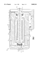
- FIG. 1 is a sectional view of a portion of a screw compressor assembled according to the teachings of the present invention
- FIG. 2 is an exploded view corresponding to FIG. 1;
- FIG. 3 is a flow diagram showing the assembly steps of the present invention.
- the numeral 10 generally designates a semi-hermetic screw compressor having a motor housing 12 and a rotor housing 14 which coact to define a motor chamber 16.
- a motor made up of stator 21 and rotor 22 is located in motor chamber 16.
- Rotor 22 is shrunk fit onto or otherwise suitably secured to shaft 30 which is rotatably supported by straddled bearings 32 and 34.
- Bearing 32 and stack of wavy springs 38 are received in bore 12-1 of motor housing 12 with springs 38 supported by shoulder 12-2 and tending to bias bearing 32 and thereby shaft 30 towards rotor housing 14.
- Bearing 34 is received in bore 14-1 of rotor housing 14 and is supported by shoulder 14-2. Shoulders 30-1 and 30-2 on shaft 30 engage bearings 32 and 34, respectively.
- Shaft 30 extends through bearing 34 and bore 14-3 into a gear housing (not illustrated) where it engages a drive gear (not illustrated).
- bearings 32 and 34 include inner cones and rollers 32-1 and 34-1, respectively, as well as outer cups 32-2 and 34-2, respectively. Accordingly, inner cones and rollers 32-1 and 34-1 can be separately assembled with respect to corresponding outer cups 32-2 and 34-2, respectively, and vice versa
- FIG. 3 The steps for the assembly of the motor and related structure for a screw compressor is shown in FIG. 3.
- box 100 the diameter of the bore 12-3 of motor housing 12 is precision machined so as to provide a reference for locating other members.
- Bore 12-1 is concentrically machined with respect to bore 12-3 so as to properly locate bearing 32.
- the diameter of outer cylindrical surface 21-2 of stator 21 is precision machined, as indicated by box 102, so as to be accurately received in bore 12-3.
- stator 21 is placed in motor housing 12 such that surface 21-2 is received in and engages bore 12-3.
- Spring 38 and outer cup 32-2 are placed in bore 12-1, as indicated by box 106.
- a subassembly is made from shaft 30, rotor 22, and inner bearings 32-1 and 34-1 as indicated by box 108.
- the subassembly of box 108 is placed such that rotor 22 is located in stator 21 and inner bearing 32-1 is received in outer cup 32-2, as indicated by box 110.
- Rotor housing bores 14-1 and 14-4 are machined concentrically, as indicated by box 112. Bore 14-4 must be of essentially the same diameter as bore 12-3 since they both receive and engage surface 21-2 of stator 21. In actual practice, bore 12-3 is in a tight interference fit with surface 21-2 whereas bore 14-4 is in a looser, slip fit with surface 21-2. Accordingly, bore 14-4 is slightly larger than bore 12-3 by an amount necessary to accommodate the looser fit.
- Outer cup 34-2 is placed in bore 14-1, as indicated by box 114.
- Motor housing 12 and rotor housing 14 are assembled together such that stator 21 is received in housing 14 with surface 21-2 engaging bore 144 and with inner bearing 34-1 received in outer cup 34-2, as indicated by box 116.
- the laminations could be precision stamped and assembled so as to provide an adequately dimensioned, but non-machined outer diameter since the ultimate criterion is the precision of the dimension of the outer diameter.
- the present invention has been described in terms of a two-piece roller bearing, the two main alternates are single-piece rolling bearings, such as ball bearings, and sleeve (or journal) type bearings. In the case of the single-piece ball bearings, the entire assembly can be installed either on the shaft or in the housing, even alternately from one end to the other.
- a single bearing insert can be installed either on the shaft, in the housing (most likely), or alternately from one end to the other.
- the insert may or may not be machined after installation. If it is not machined, the qualifying diameter is the bore into which (or the diameter over which) it is pressed. If it is machined, the qualifying diameter becomes the machined surface of the bearing itself. It is therefore intended that the scope of the present invention is to be limited only by the scope of the appended claims.
Abstract
Two housing members and the stator are precision machined on diameters and assembled such that the machined diameters coact to locate the members which then serve as a reference location for the subsequently assembled parts. The present invention reduces the number of critical machined features compared to a piloted assembly.
Description
This application is a division of application Ser. No. 08/753,629 filed Nov. 27, 1996, now U.S. Pat. No. 5,758,404.
In devices such as compressors it is common to have the motor, as well as the pump structure, in a semi-hermetic casing or housing with the motor supported by straddled bearings. The motor structure must be accurately located with respect to the pump structure for proper operation and to avoid undue stress and wear. Conventional assemblies of this type use, for example, locating features such as dowel pins to make the critical alignment of the housing components. This adds critical features to the machining and inspection process. It also increases capital costs for machining and inspection.
The motor housing is provided with a machined diameter which serves as a basic reference location. The stator is provided with a machined diameter and is pressed into the machined diameter of the motor housing. A subassembly is made up of the shaft, the rotor and the cone assemblies of the two housings. The cups of the two bearings are respectively located in bores in the motor and rotor bearings. The subassembly is then inserted into the motor housing with the rotor being located within the bore in the stator while the cone of the motor housing bearing is positioned in the cup located in the bore in the motor housing. The resulting assembly which is made up of the subassembly and motor housing is assembled to the rotor housing by inserting the inner cone and rollers of the rotor housing bearing into the outer cup located in the bore in the motor housing as the overhung portion of the stator is inserted into the machined diameter of the rotor housing. In this manner, a single machined diameter on the stator accomplishes the alignment of the bearings in the two housings through the coaction of the machined diameters on the motor housing and stator. This method of assembly eliminates two dowel pins and their associated precision machined holes.
It is an object of this invention to reduce the number of critical machined features in a piloted assembly.
It is a further object of this invention to achieve alignment using features on the motor itself to effect alignment of the housings. These objects, and others as will become apparent hereinafter, are accomplished by the present invention.
Basically, two housing members and the stator are precision machined on diameters and press fit such that the machined diameters coact to locate the members which then serve as a reference for subsequently assembled parts.
For a fuller understanding of the present invention, reference should now be made to the following detailed description thereof taken in conjunction with the accompanying drawings wherein:
FIG. 1 is a sectional view of a portion of a screw compressor assembled according to the teachings of the present invention;
FIG. 2 is an exploded view corresponding to FIG. 1; and
FIG. 3 is a flow diagram showing the assembly steps of the present invention.
In FIGS. 1 and 2, the numeral 10 generally designates a semi-hermetic screw compressor having a motor housing 12 and a rotor housing 14 which coact to define a motor chamber 16. A motor made up of stator 21 and rotor 22 is located in motor chamber 16. Rotor 22 is shrunk fit onto or otherwise suitably secured to shaft 30 which is rotatably supported by straddled bearings 32 and 34. Bearing 32 and stack of wavy springs 38 are received in bore 12-1 of motor housing 12 with springs 38 supported by shoulder 12-2 and tending to bias bearing 32 and thereby shaft 30 towards rotor housing 14. Bearing 34 is received in bore 14-1 of rotor housing 14 and is supported by shoulder 14-2. Shoulders 30-1 and 30-2 on shaft 30 engage bearings 32 and 34, respectively. Shaft 30 extends through bearing 34 and bore 14-3 into a gear housing (not illustrated) where it engages a drive gear (not illustrated).
Referring specifically to FIG. 2, it will be noted that bearings 32 and 34 include inner cones and rollers 32-1 and 34-1, respectively, as well as outer cups 32-2 and 34-2, respectively. Accordingly, inner cones and rollers 32-1 and 34-1 can be separately assembled with respect to corresponding outer cups 32-2 and 34-2, respectively, and vice versa
The steps for the assembly of the motor and related structure for a screw compressor is shown in FIG. 3. As indicated by box 100, the diameter of the bore 12-3 of motor housing 12 is precision machined so as to provide a reference for locating other members. Bore 12-1 is concentrically machined with respect to bore 12-3 so as to properly locate bearing 32. The diameter of outer cylindrical surface 21-2 of stator 21 is precision machined, as indicated by box 102, so as to be accurately received in bore 12-3. As indicated by box 104, stator 21 is placed in motor housing 12 such that surface 21-2 is received in and engages bore 12-3. Spring 38 and outer cup 32-2 are placed in bore 12-1, as indicated by box 106. A subassembly is made from shaft 30, rotor 22, and inner bearings 32-1 and 34-1 as indicated by box 108. The subassembly of box 108 is placed such that rotor 22 is located in stator 21 and inner bearing 32-1 is received in outer cup 32-2, as indicated by box 110. Rotor housing bores 14-1 and 14-4 are machined concentrically, as indicated by box 112. Bore 14-4 must be of essentially the same diameter as bore 12-3 since they both receive and engage surface 21-2 of stator 21. In actual practice, bore 12-3 is in a tight interference fit with surface 21-2 whereas bore 14-4 is in a looser, slip fit with surface 21-2. Accordingly, bore 14-4 is slightly larger than bore 12-3 by an amount necessary to accommodate the looser fit. Outer cup 34-2 is placed in bore 14-1, as indicated by box 114. Motor housing 12 and rotor housing 14 are assembled together such that stator 21 is received in housing 14 with surface 21-2 engaging bore 144 and with inner bearing 34-1 received in outer cup 34-2, as indicated by box 116.
From the foregoing description it should be clear that precision machined surface 21-2 of stator 21 coacts with precision machined bores 12-3 and 14-4 to precisely locate the motor housing 12 and the rotor housing 14 with respect to the stator 21 as well as to each other. Because bores 12-1 and 14-1 are machined concentrically with bores 12-3 and 14-4, respectively, the bearings 32 and 34 and therefore shaft 30 are accurately located.
Although a preferred embodiment of the present invention has been illustrated and described, other changes will occur to those skilled in the art. For example, rather than having a machined stator outer diameter, the laminations could be precision stamped and assembled so as to provide an adequately dimensioned, but non-machined outer diameter since the ultimate criterion is the precision of the dimension of the outer diameter. Although the present invention has been described in terms of a two-piece roller bearing, the two main alternates are single-piece rolling bearings, such as ball bearings, and sleeve (or journal) type bearings. In the case of the single-piece ball bearings, the entire assembly can be installed either on the shaft or in the housing, even alternately from one end to the other. In the case of sleeve bearings, again a single bearing insert can be installed either on the shaft, in the housing (most likely), or alternately from one end to the other. In this case, the insert may or may not be machined after installation. If it is not machined, the qualifying diameter is the bore into which (or the diameter over which) it is pressed. If it is machined, the qualifying diameter becomes the machined surface of the bearing itself. It is therefore intended that the scope of the present invention is to be limited only by the scope of the appended claims.
Claims (3)
1. A piloted assembly comprising:
a first housing member having first and second precision machined bores which are concentric;
a second housing member having first and second precision machined bores which are concentric;
a stator having a bore and a precision outer diameter;
said stator located in said first bore of said first housing member in a tight fit and in said first bore of second housing member with said housing members being secured together in a fluidtight relationship;
bearing means located in said second bores of said first and second housing members;
a shaft;
a rotor secured to said shaft;
said rotor being located in said bore of said stator with said shaft being supported by said bearing means.
2. The assembly of claim 1 wherein said first and second bores of said first and second housing members are axially spaced.
3. The piloted assembly of claim 1 wherein said tight fit is an interference fit.
Priority Applications (1)
| Application Number | Priority Date | Filing Date | Title |
|---|---|---|---|
| US08/957,727 US5869914A (en) | 1996-11-27 | 1997-10-24 | Piloted assembly |
Applications Claiming Priority (2)
| Application Number | Priority Date | Filing Date | Title |
|---|---|---|---|
| US08/753,629 US5758404A (en) | 1996-11-27 | 1996-11-27 | Method of assembling a motor |
| US08/957,727 US5869914A (en) | 1996-11-27 | 1997-10-24 | Piloted assembly |
Related Parent Applications (1)
| Application Number | Title | Priority Date | Filing Date |
|---|---|---|---|
| US08/753,629 Division US5758404A (en) | 1996-11-27 | 1996-11-27 | Method of assembling a motor |
Publications (1)
| Publication Number | Publication Date |
|---|---|
| US5869914A true US5869914A (en) | 1999-02-09 |
Family
ID=25031477
Family Applications (2)
| Application Number | Title | Priority Date | Filing Date |
|---|---|---|---|
| US08/753,629 Expired - Lifetime US5758404A (en) | 1996-11-27 | 1996-11-27 | Method of assembling a motor |
| US08/957,727 Expired - Lifetime US5869914A (en) | 1996-11-27 | 1997-10-24 | Piloted assembly |
Family Applications Before (1)
| Application Number | Title | Priority Date | Filing Date |
|---|---|---|---|
| US08/753,629 Expired - Lifetime US5758404A (en) | 1996-11-27 | 1996-11-27 | Method of assembling a motor |
Country Status (8)
| Country | Link |
|---|---|
| US (2) | US5758404A (en) |
| EP (1) | EP0851558B1 (en) |
| JP (1) | JPH10174349A (en) |
| KR (1) | KR100302089B1 (en) |
| CN (1) | CN1069456C (en) |
| BR (1) | BR9705910B1 (en) |
| DE (1) | DE69734434T2 (en) |
| ES (1) | ES2247620T3 (en) |
Cited By (4)
| Publication number | Priority date | Publication date | Assignee | Title |
|---|---|---|---|---|
| GB2358741A (en) * | 1999-12-20 | 2001-08-01 | Ford Global Tech Inc | Pilot-less self-centring installation of a starter-alternator |
| GB2358742A (en) * | 2000-01-05 | 2001-08-01 | Ford Global Tech Inc | Starter-alternator installation |
| US20040124727A1 (en) * | 2002-12-21 | 2004-07-01 | Lau Kevin King Wai | Motor and gearbox combination |
| US20060071564A1 (en) * | 2004-10-04 | 2006-04-06 | Stewart William P | Apparatus and methods of retaining a stator within a housing of an electric machine |
Families Citing this family (15)
| Publication number | Priority date | Publication date | Assignee | Title |
|---|---|---|---|---|
| JPH0946983A (en) * | 1995-05-23 | 1997-02-14 | Fanuc Ltd | Method for finishing frame of motor, and motor to be finished by the method |
| US5767596A (en) * | 1996-10-03 | 1998-06-16 | General Electric Company | Dynamoelectric machine and processes for making the same |
| US6122817A (en) * | 1997-09-19 | 2000-09-26 | Alliedsignal Inc. | Rotor assembly having lamination stack that is separately piloted and clamped |
| US6148501A (en) * | 1998-04-14 | 2000-11-21 | Seagate Technology Llc | Fabrication means for in-hub spindle with separate fluid dynamic bearings |
| US7091640B2 (en) * | 2004-05-26 | 2006-08-15 | Emerson Electric Co. | Motor with a multifunction bearing cap and method of assembly |
| US7931448B2 (en) * | 2006-08-01 | 2011-04-26 | Federal Mogul World Wide, Inc. | System and method for manufacturing a brushless DC motor fluid pump |
| US8488293B2 (en) * | 2009-12-21 | 2013-07-16 | Caterpillar Inc. | Electrical bearing ground device |
| CN102170198B (en) * | 2011-04-15 | 2014-10-22 | 无锡新大力电机有限公司 | Permanent magnet motor assembling tool |
| US9496775B2 (en) * | 2013-06-19 | 2016-11-15 | Tesla Motors, Inc. | Controlling end ring balance in pre-balancing spinning process |
| EP3284027B1 (en) | 2015-04-14 | 2021-09-22 | Capital One Services, LLC | Tamper-resistant dynamic transaction card and method of providing a tamper-resistant dynamic transaction card |
| CN108533492B (en) * | 2018-02-05 | 2020-02-07 | 珠海格力电器股份有限公司 | Compressor and air conditioner with same |
| US11791675B2 (en) * | 2020-03-06 | 2023-10-17 | Lc Advanced Motor Technology Corporation | Housing for a rotary electric machine and associated laminations |
| CN111953159B (en) * | 2020-08-14 | 2021-08-17 | 浙江震环数控机床股份有限公司 | Conical motor casing processing equipment and using method thereof |
| DE102020212589A1 (en) * | 2020-10-06 | 2022-04-07 | Zf Friedrichshafen Ag | Shaft grounding assembly, gearbox, and electric final drive |
| DE102021213387A1 (en) * | 2021-11-29 | 2023-06-01 | Zf Friedrichshafen Ag | Arrangement for grounding a shaft |
Citations (5)
| Publication number | Priority date | Publication date | Assignee | Title |
|---|---|---|---|---|
| US2819417A (en) * | 1954-11-18 | 1958-01-07 | John P Glass | Synchro construction and method for making same |
| US3268986A (en) * | 1963-05-07 | 1966-08-30 | Gen Electric | Method of manufacturing dynamo-electric machines |
| US3814961A (en) * | 1972-08-02 | 1974-06-04 | Ambac Ind | Trolling motor structure |
| US4118644A (en) * | 1974-10-12 | 1978-10-03 | Firma Schulte Elektrotechnik Kg | Electrical machinery |
| US4955128A (en) * | 1987-02-17 | 1990-09-11 | Fanuc Ltd. | Method for inserting rotor of electric motor |
Family Cites Families (3)
| Publication number | Priority date | Publication date | Assignee | Title |
|---|---|---|---|---|
| JPS558253A (en) * | 1978-06-30 | 1980-01-21 | Matsushita Electric Works Ltd | Motor |
| US4736869A (en) * | 1986-08-22 | 1988-04-12 | Expert Corporation | Submersible sealed housing |
| US5287030A (en) * | 1992-03-23 | 1994-02-15 | Electric Motors And Specialties, Inc. | Electric motor construction |
-
1996
- 1996-11-27 US US08/753,629 patent/US5758404A/en not_active Expired - Lifetime
-
1997
- 1997-10-24 US US08/957,727 patent/US5869914A/en not_active Expired - Lifetime
- 1997-11-14 EP EP97630078A patent/EP0851558B1/en not_active Expired - Lifetime
- 1997-11-14 DE DE69734434T patent/DE69734434T2/en not_active Expired - Lifetime
- 1997-11-14 ES ES97630078T patent/ES2247620T3/en not_active Expired - Lifetime
- 1997-11-24 CN CN97123002A patent/CN1069456C/en not_active Expired - Fee Related
- 1997-11-26 KR KR1019970062993A patent/KR100302089B1/en not_active IP Right Cessation
- 1997-11-26 BR BRPI9705910-2A patent/BR9705910B1/en not_active IP Right Cessation
- 1997-11-27 JP JP9325844A patent/JPH10174349A/en active Pending
Patent Citations (5)
| Publication number | Priority date | Publication date | Assignee | Title |
|---|---|---|---|---|
| US2819417A (en) * | 1954-11-18 | 1958-01-07 | John P Glass | Synchro construction and method for making same |
| US3268986A (en) * | 1963-05-07 | 1966-08-30 | Gen Electric | Method of manufacturing dynamo-electric machines |
| US3814961A (en) * | 1972-08-02 | 1974-06-04 | Ambac Ind | Trolling motor structure |
| US4118644A (en) * | 1974-10-12 | 1978-10-03 | Firma Schulte Elektrotechnik Kg | Electrical machinery |
| US4955128A (en) * | 1987-02-17 | 1990-09-11 | Fanuc Ltd. | Method for inserting rotor of electric motor |
Cited By (7)
| Publication number | Priority date | Publication date | Assignee | Title |
|---|---|---|---|---|
| GB2358741A (en) * | 1999-12-20 | 2001-08-01 | Ford Global Tech Inc | Pilot-less self-centring installation of a starter-alternator |
| GB2358741B (en) * | 1999-12-20 | 2004-09-22 | Ford Global Tech Inc | Method and apparatus for installation of a starter-alternator |
| GB2358742A (en) * | 2000-01-05 | 2001-08-01 | Ford Global Tech Inc | Starter-alternator installation |
| GB2358742B (en) * | 2000-01-05 | 2004-09-08 | Ford Global Tech Inc | Starter-alternator installation |
| US20040124727A1 (en) * | 2002-12-21 | 2004-07-01 | Lau Kevin King Wai | Motor and gearbox combination |
| US7156191B2 (en) * | 2002-12-21 | 2007-01-02 | Johnson Electric S.A. | Motor and gearbox combination |
| US20060071564A1 (en) * | 2004-10-04 | 2006-04-06 | Stewart William P | Apparatus and methods of retaining a stator within a housing of an electric machine |
Also Published As
| Publication number | Publication date |
|---|---|
| EP0851558A3 (en) | 1999-09-29 |
| BR9705910B1 (en) | 2010-06-29 |
| CN1185680A (en) | 1998-06-24 |
| KR19980042769A (en) | 1998-08-17 |
| EP0851558A2 (en) | 1998-07-01 |
| JPH10174349A (en) | 1998-06-26 |
| DE69734434D1 (en) | 2005-12-01 |
| EP0851558B1 (en) | 2005-10-26 |
| BR9705910A (en) | 1999-03-02 |
| ES2247620T3 (en) | 2006-03-01 |
| CN1069456C (en) | 2001-08-08 |
| US5758404A (en) | 1998-06-02 |
| DE69734434T2 (en) | 2006-07-06 |
| KR100302089B1 (en) | 2002-01-17 |
Similar Documents
| Publication | Publication Date | Title |
|---|---|---|
| US5869914A (en) | Piloted assembly | |
| US6342739B1 (en) | Small-sized motor and method of manufacturing the same | |
| US6724112B2 (en) | Motor | |
| US6506038B2 (en) | Wear-preventing and positioning device for a screw compressor | |
| US5409350A (en) | Water pump bearing and seal cartridge | |
| EP3232087A1 (en) | Friction roller speed increaser | |
| US5452504A (en) | Bearing system for automotive alternators | |
| US7442016B2 (en) | Scroll pump and method of assembling same | |
| US6244751B1 (en) | Adjustable spacer having a generally axially curved bearing interface portion | |
| KR920002933A (en) | Hermetic electric compressors with aligning bearings and aligning bearings | |
| AU751817B2 (en) | a clamping spring ring | |
| JPH051886U (en) | Fluid compressor | |
| JP4523676B2 (en) | Rotary screw compressor | |
| US4219916A (en) | Bearing cartridge mounting method | |
| US5690433A (en) | System for preloading the bearing of a pump assembly | |
| US6752608B1 (en) | Compressor crankshaft with bearing sleeve and assembly method | |
| US6499967B2 (en) | Shaft axial compliance mechanism | |
| US5664941A (en) | Bearings for a rotary vane compressor | |
| US6905249B2 (en) | Bearing locking mechanism | |
| US20040081381A1 (en) | Method and assemblies utilizing a drawn race in a compression bearing assembly | |
| CA2129909C (en) | Swing arm bracket assembly | |
| US8267590B2 (en) | Plunger driving structure | |
| US5951170A (en) | Tapered resilient sleeve bearing assembly | |
| JPH08121353A (en) | Rotary vane type pump | |
| US6109898A (en) | Compressor ring attachment |
Legal Events
| Date | Code | Title | Description |
|---|---|---|---|
| STCF | Information on status: patent grant |
Free format text: PATENTED CASE |
|
| FPAY | Fee payment |
Year of fee payment: 4 |
|
| FPAY | Fee payment |
Year of fee payment: 8 |
|
| FPAY | Fee payment |
Year of fee payment: 12 |