US5867458A - Magazine for holding computer data storage cartridges - Google Patents
Magazine for holding computer data storage cartridges Download PDFInfo
- Publication number
- US5867458A US5867458A US08/755,478 US75547896A US5867458A US 5867458 A US5867458 A US 5867458A US 75547896 A US75547896 A US 75547896A US 5867458 A US5867458 A US 5867458A
- Authority
- US
- United States
- Prior art keywords
- magazine
- frame
- safety bar
- locking levers
- rear locking
- Prior art date
- Legal status (The legal status is an assumption and is not a legal conclusion. Google has not performed a legal analysis and makes no representation as to the accuracy of the status listed.)
- Expired - Fee Related
Links
- 238000013500 data storage Methods 0.000 title claims abstract description 17
- 239000000463 material Substances 0.000 claims description 6
- 239000004033 plastic Substances 0.000 claims description 6
- 239000002184 metal Substances 0.000 claims description 3
- 230000005484 gravity Effects 0.000 claims 2
- 230000007246 mechanism Effects 0.000 abstract description 15
- 230000000994 depressogenic effect Effects 0.000 abstract description 6
- 238000005192 partition Methods 0.000 description 8
- 238000013461 design Methods 0.000 description 6
- 238000004519 manufacturing process Methods 0.000 description 4
- 238000003780 insertion Methods 0.000 description 2
- 230000037431 insertion Effects 0.000 description 2
- 238000012546 transfer Methods 0.000 description 2
- 230000000881 depressing effect Effects 0.000 description 1
- 238000000605 extraction Methods 0.000 description 1
- 238000012986 modification Methods 0.000 description 1
- 230000004048 modification Effects 0.000 description 1
- 239000002991 molded plastic Substances 0.000 description 1
- 238000012545 processing Methods 0.000 description 1
Images


Classifications
-
- G—PHYSICS
- G11—INFORMATION STORAGE
- G11B—INFORMATION STORAGE BASED ON RELATIVE MOVEMENT BETWEEN RECORD CARRIER AND TRANSDUCER
- G11B17/00—Guiding record carriers not specifically of filamentary or web form, or of supports therefor
- G11B17/22—Guiding record carriers not specifically of filamentary or web form, or of supports therefor from random access magazine of disc records
-
- G—PHYSICS
- G11—INFORMATION STORAGE
- G11B—INFORMATION STORAGE BASED ON RELATIVE MOVEMENT BETWEEN RECORD CARRIER AND TRANSDUCER
- G11B15/00—Driving, starting or stopping record carriers of filamentary or web form; Driving both such record carriers and heads; Guiding such record carriers or containers therefor; Control thereof; Control of operating function
- G11B15/675—Guiding containers, e.g. loading, ejecting cassettes
- G11B15/68—Automatic cassette changing arrangements; automatic tape changing arrangements
- G11B15/682—Automatic cassette changing arrangements; automatic tape changing arrangements with fixed magazines having fixed cassette storage cells, e.g. in racks
- G11B15/6825—Details of magazines, e.g. removable, adapted for cassettes of different sizes
Definitions
- the present invention relates to computer data storage libraries, and in particular to a removable magazine for holding computer data storage cartridges.
- Computer data storage libraries provide large capacity secondary data storage in a computer.
- Data is typically stored on cartridges.
- Robotic mechanisms within the storage library subsystem move cartridges between slots in which the cartridges are stored and between the slots and the electronic read/write devices within the storage library which manipulate data on the cartridges.
- the cartridges typically have information stored on them magnetically or in optically readable code.
- a plurality of cartridges can be housed in slots of removable magazines in the storage library. Use of such removable magazines make it easier to manage a large number of cartridges.
- a magazine holding a plurality of cartridges can be easily loaded or unloaded from the storage library.
- the magazines are loaded from a conventional storage rack which is not accessible to the library, to a mated slot in a storage library subsystem where the individual cartridges are mechanically accessible to the library subsystem.
- a robotic loading device in the library mechanically retrieves a cartridge and carries it to a read/write device within the library for processing.
- the magazines are portable. It should be easy for the user to carry the magazine from "off-line” storage to the library subsystem without spilling the cartridges. Therefore the cartridges must be locked into the magazine. On the other hand, cartridges must be easily accessible to both the user and to the library robotics. It is advantageous that extracting and inserting individual cartridges into the magazine be both ergonomic and intuitive to the user. Access of the cartridges to the library robotics should be mechanically simple to enhance reliability and prevent mechanical failure such as jamming of the cartridges.
- a further design goal is for simplicity of design so that the magazine is easy to manufacture.
- Prior art magazine designs are complex and have a large number of moving parts such as in Schneider et al. (U.S. Pat. No. 5,231,552) where a relatively complicated push-push mechanism is used.
- the present invention provides a data storage cartridge magazine which provides simple solutions to the above problems and provides other advantages while being intuitive and easy to use.
- the magazine has horizontally arranged cartridge slots which each have front spring levers and rear locking levers.
- the front spring levers are mechanically depressed by the user to release a cartridge for insertion or extraction through the front of the magazine.
- the front spring levers are operated individually and are accessible to the user even when the magazine is loaded into the library.
- the simple, manually operated spring lever mechanism is highly intuitive to use.
- the rear face of the magazine is also simple.
- the rear locking levers of the magazine are operated by a mechanical lever on the robotic mechanism of the library.
- the mechanical lever pushes down on the rear locking levers to release an individual cartridge.
- This simple arrangement of the rear locking levers reduces the chance that mechanical failure will occur such as jamming of the cartridges due to failure of the release mechanism.
- the rear locking levers are provided with a safety bar which extends the length of the magazine and is common to all the rear locking levers.
- the loading device has an arm which disengages the safety bar.
- the safety bar is important because it prevents cartridges from accidently falling out of the back of the magazine when it is carried by the user.
- the safety bar is recessed within the magazine to prevent inadvertent release of the rear locking levers by a user when the magazine is outside the storage library subsystem.
- the magazine is designed to be held by a user by handles in the front. Therefore the rear locking levers will be on the downward side when the magazine is carried.
- the safety bar helps prevent unintentional release of a cartridge down through the rear of the magazine when a user, carrying the magazine, accidentally jars the magazine. Only the robotic mechanism of the library, with the safety bar released by the library subsystem, can easily remove cartridges from the magazine through the rear of the magazine.
- the magazine of the present invention is relatively simple to manufacture.
- the locking levers are mechanically simple and therefore less likely to fail from repeated use as compared to prior designs.
- the handles and levers are a molded, integral, parts of the magazine's frame and have no additional moving parts.
- the magazine further has braces which help prevent the magazine from being crushed or substantially deformed.
- the present invention provides a magazine which is simple and easy to use while overcoming the problems arising from many, and sometimes conflicting, design goals.
- the present invention provides easy and intuitive access to cartridges by a human user from the front while providing reliable robotic access to cartridges from the rear. It is easy to manually insert or extract cartridges from the magazine. On the other hand, the cartridges are securely held in the magazine while it is carried by the user.
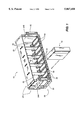
- FIG. 1 shows a perspective front view of the magazine of the present invention
- FIG. 2 shows a perspective rear view of the magazine of the present invention
- FIG. 3 shows a perspective cut-away rear view highlighting details of the rear locking levers
- FIG. 4 is a partial top view of the magazine
- FIGS. 5a and 5b are cross-sectional views of the front spring levers in the closed and open positions, respectively;
- FIGS. 6a and 6b are cross-sectional views of the rear locking levers in the closed and open positions, respectively;
- FIG. 7 is a plan view of the lever assembly
- FIG. 8 is a plan view of bar.
- FIGS. 1-8 show a preferred embodiment of the data storage cartridge magazine according to the present invention.
- Data cartridge magazine 10 (FIG. 1) includes frame 20 comprising a top 22, sidewalls 24a and 24b, a slot floor 58, and left and right handles 30 and 32.
- a bottom cover 26 (FIG. 3) is attached to frame 20 by means of screws (not shown) which extend through screw holes 90 (FIG. 8) in bottom cover 26 and into the underside of slot floor 58.
- the top, sidewalls and slot floor are made of pieces of molded plastic or other rigid material which are fused together.
- the magazine frame has dimensions as appropriate for storing a plurality of cartridges.
- the precise number of such cartridges and the precise dimension of such cartridges depend upon the intended application of the cartridges and the magazine.
- the magazine may be used to hold a plurality of tape media cartridges, such as any of several industry standard 1/2 inch tape cartridges.
- ten storage cartridges are stored in the magazine.
- the approximate dimensions of the frame in the best presently known mode of practicing the invention are therefore: a horizontal length of about 12 inches, a depth of about 3 inches, and a height of about 4 and 1/4 inches from slot floor 58 to top 22.
- the frame further has a series of braces 28 for preventing the frame from being crushed.
- braces are arranged between every other slot and are made of metal.
- the braces are preferably attached to top 22 of the frame by means of tabs 68 (FIG. 4) which are an integral part of the braces.
- Tab recesses 64 have a depth sufficient to accommodate frame tabs 68 so that the tabs are flush with the frame top surface.
- Frame tabs 68 are inserted through tab slots 66 and then twisted to secure the braces.
- the braces are similarly attached to slot floor 58.
- Frame 20 further has left and right handles 30 and 32 for carrying the data storage cartridge magazine.
- the handles extend beyond top 22 and slot floor 58 in order to protect front spring levers 38 (FIG. 4).
- Sidewalls 24a and 24b extend beyond the other side to protect rear locking levers 40.
- the handles are an integral part of sidewalls 24a and 24b but they may alternatively be fused or bolted to the sidewalls.
- the handles are about 3 inches high, but they may alternatively extend the full height of the frame or another distance sufficient to provide a hand grip to the user.
- Frame 20 surrounds a series of horizontally arranged slots 33 (FIG. 1). In the preferred embodiment there are ten slots, but there may be any reasonable number of slots.
- the slots are delineated by lower slot partitions 34 and upper slot partitions 36.
- Slot partitions 34 and 36 are made of plastic and are an integral part of frame 20. Alternatively they may be attached to the frame by any known means such as glued or snapped into position.
- the slot partitions extend substantially the depth of each slot.
- Slot partitions positioned at braces 28 are divided into two separate sections, one on each edge of the partition. The slot partitions are tapered at both ends to facilitate guiding cartridges into slots. Slot floor 58 is also tapered for this reason (FIG. 5a).
- Front spring levers 38 are operated by the user pushing down on them to insert or extract cartridges.
- Each front spring lever 38 has a lip 70 (FIG. 5a) and a front elongated portion 72a (FIG. 7).
- the lip has a number embossed on it for manual identification of the slot. Lip 70 prevents cartridges from sliding out the front of slots 33.
- the front elongated portion 72a is flexible and provides the spring action for the front spring lever.
- the far end of the front elongated portion 72a meets the rear elongated portion 72b of the rear locking lever 40 to form a single piece, the lever assembly 80 (FIG. 7).
- lever assembly 80 On the underside of lever assembly 80 is a ridge 82 which slips into a canal 88 (FIG. 8) formed on bottom cover 26. In this way the lever assembly is easily aligned and attached to bottom cover 26.
- the portion of spring lever 38 extending beyond slot floor 58 is preferably about 1 inch wide and about 1 inch deep.
- the entire lever assembly is preferably made of a single piece of plastic, but other flexible materials could also be used.
- each rear locking lever is operated by a mechanical lever 46 (part of the robotic mechanism within the storage library) which has a finger 48 for engaging and depressing rear locking levers 40.
- a cartridge is then grabbed from a slot by a series of rollers 52a and 52b (also part of the robotic mechanisms of the storage library) which transfer the cartridges to an electronic read/write device in the storage library where it is electronically read or written.
- Each rear locking lever has a lip 41 which is engaged by a mechanical finger 48.
- Each rear locking lever further consists of vertical support fins 74a, 74b and 74c (FIG.
- a rear elongate portion 72b is made of plastic and is flexible to provide the spring action.
- the rear elongated portion meets the front elongated portion (FIG. 7).
- the rear locking levers have a width of about 1/3 inches, i.e. narrower than the front spring levers, and a length of about 1 inch of the portion extending beyond slot floor 58. The height of the lip is about 1/3 inches.
- the rear locking levers are surrounded by ledges 78 (FIG. 4) having dimensions of about 1 inch in length and 1/3 inches in depth. Ledges 78 help guide cartridges into the slots.
- the precise dimensions of the front spring levers and the rear locking levers depend upon the dimensions of the storage cartridges and upon the materials used to form the levers.
- the spring force required to depress the levers to release or insert a cartridge should be high to prevent inadvertent release of a cartridge while low enough to permit easy release or insertion of a cartridge by a human through the front of the magazine.
- One of ordinary skill in the art will determine the dimensions and spring force appropriate for a particular application of the magazine of the present invention.
- Safety bar 44 (FIG. 2) extending substantially the length of frame 20.
- Safety bar 44 is preferably made of metal, is about 10 inches long, 1/16 inches thick and about 1 inch wide. It rests on the top surface of frame bottom 26 (FIG. 6a).
- the safety bar is guided by pegs 96 (FIG. 8) extending from frame bottom 26 through oval-shaped holes 98 in the safety bar.
- the safety bar is kept in the forward and locked position by a spring 84 attached to both ends of the bar. Spring 84 slips over a spring tab 94 cut out of the safety bar.
- the other end of spring 84 is held in place by a spring holding wall 86 which is a raised portion of bottom cover 26.
- Safety bar 44 further has arches 92 cut out of it to provide clearance around screw holes 90.
- a bar disengage slot 54 (FIG. 3) provides access to a mechanical pin (not shown) which pushes the safety bar backward to the unlocked position.
- the bar disengage slot is a notch in bottom cover rear face 27 which measures about 1/2 by 1/2 inches.
- lever travel space 78 (FIG. 6a) and is directly under lever stop 56.
- Bar travel space 78 (FIG. 6a) consists of a notch in bottom cover rear face 27 and being just slightly wider than rear locking lever 40.
- the safety bar In its back or unlocked position the safety bar is completely clear of lever travel space 78 and lever stop 56 (FIG. 6b).
- a user loads data cartridges 42 (FIG. 1) into the data cartridge magazine by pushing down on front spring levers 38 with a finger or with a cartridge.
- Cartridges are pushed into a slot until the user feels the cartridge is stopped by a rear locking lever or until a cartridge is past the lip of the front spring lever 38.
- Cartridges are loosely held in a slot by upper and lower partitions 36 and 34 and front spring lever 38 and rear locking levers 40.
- a user carries magazine 10 by handles 30 and 32. The handles are positioned in the front of the magazine, therefore when it is carried the rear locking levers will be on the downward facing side of the magazine.
- the safety bar insures that the rear locking levers do not become accidently depressed and spill cartridges.
- FIG. 2 shows components within the library subsystem.
- the library includes a mechanical pin (not shown) which is inserted into bar disengage slot 54 (FIG. 3) to push back the safety bar to the unlocked position.
- the mechanical pin inserts in the bar disengage slot 54 to release the lock on the rear locking levers.
- a mechanical finger 28 (FIG. 2), responsive to requests to retrieve a cartridge from a slot or to insert a cartridge into a slot, depresses the now unlocked rear locking lever 40 corresponding to the selected slot into the downward position shown in FIG. 6b.
- a series of rollers 52a and 52b then transfers a cartridge into or out of the slot. After this operation, the finger is withdrawn returning the rear locking lever to its nominal position.
Landscapes
- Automatic Tape Cassette Changers (AREA)
Abstract
Description
Claims (14)
Priority Applications (1)
| Application Number | Priority Date | Filing Date | Title |
|---|---|---|---|
| US08/755,478 US5867458A (en) | 1996-11-22 | 1996-11-22 | Magazine for holding computer data storage cartridges |
Applications Claiming Priority (1)
| Application Number | Priority Date | Filing Date | Title |
|---|---|---|---|
| US08/755,478 US5867458A (en) | 1996-11-22 | 1996-11-22 | Magazine for holding computer data storage cartridges |
Publications (1)
| Publication Number | Publication Date |
|---|---|
| US5867458A true US5867458A (en) | 1999-02-02 |
Family
ID=25039322
Family Applications (1)
| Application Number | Title | Priority Date | Filing Date |
|---|---|---|---|
| US08/755,478 Expired - Fee Related US5867458A (en) | 1996-11-22 | 1996-11-22 | Magazine for holding computer data storage cartridges |
Country Status (1)
| Country | Link |
|---|---|
| US (1) | US5867458A (en) |
Cited By (13)
| Publication number | Priority date | Publication date | Assignee | Title |
|---|---|---|---|---|
| GB2352866A (en) * | 1999-05-25 | 2001-02-07 | Hewlett Packard Co | Media holding device incorporating a media locking mechanism |
| EP1150290A2 (en) * | 2000-04-14 | 2001-10-31 | Hewlett-Packard Company | Apparatus for handling media cartridges |
| US6396658B1 (en) * | 1999-06-18 | 2002-05-28 | Nec Corporation | Media cartridge magazine including structure for latching cartridges inserted into the magazine |
| US6433954B1 (en) * | 1997-04-30 | 2002-08-13 | Spectra Logic Corporation | Tape cartridge holder with misinsertion prevention structure |
| US20030042824A1 (en) * | 2001-08-23 | 2003-03-06 | Coffin Paul Clinton | Removable media storage method and device for a data storage system |
| US6533522B1 (en) * | 1998-06-10 | 2003-03-18 | International Business Machines Corporation | Bi-directional magazine and trays for storage media |
| US6580582B1 (en) * | 1999-09-30 | 2003-06-17 | Quantum Corporation | Cartridge magazine for a tape library |
| US20050056602A1 (en) * | 2003-02-26 | 2005-03-17 | Rtc Industries, Inc. | Merchandise self-facing pusher system |
| US20050195518A1 (en) * | 2004-03-05 | 2005-09-08 | Spectra Logic Corporation | Data Cartridge Library |
| US20090016009A1 (en) * | 2007-04-13 | 2009-01-15 | Data Robotics Incorporated | Carrierless Storage System Enclosure with Ejection Mechanism |
| US20090190252A1 (en) * | 2003-06-26 | 2009-07-30 | Spectra Logic Corporation | Magazine-based data cartridge library |
| US10510372B1 (en) * | 2017-06-02 | 2019-12-17 | Amazon Technologies, Inc. | Mechanical retention and retrieval for tape storage cartridge |
| US20230215463A1 (en) * | 2020-04-29 | 2023-07-06 | Quantum Corporation | Automatic implementation of a physical barrier to protect removable storage media access |
Citations (16)
| Publication number | Priority date | Publication date | Assignee | Title |
|---|---|---|---|---|
| US3565282A (en) * | 1967-12-19 | 1971-02-23 | Staar Sa | Cassette storage magazine |
| US4240551A (en) * | 1977-03-11 | 1980-12-23 | Olympus Optical Co., Ltd. | Magnetic tape cassette holder |
| US4270817A (en) * | 1979-02-23 | 1981-06-02 | Mcrae William P | Cassette storage and dispensing device |
| JPS63293747A (en) * | 1987-05-27 | 1988-11-30 | Nec Corp | Transferring device |
| JPH01178160A (en) * | 1988-01-08 | 1989-07-14 | Nec Corp | Multiple cartridge magnetic tape device |
| US4850485A (en) * | 1987-04-27 | 1989-07-25 | Hitachi, Ltd. | Cartridge magazine |
| JPH03125369A (en) * | 1989-10-11 | 1991-05-28 | Nec Corp | Assembled type magnetic tape device |
| US5021902A (en) * | 1988-02-17 | 1991-06-04 | Hitachi, Ltd. | Tape changer for loading and unloading a magazine of magnetic tape cartridges |
| JPH0410266A (en) * | 1990-04-27 | 1992-01-14 | Hitachi Electron Eng Co Ltd | Recording medium cartridge locking mechanism |
| JPH0512821A (en) * | 1991-07-04 | 1993-01-22 | Hitachi Ltd | Cartridge magazine |
| JPH05109166A (en) * | 1991-10-14 | 1993-04-30 | Nec Corp | Magnetic tape device |
| US5231552A (en) * | 1990-06-29 | 1993-07-27 | Digital Equipment Corporation | Magazine and receiver for media cartridge loader |
| JPH07261871A (en) * | 1994-03-23 | 1995-10-13 | Fujitsu Kiden Ltd | Cartridge unlocking mechanism |
| JPH07272365A (en) * | 1994-04-01 | 1995-10-20 | Aiwa Co Ltd | Automatic loader |
| US5532888A (en) * | 1993-05-27 | 1996-07-02 | International Business Machines Corporation | Cartridge magazine with cartridge processing status indicator |
| US5537268A (en) * | 1994-11-14 | 1996-07-16 | International Business Machine Corporation | Multi-function locking mechanism for a multi-celled data cassette magazine |
-
1996
- 1996-11-22 US US08/755,478 patent/US5867458A/en not_active Expired - Fee Related
Patent Citations (16)
| Publication number | Priority date | Publication date | Assignee | Title |
|---|---|---|---|---|
| US3565282A (en) * | 1967-12-19 | 1971-02-23 | Staar Sa | Cassette storage magazine |
| US4240551A (en) * | 1977-03-11 | 1980-12-23 | Olympus Optical Co., Ltd. | Magnetic tape cassette holder |
| US4270817A (en) * | 1979-02-23 | 1981-06-02 | Mcrae William P | Cassette storage and dispensing device |
| US4850485A (en) * | 1987-04-27 | 1989-07-25 | Hitachi, Ltd. | Cartridge magazine |
| JPS63293747A (en) * | 1987-05-27 | 1988-11-30 | Nec Corp | Transferring device |
| JPH01178160A (en) * | 1988-01-08 | 1989-07-14 | Nec Corp | Multiple cartridge magnetic tape device |
| US5021902A (en) * | 1988-02-17 | 1991-06-04 | Hitachi, Ltd. | Tape changer for loading and unloading a magazine of magnetic tape cartridges |
| JPH03125369A (en) * | 1989-10-11 | 1991-05-28 | Nec Corp | Assembled type magnetic tape device |
| JPH0410266A (en) * | 1990-04-27 | 1992-01-14 | Hitachi Electron Eng Co Ltd | Recording medium cartridge locking mechanism |
| US5231552A (en) * | 1990-06-29 | 1993-07-27 | Digital Equipment Corporation | Magazine and receiver for media cartridge loader |
| JPH0512821A (en) * | 1991-07-04 | 1993-01-22 | Hitachi Ltd | Cartridge magazine |
| JPH05109166A (en) * | 1991-10-14 | 1993-04-30 | Nec Corp | Magnetic tape device |
| US5532888A (en) * | 1993-05-27 | 1996-07-02 | International Business Machines Corporation | Cartridge magazine with cartridge processing status indicator |
| JPH07261871A (en) * | 1994-03-23 | 1995-10-13 | Fujitsu Kiden Ltd | Cartridge unlocking mechanism |
| JPH07272365A (en) * | 1994-04-01 | 1995-10-20 | Aiwa Co Ltd | Automatic loader |
| US5537268A (en) * | 1994-11-14 | 1996-07-16 | International Business Machine Corporation | Multi-function locking mechanism for a multi-celled data cassette magazine |
Cited By (26)
| Publication number | Priority date | Publication date | Assignee | Title |
|---|---|---|---|---|
| US6433954B1 (en) * | 1997-04-30 | 2002-08-13 | Spectra Logic Corporation | Tape cartridge holder with misinsertion prevention structure |
| US6533522B1 (en) * | 1998-06-10 | 2003-03-18 | International Business Machines Corporation | Bi-directional magazine and trays for storage media |
| DE10000121B4 (en) * | 1999-05-25 | 2005-12-08 | Hewlett-Packard Development Co., L.P., Houston | A media holding device including a media locking mechanism |
| GB2352866A (en) * | 1999-05-25 | 2001-02-07 | Hewlett Packard Co | Media holding device incorporating a media locking mechanism |
| GB2352866B (en) * | 1999-05-25 | 2003-03-26 | Hewlett Packard Co | Media holding device incorporating a media locking mechanism |
| US6396658B1 (en) * | 1999-06-18 | 2002-05-28 | Nec Corporation | Media cartridge magazine including structure for latching cartridges inserted into the magazine |
| US6580582B1 (en) * | 1999-09-30 | 2003-06-17 | Quantum Corporation | Cartridge magazine for a tape library |
| EP1150290A2 (en) * | 2000-04-14 | 2001-10-31 | Hewlett-Packard Company | Apparatus for handling media cartridges |
| EP1150290A3 (en) * | 2000-04-14 | 2002-03-20 | Hewlett-Packard Company | Apparatus for handling media cartridges |
| US6480443B1 (en) | 2000-04-14 | 2002-11-12 | Hewlett-Packard Co. | Method and system for restraining a cartridge within an insertable magazine |
| US20030042824A1 (en) * | 2001-08-23 | 2003-03-06 | Coffin Paul Clinton | Removable media storage method and device for a data storage system |
| US7455375B2 (en) | 2001-08-23 | 2008-11-25 | Hewlett-Packard Development Company, L.P. | Removable media storage method and device for a data storage system |
| US7635068B2 (en) * | 2003-02-26 | 2009-12-22 | Rtc Industries, Inc. | Merchandise self-facing pusher system |
| US20050056602A1 (en) * | 2003-02-26 | 2005-03-17 | Rtc Industries, Inc. | Merchandise self-facing pusher system |
| US9997190B2 (en) | 2003-06-26 | 2018-06-12 | Spectra Logic Corporation | Magazine-based data cartridge library |
| US20090190252A1 (en) * | 2003-06-26 | 2009-07-30 | Spectra Logic Corporation | Magazine-based data cartridge library |
| US20100027159A1 (en) * | 2003-06-26 | 2010-02-04 | Spectra Logic Corporation | Magazine-based data cartridge library |
| US8665553B2 (en) | 2003-06-26 | 2014-03-04 | Spectra Logic Corporation | Magazine-based data cartridge library |
| US20050195518A1 (en) * | 2004-03-05 | 2005-09-08 | Spectra Logic Corporation | Data Cartridge Library |
| US7085097B2 (en) | 2004-03-05 | 2006-08-01 | Spectra Logic Corporation | Entry/exit port magazine for a data cartridge library |
| US20090016009A1 (en) * | 2007-04-13 | 2009-01-15 | Data Robotics Incorporated | Carrierless Storage System Enclosure with Ejection Mechanism |
| US8215727B2 (en) | 2007-04-13 | 2012-07-10 | Drobo, Inc. | Carrierless storage system enclosure with ejection mechanism |
| EP2143105B1 (en) * | 2007-04-13 | 2015-02-25 | Data Robotics, Inc. | Carrierless storage system enclosure with ejection mechanism |
| US10510372B1 (en) * | 2017-06-02 | 2019-12-17 | Amazon Technologies, Inc. | Mechanical retention and retrieval for tape storage cartridge |
| US20230215463A1 (en) * | 2020-04-29 | 2023-07-06 | Quantum Corporation | Automatic implementation of a physical barrier to protect removable storage media access |
| US12027182B2 (en) * | 2020-04-29 | 2024-07-02 | Quantum Corporation | Automatic implementation of a physical barrier to protect removable storage media access |
Similar Documents
| Publication | Publication Date | Title |
|---|---|---|
| US5867458A (en) | Magazine for holding computer data storage cartridges | |
| US4702533A (en) | Method and device for storing flat recording media | |
| US5659440A (en) | Data cartridge magazine with interface to automatic cartridge accessing devices | |
| US5576911A (en) | Cartridge locking mechanism and interface | |
| US4457512A (en) | Dealing shoe | |
| US5231552A (en) | Magazine and receiver for media cartridge loader | |
| KR101600118B1 (en) | Dispensing system for items | |
| US6467616B2 (en) | Apparatus for holding a disc-like article | |
| US5537268A (en) | Multi-function locking mechanism for a multi-celled data cassette magazine | |
| US5139321A (en) | Multiple-bin tray assembly for a medical dispensing cassette | |
| US5213209A (en) | One touch drawer type opening and closing device for a compact disc storage case | |
| EP0536785A1 (en) | Multi-stage storage case for cassettes or cassette blocks | |
| US5927834A (en) | Receiver and magazine assembly for storage library system | |
| EP0877363B1 (en) | Data cartridge interlock and release system | |
| US4330162A (en) | Tape cartridge storage device | |
| JPH08227551A (en) | Latch device of cartridge magazine | |
| US4436355A (en) | Modular storage system | |
| US6028733A (en) | Data cartridge caddy-to-storage rack interlock and release system | |
| US4055372A (en) | Storage receptacle for magnetic tape cassette | |
| US5993045A (en) | Data cartridge caddy presence sensing method and apparatus | |
| US4054344A (en) | Storage receptacle for magnetic tape cassette | |
| JP2003532250A (en) | Ejection / storage unit for optical disks, cards, etc. | |
| US5509731A (en) | Ejecting storage case | |
| US5999500A (en) | Data cartridge interlock release actuator system | |
| US6005744A (en) | Storage device for storing magazines of recordable media |
Legal Events
| Date | Code | Title | Description |
|---|---|---|---|
| AS | Assignment |
Owner name: BREECE HILL TECHNOLOGIES, INC., COLORADO Free format text: ASSIGNMENT OF ASSIGNORS INTEREST;ASSIGNORS:BARKLEY, JOHN A.;GRAEBER, STEPHEN WARD;SCHAEFER, ROBERT JOHN;REEL/FRAME:008332/0597 Effective date: 19961121 |
|
| FEPP | Fee payment procedure |
Free format text: PAYOR NUMBER ASSIGNED (ORIGINAL EVENT CODE: ASPN); ENTITY STATUS OF PATENT OWNER: SMALL ENTITY |
|
| AS | Assignment |
Owner name: GREYROCK CAPITAL, A DIVISION OF BANC OF AMERICA CO Free format text: SECURITY AGREEMENT;ASSIGNOR:BREECE HILL TECHNOLOGIES, INC.;REEL/FRAME:010731/0793 Effective date: 20000424 |
|
| FPAY | Fee payment |
Year of fee payment: 4 |
|
| FEPP | Fee payment procedure |
Free format text: PAYER NUMBER DE-ASSIGNED (ORIGINAL EVENT CODE: RMPN); ENTITY STATUS OF PATENT OWNER: SMALL ENTITY Free format text: PAYOR NUMBER ASSIGNED (ORIGINAL EVENT CODE: ASPN); ENTITY STATUS OF PATENT OWNER: SMALL ENTITY |
|
| FEPP | Fee payment procedure |
Free format text: PAYER NUMBER DE-ASSIGNED (ORIGINAL EVENT CODE: RMPN); ENTITY STATUS OF PATENT OWNER: SMALL ENTITY Free format text: PAYOR NUMBER ASSIGNED (ORIGINAL EVENT CODE: ASPN); ENTITY STATUS OF PATENT OWNER: SMALL ENTITY |
|
| FEPP | Fee payment procedure |
Free format text: PAYER NUMBER DE-ASSIGNED (ORIGINAL EVENT CODE: RMPN); ENTITY STATUS OF PATENT OWNER: SMALL ENTITY Free format text: PAYOR NUMBER ASSIGNED (ORIGINAL EVENT CODE: ASPN); ENTITY STATUS OF PATENT OWNER: SMALL ENTITY |
|
| FPAY | Fee payment |
Year of fee payment: 8 |
|
| REMI | Maintenance fee reminder mailed | ||
| LAPS | Lapse for failure to pay maintenance fees | ||
| STCH | Information on status: patent discontinuation |
Free format text: PATENT EXPIRED DUE TO NONPAYMENT OF MAINTENANCE FEES UNDER 37 CFR 1.362 |
|
| FP | Lapsed due to failure to pay maintenance fee |
Effective date: 20110202 |