US5860193A - Top stop for a zipper - Google Patents
Top stop for a zipper Download PDFInfo
- Publication number
- US5860193A US5860193A US09/078,561 US7856198A US5860193A US 5860193 A US5860193 A US 5860193A US 7856198 A US7856198 A US 7856198A US 5860193 A US5860193 A US 5860193A
- Authority
- US
- United States
- Prior art keywords
- stop
- teeth
- slide
- stop block
- row
- Prior art date
- Legal status (The legal status is an assumption and is not a legal conclusion. Google has not performed a legal analysis and makes no representation as to the accuracy of the status listed.)
- Expired - Fee Related
Links
- 238000005192 partition Methods 0.000 claims abstract description 5
- 238000009434 installation Methods 0.000 description 3
Images


Classifications
-
- A—HUMAN NECESSITIES
- A44—HABERDASHERY; JEWELLERY
- A44B—BUTTONS, PINS, BUCKLES, SLIDE FASTENERS, OR THE LIKE
- A44B19/00—Slide fasteners
- A44B19/24—Details
- A44B19/38—Means at the end of stringer by which the slider can be freed from one stringer, e.g. stringers can be completely separated from each other
- A44B19/384—Separable slide fasteners with quick opening devices
- A44B19/386—Top end stop means for quick opening slide fasteners
-
- Y—GENERAL TAGGING OF NEW TECHNOLOGICAL DEVELOPMENTS; GENERAL TAGGING OF CROSS-SECTIONAL TECHNOLOGIES SPANNING OVER SEVERAL SECTIONS OF THE IPC; TECHNICAL SUBJECTS COVERED BY FORMER USPC CROSS-REFERENCE ART COLLECTIONS [XRACs] AND DIGESTS
- Y10—TECHNICAL SUBJECTS COVERED BY FORMER USPC
- Y10T—TECHNICAL SUBJECTS COVERED BY FORMER US CLASSIFICATION
- Y10T24/00—Buckles, buttons, clasps, etc.
- Y10T24/25—Zipper or required component thereof
- Y10T24/2561—Slider having specific configuration, construction, adaptation, or material
- Y10T24/2586—Slider having specific configuration, construction, adaptation, or material including pull tab attaching means
-
- Y—GENERAL TAGGING OF NEW TECHNOLOGICAL DEVELOPMENTS; GENERAL TAGGING OF CROSS-SECTIONAL TECHNOLOGIES SPANNING OVER SEVERAL SECTIONS OF THE IPC; TECHNICAL SUBJECTS COVERED BY FORMER USPC CROSS-REFERENCE ART COLLECTIONS [XRACs] AND DIGESTS
- Y10—TECHNICAL SUBJECTS COVERED BY FORMER USPC
- Y10T—TECHNICAL SUBJECTS COVERED BY FORMER US CLASSIFICATION
- Y10T24/00—Buckles, buttons, clasps, etc.
- Y10T24/25—Zipper or required component thereof
- Y10T24/2593—Zipper or required component thereof including complementary, aligning means attached to ends of interlocking surfaces
-
- Y—GENERAL TAGGING OF NEW TECHNOLOGICAL DEVELOPMENTS; GENERAL TAGGING OF CROSS-SECTIONAL TECHNOLOGIES SPANNING OVER SEVERAL SECTIONS OF THE IPC; TECHNICAL SUBJECTS COVERED BY FORMER USPC CROSS-REFERENCE ART COLLECTIONS [XRACs] AND DIGESTS
- Y10—TECHNICAL SUBJECTS COVERED BY FORMER USPC
- Y10T—TECHNICAL SUBJECTS COVERED BY FORMER US CLASSIFICATION
- Y10T24/00—Buckles, buttons, clasps, etc.
- Y10T24/25—Zipper or required component thereof
- Y10T24/2598—Zipper or required component thereof including means for obstructing movement of slider
Definitions
- the present invention relates to zippers, and more specifically to an improved structure of top stop for a zipper.
- a regular zipper as shown in FIGS. 1 and 2, comprises a top stop at one zipper tape for stoping the slide (not shown) in place.
- the top stop is comprised of an upper stop block and a lower stop block.
- a gap is defined between the upper stop block and the lower stop block.
- the present invention has been accomplished to provide a top stop for a zipper which eliminates the aforesaid drawbacks.
- the upper stop block of the top stop has a front stop face and a rear stop projection. When the slide is pulled upwards to the upper limit position, the rear stop projection and the front stop face are respectively stopped at a top edge of the slide of the zipper and one side of a partition wall inside the slide to prohibit the slide from escaping out of engagement with the row of teeth on the zipper tape.
- the lower stop block has a bottom edge spaced from the row of teeth on the zipper tape at a distance, and a connecting portion downwardly extended from the bottom edge and connected to a top edge of a first tooth of the row of teeth on the zipper tape.
- the lower stop block has a transverse length shorter than the length of the teeth on the zipper tape, and a sloping top edge spaced from a sloping bottom edge of the upper stop block by a gap. Therefore, the lower stop block enables the slide to be conveniently inserted through the gap between the upper stop block and the lower stop block into engagement with the teeth on the zipper tape.
- FIG. 1 is a plain view of a zipper according to the prior art.
- FIG. 2 is a perspective view of the upper stop block of the top stop of the zipper shown in FIG. 1.
- FIG. 3 is a perspective view of the preferred embodiment of the present invention before the installation of the slide.
- FIG. 4 is an anlarged view of a part of FIG. 3, showing the top stop integral with the zipper tape.
- FIG. 5 is a top view of the preferred embodiment of the present invention before the installation of the slide.
- FIG. 6 is similar to FIG. 5, but showing the slide inserted into the gap between the upper stop block and the lower stop block.
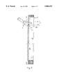
- FIG. 7 is sectional view showing the slide coupled to the teeth on the zipper tape and stopped below the uppper stop block according to the present invention.
- FIG. 8 is a plain view of the present invention, showing the top stop integral with the zipper tape.
- a top stop 1 is injection-molded on a zipper tape 2 at one end of the row of teeth 21 on the zipper tape 2.
- the top stop 1 is comprised of an upper stop block 11, and a lower stop block 12.
- the upper stop block 11 has a sloping bottom edge 111.
- the transverse length of the upper stop block 11 is greater than the length of the teeth 21.
- the lower stop block 12 is spaced between the upper stop block 11 and the row of teeth 21.
- the lower stop block 12 has a bottom edge 122 spaced from the row of teeth 21 at a distance, and a sloping top edge 121 spaced from the sloping bottom edge 111 of the upper stop block 11 by a gap 4.
- the upper stop block 11 has a front stop face 113 at the front side remote from the zipper tape 2, and a rear stop projection 112 at the rear side on the zipper tape 2.
- the rear stop projection 112 of the upper stop block 11 is stopped at a top edge 31 of the slide 3, and the front stop face 113 of the upper stop block 11 is stopped at one side 301 of an inside partition wall 30 of the slide 3, and therefore the slide 3 is stopped from escaping out of the constraint of the top stop 1 (see FIG. 7).
- the lower stop block 12 comprises a connecting portion 120 downwardly extended from the bottom edge 122 and connected to the top edge 211 of the first tooth of the row of teeth 21.
- the lower stop block 12, the connecting portion 120 and the first tooth of the row of teeth 21 are injection-molded on the zipper tape 2 in integrity (see FIG. 4). Because the lower stop block 12, the connecting portion 120 and the first tooth of the row of teeth 21 are integral with the zipper tape 2, fastening the slide 3 to the zipper tape 2 or disconnecting the slide 3 from the zipper tape 2 does not force the lower stop block 12 out of place.
- the transverse length of the lower stop block 12 is shorter than the length of the teeth 21, and the sloping top edge 121 of the lower stop block 12 has both ends smoothly chamfered. Therefore, when the slide 3 is inserted into the gap 4, the partition wall 30 is not hindered in its movement with the slide 3, allowing the slide 3 to be smoothly coupled to the zipper tape 2.
Landscapes
- Slide Fasteners (AREA)
Abstract
A top stop integral with a zipper tape for a zipper, the top stop including an upper stop block having a front stop face and a rear stop projection, the rear stop projection and the front stop face being respectively stopped at a top edge of the slide of the zipper and one side of a partition wall inside the slide to prohibit the slide from escaping out of engagement with the row of teeth on the zipper tape, and a lower stop block having a connecting portion downwardly extended from the bottom edge thereof and connected to a top edge of a first tooth of the row of teeth on the zipper tape.
Description
The present invention relates to zippers, and more specifically to an improved structure of top stop for a zipper.
A regular zipper, as shown in FIGS. 1 and 2, comprises a top stop at one zipper tape for stoping the slide (not shown) in place. The top stop is comprised of an upper stop block and a lower stop block. A gap is defined between the upper stop block and the lower stop block. Through the gap between the upper stop block and the lower stop block, the slide is inserted into engagement with the row of teeth on the zipper tape or pulled outwards and disengaged from the row of teeth. This structure of top stop can not effectively stop the slide from escaping out of engagement with the row of teeth when the slide is pulled to the upper limit position with a high pulling force. Furthermore, when the slide is pulled with a high pulling force, the lower stop block may be driven out of the zipper tape.
The present invention has been accomplished to provide a top stop for a zipper which eliminates the aforesaid drawbacks. According to one aspect of the present invention, the upper stop block of the top stop has a front stop face and a rear stop projection. When the slide is pulled upwards to the upper limit position, the rear stop projection and the front stop face are respectively stopped at a top edge of the slide of the zipper and one side of a partition wall inside the slide to prohibit the slide from escaping out of engagement with the row of teeth on the zipper tape. According to another aspect of the present invention, the lower stop block has a bottom edge spaced from the row of teeth on the zipper tape at a distance, and a connecting portion downwardly extended from the bottom edge and connected to a top edge of a first tooth of the row of teeth on the zipper tape. According to still another aspect of the present invention, the lower stop block has a transverse length shorter than the length of the teeth on the zipper tape, and a sloping top edge spaced from a sloping bottom edge of the upper stop block by a gap. Therefore, the lower stop block enables the slide to be conveniently inserted through the gap between the upper stop block and the lower stop block into engagement with the teeth on the zipper tape.
FIG. 1 is a plain view of a zipper according to the prior art.
FIG. 2 is a perspective view of the upper stop block of the top stop of the zipper shown in FIG. 1.
FIG. 3 is a perspective view of the preferred embodiment of the present invention before the installation of the slide.
FIG. 4 is an anlarged view of a part of FIG. 3, showing the top stop integral with the zipper tape.
FIG. 5 is a top view of the preferred embodiment of the present invention before the installation of the slide.
FIG. 6 is similar to FIG. 5, but showing the slide inserted into the gap between the upper stop block and the lower stop block.
FIG. 7 is sectional view showing the slide coupled to the teeth on the zipper tape and stopped below the uppper stop block according to the present invention.
FIG. 8 is a plain view of the present invention, showing the top stop integral with the zipper tape.
Referring to FIGS. from 3 to 8, a top stop 1 is injection-molded on a zipper tape 2 at one end of the row of teeth 21 on the zipper tape 2. The top stop 1 is comprised of an upper stop block 11, and a lower stop block 12. The upper stop block 11 has a sloping bottom edge 111. The transverse length of the upper stop block 11 is greater than the length of the teeth 21. The lower stop block 12 is spaced between the upper stop block 11 and the row of teeth 21. The lower stop block 12 has a bottom edge 122 spaced from the row of teeth 21 at a distance, and a sloping top edge 121 spaced from the sloping bottom edge 111 of the upper stop block 11 by a gap 4. Through the gap 4 between the sloping bottom edge 111 of the upper stop block 11 and the sloping top edge 121 of the lower stop block 12, a slide 3 is forced into connection with the zipper tape 2 (see FIGS. 5 and 6).
The upper stop block 11 has a front stop face 113 at the front side remote from the zipper tape 2, and a rear stop projection 112 at the rear side on the zipper tape 2. When the slide 3 is pulled to the upper limit position after installation, the rear stop projection 112 of the upper stop block 11 is stopped at a top edge 31 of the slide 3, and the front stop face 113 of the upper stop block 11 is stopped at one side 301 of an inside partition wall 30 of the slide 3, and therefore the slide 3 is stopped from escaping out of the constraint of the top stop 1 (see FIG. 7).
The lower stop block 12 comprises a connecting portion 120 downwardly extended from the bottom edge 122 and connected to the top edge 211 of the first tooth of the row of teeth 21. The lower stop block 12, the connecting portion 120 and the first tooth of the row of teeth 21 are injection-molded on the zipper tape 2 in integrity (see FIG. 4). Because the lower stop block 12, the connecting portion 120 and the first tooth of the row of teeth 21 are integral with the zipper tape 2, fastening the slide 3 to the zipper tape 2 or disconnecting the slide 3 from the zipper tape 2 does not force the lower stop block 12 out of place.
Furthermore, the transverse length of the lower stop block 12 is shorter than the length of the teeth 21, and the sloping top edge 121 of the lower stop block 12 has both ends smoothly chamfered. Therefore, when the slide 3 is inserted into the gap 4, the partition wall 30 is not hindered in its movement with the slide 3, allowing the slide 3 to be smoothly coupled to the zipper tape 2.
Claims (2)
1. A top stop integral with a zipper tape having a row of teeth and slide sliding on said row of teeth, to stop said slide from escaping out of said row of teeth, said top stop comprising an upper stop block having a sloping bottom edge and a transverse length greater than the length of said teeth, and a lower stop block having a bottom edge spaced from said row of teeth at a distance and a sloping top edge spaced from the sloping bottom edge of said upper stop block by a gap, wherein said upper stop block comprises a front stop face at a front side thereof remote from said zipper tape, and a rear stop projection at a rear side thereof integral with said zipper tape, said rear stop projection and said front stop face being respectively stopped at a top edge of said slide and one side of a partition wall inside said slide to prohibit said slide from escaping out of engagement with said row of teeth when said slide is pulled to an upper limit position; said lower stop block comprises a connecting portion downwardly extended from the bottom edge thereof and connected to a top edge of a first tooth of said row of teeth.
2. The top stop of claim 1 wherein said lower stop block has a transverse length shorter than the length of said teeth, and the sloping top edge of said lower stop block has both ends smoothly chamfered.
Priority Applications (1)
| Application Number | Priority Date | Filing Date | Title |
|---|---|---|---|
| US09/078,561 US5860193A (en) | 1998-05-14 | 1998-05-14 | Top stop for a zipper |
Applications Claiming Priority (1)
| Application Number | Priority Date | Filing Date | Title |
|---|---|---|---|
| US09/078,561 US5860193A (en) | 1998-05-14 | 1998-05-14 | Top stop for a zipper |
Publications (1)
| Publication Number | Publication Date |
|---|---|
| US5860193A true US5860193A (en) | 1999-01-19 |
Family
ID=22144819
Family Applications (1)
| Application Number | Title | Priority Date | Filing Date |
|---|---|---|---|
| US09/078,561 Expired - Fee Related US5860193A (en) | 1998-05-14 | 1998-05-14 | Top stop for a zipper |
Country Status (1)
| Country | Link |
|---|---|
| US (1) | US5860193A (en) |
Cited By (8)
| Publication number | Priority date | Publication date | Assignee | Title |
|---|---|---|---|---|
| US6070306A (en) * | 1999-11-19 | 2000-06-06 | Wang; Wallace | Stop and zipper teeth arrangement |
| US6327755B1 (en) * | 2000-06-13 | 2001-12-11 | Wallace Wang | Zipper teeth and top stop arrangement for zipper |
| US6715187B1 (en) * | 2002-11-18 | 2004-04-06 | Wallace Wang | Zip fastener top-end piece arrangement |
| US20090049658A1 (en) * | 2005-04-01 | 2009-02-26 | Ykk Corporation | Readily Burstable Slide Fastener |
| US20120017403A1 (en) * | 2010-07-23 | 2012-01-26 | Tsai-Yu Chang | Stop of a zipper |
| CN106923453A (en) * | 2017-05-12 | 2017-07-07 | 浙江伟星实业发展股份有限公司 | A kind of slide fastener and commodity |
| JPWO2022118376A1 (en) * | 2020-12-01 | 2022-06-09 | ||
| US20230232944A1 (en) * | 2020-06-22 | 2023-07-27 | Ykk Europe Limited | Top stop for slide fastener chain and method of disengaging slider from slide fastener |
Citations (5)
| Publication number | Priority date | Publication date | Assignee | Title |
|---|---|---|---|---|
| USRE18571E (en) * | 1923-03-20 | 1932-08-23 | Wiixiam c | |
| US2573059A (en) * | 1945-08-31 | 1951-10-30 | Conmar Prod Corp | Releasing end stop nonseparable slide fastener |
| US3077651A (en) * | 1961-06-27 | 1963-02-19 | Louis H Morin | Top stop for one-sided separable fasteners |
| US3805339A (en) * | 1970-04-22 | 1974-04-23 | R Howell | Seam type zippers with slider stop member |
| US4023241A (en) * | 1974-12-28 | 1977-05-17 | Yoshida Kogyo Kabushiki Kaisha | Top end construction for slide fasteners |
-
1998
- 1998-05-14 US US09/078,561 patent/US5860193A/en not_active Expired - Fee Related
Patent Citations (5)
| Publication number | Priority date | Publication date | Assignee | Title |
|---|---|---|---|---|
| USRE18571E (en) * | 1923-03-20 | 1932-08-23 | Wiixiam c | |
| US2573059A (en) * | 1945-08-31 | 1951-10-30 | Conmar Prod Corp | Releasing end stop nonseparable slide fastener |
| US3077651A (en) * | 1961-06-27 | 1963-02-19 | Louis H Morin | Top stop for one-sided separable fasteners |
| US3805339A (en) * | 1970-04-22 | 1974-04-23 | R Howell | Seam type zippers with slider stop member |
| US4023241A (en) * | 1974-12-28 | 1977-05-17 | Yoshida Kogyo Kabushiki Kaisha | Top end construction for slide fasteners |
Cited By (13)
| Publication number | Priority date | Publication date | Assignee | Title |
|---|---|---|---|---|
| US6070306A (en) * | 1999-11-19 | 2000-06-06 | Wang; Wallace | Stop and zipper teeth arrangement |
| US6327755B1 (en) * | 2000-06-13 | 2001-12-11 | Wallace Wang | Zipper teeth and top stop arrangement for zipper |
| US6715187B1 (en) * | 2002-11-18 | 2004-04-06 | Wallace Wang | Zip fastener top-end piece arrangement |
| US8925161B2 (en) | 2005-04-01 | 2015-01-06 | Ykk Corporation | Readily burstable slide fastener |
| US8800118B2 (en) * | 2005-04-01 | 2014-08-12 | Ykk Corporation | Readily burstable slide fastener |
| US20090049658A1 (en) * | 2005-04-01 | 2009-02-26 | Ykk Corporation | Readily Burstable Slide Fastener |
| US20120017403A1 (en) * | 2010-07-23 | 2012-01-26 | Tsai-Yu Chang | Stop of a zipper |
| CN106923453A (en) * | 2017-05-12 | 2017-07-07 | 浙江伟星实业发展股份有限公司 | A kind of slide fastener and commodity |
| US20230232944A1 (en) * | 2020-06-22 | 2023-07-27 | Ykk Europe Limited | Top stop for slide fastener chain and method of disengaging slider from slide fastener |
| US12022919B2 (en) * | 2020-06-22 | 2024-07-02 | Ykk Corporation | Top stop for slide fastener chain and method of disengaging slider from slide fastener |
| JPWO2022118376A1 (en) * | 2020-12-01 | 2022-06-09 | ||
| WO2022118376A1 (en) * | 2020-12-01 | 2022-06-09 | Ykk株式会社 | Divided upper-stop |
| CN116456858A (en) * | 2020-12-01 | 2023-07-18 | Ykk株式会社 | Split upper stop |
Similar Documents
| Publication | Publication Date | Title |
|---|---|---|
| KR100993644B1 (en) | Reverse Open Slide Fastener | |
| US5732446A (en) | Metal tie | |
| EP1886592A2 (en) | Slide fastener slider | |
| EP0877849B1 (en) | Pet door assembly | |
| CA1315958C (en) | Buckle assembly | |
| US6615458B2 (en) | Releasable bottom end stop for slide fastener | |
| US5860193A (en) | Top stop for a zipper | |
| ITTO980465A1 (en) | CLOSURE SLIDER FOR ZIPPER | |
| EP0581319B1 (en) | Separable bottom end stop assembly and its assembling and separating method for concealed slide fasteners | |
| JP2002017411A (en) | Zipper cord stopper | |
| US6163941A (en) | Adjustable buckle device | |
| US20180035765A1 (en) | Zipper | |
| JP2004105570A (en) | Slider for hidden slide fastener | |
| US6070306A (en) | Stop and zipper teeth arrangement | |
| JPH08313A (en) | Slide fastener | |
| CN100456985C (en) | Reverse-separating device for slide fastener | |
| US5272793A (en) | Zipper-type closure device | |
| US6715187B1 (en) | Zip fastener top-end piece arrangement | |
| US6327755B1 (en) | Zipper teeth and top stop arrangement for zipper | |
| US5079809A (en) | Anti-binding zipper slider | |
| CN117770584A (en) | Sliders and zippers for invisible zippers | |
| US20020040516A1 (en) | Belt connecting device | |
| US4615082A (en) | Slider for a slide fastener | |
| CN210008600U (en) | Zipper and zipper head thereof | |
| KR200198229Y1 (en) | Zipper |
Legal Events
| Date | Code | Title | Description |
|---|---|---|---|
| FPAY | Fee payment |
Year of fee payment: 4 |
|
| FPAY | Fee payment |
Year of fee payment: 8 |
|
| REMI | Maintenance fee reminder mailed | ||
| LAPS | Lapse for failure to pay maintenance fees | ||
| STCH | Information on status: patent discontinuation |
Free format text: PATENT EXPIRED DUE TO NONPAYMENT OF MAINTENANCE FEES UNDER 37 CFR 1.362 |
|
| FP | Lapsed due to failure to pay maintenance fee |
Effective date: 20110119 |