US5857756A - Lifting and lowering device for furniture elements - Google Patents
Lifting and lowering device for furniture elements Download PDFInfo
- Publication number
- US5857756A US5857756A US08/899,233 US89923397A US5857756A US 5857756 A US5857756 A US 5857756A US 89923397 A US89923397 A US 89923397A US 5857756 A US5857756 A US 5857756A
- Authority
- US
- United States
- Prior art keywords
- furniture element
- base plate
- coupling links
- furniture
- fixing device
- Prior art date
- Legal status (The legal status is an assumption and is not a legal conclusion. Google has not performed a legal analysis and makes no representation as to the accuracy of the status listed.)
- Expired - Fee Related
Links
Images


Classifications
-
- A—HUMAN NECESSITIES
- A47—FURNITURE; DOMESTIC ARTICLES OR APPLIANCES; COFFEE MILLS; SPICE MILLS; SUCTION CLEANERS IN GENERAL
- A47B—TABLES; DESKS; OFFICE FURNITURE; CABINETS; DRAWERS; GENERAL DETAILS OF FURNITURE
- A47B46/00—Cabinets, racks or shelf units, having one or more surfaces adapted to be brought into position for use by extending or pivoting
- A47B46/005—Cabinets, racks or shelf units, having one or more surfaces adapted to be brought into position for use by extending or pivoting by displacement in a vertical plane; by rotating about a horizontal axis
Definitions
- the present invention relates to a furniture assembly comprising a furniture element mounted on a base plate on a vertical wall for movement between an upper position close to the wall and a lower position remote from the wall.
- German patent No. 3,613,530 discloses a cabinet which may be mounted on a vertical wall and whose position may be adjusted between an upper end position close to the wall and a lower end position remote from, and parallel to, the wall.
- at least one guiding device comprised of two guiding elements is affixed to a base plate, the guiding device being arranged on the base plate, on the one hand, and being connected to the cabinet, on the other hand.
- the guiding device is arranged at the side of the movable cabinet and require a side wall which is connected to the base plate.
- Pressure fluid-actuated drives built into the cabinets are used for lifting and lowering the cabinets.
- a furniture assembly comprising a furniture element mounted on a base plate on a vertical wall for movement between an upper position close to the wall and a lower position remote from the wall, the furniture element comprising a device for moving the furniture element between the upper and lower positions, the moving device comprising a drive, pivots fixedly connected to the base plate, coupling links and pivoting elements connecting the coupling links; a device for guiding the furniture element during the movement, the guiding device comprising coupling links and pivots connecting the coupling links of the guiding device to the base plate; and a common fixing device, a pivot fixedly connected to the common fixing device and connected to the moving device, and pivots connecting the coupling links of the guiding device to the common fixing device.
- the moving and guiding devices are hidden to maintain the same optical impression as conventional furniture elements, and they are generally sturdy, free of maintenance requirements and substantially noiseless. They also may be readily installed without excessive costs.
- FIG. 1 is a diagrammatic side view of a furniture assembly according to one embodiment of the invention.
- FIG. 2 is an end view of the embodiment of FIG. 1;
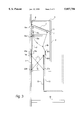
- FIG. 3 is a side view similar to FIG. 1 and showing another embodiment.
- furniture element 2 mounted on base plate 1 on a vertical wall for movement along a path indicated by an arcuate arrow between an upper position close to the wall (shown in full lines) and a lower position remote from the wall (shown in broken lines).
- Furniture element 2 comprises a device for moving the furniture element between the upper and lower positions.
- the moving device comprises drive 5, pivots 4 and 7 fixedly connected to base plate 2, coupling links A and B, and pivoting elements 6, 8 connecting coupling link A to pivot 7 and coupling link B to pivot 17.
- Furniture element 2 further comprises a device for guiding the furniture element during the movement, the guiding device comprising coupling links C and pivots 18 (FIG. 1) and 13 and 22 (FIG. 3) connecting coupling links C to base plate 2.
- Furniture element 2 carries common fixing device 23, and pivot 17 is fixedly connected to the common fixing device and connected to the moving device, and pivots 19 (FIG. 1) and 12 (FIG. 3) connect coupling links C of the guiding device to common fixing device 23.
- Drive 5 for adjusting the position of furniture element 2 may be an electrically, pneumatically or hydraulically operated drive which may be remote-controlled in a conventional manner. It preferably comprises a spindle and is so operated that the spindle is moved up or down in the operating direction.
- Drive 5 is pivoted to base plate 1 at fixed pivot 4 and fixed pivot 7 transmits the driving force by coupling links A, B, pivoting element 8 and pivot 17 to common fixing device 23.
- coupling links A are connected at one end to fixed pivot 7 while their opposite ends are connected to pivoting element 8.
- Coupling links B are connected at one end to pivoting element 8 while their opposite ends are connected to pivot 17 fixedly connected to common fixing device 23 and pivot 17 fixedly connected to base plate 1.
- coupling links C of the guiding device are arranged parallel to each other, and pivots 18 and 19 fixedly connect coupling links C to base plate 1 and common fixing device 23.
- Another coupling link D and pivoting elements 20 connect parallel coupling links C to coupling link D.
- Damping element E is pivoted to base plate 1 at pivot 24 fixedly connected to the base plate and extends between base plate 1 and one of the pivoting elements 20 connecting parallel coupling links C to the other coupling link D.
- a pivoting element 16 connects coupling links C of the guiding device like scissors to each other, pivots 13 and 22 adjustably connecting coupling links C of the guiding device to base plate 1 and pivot 12 fixedly connecting one of the coupling links to common fixing device 23 and another pivot 21 adjustably connecting another one of the coupling links C to the common fixing device.
- base plate 1 has a standard size so that it may be used universally.
- the moving and guiding devices are connected to the base plate and may be economically manufactured so that the entire assembly may be mounted on the wall in a very simple manner.
- the common fixing device constitutes a connection between the moving and guiding devices as well as a means for mounting furniture element 2.
- Pivots 17, and 19 (FIG. 1) and 12 (FIG. 3) fixedly connected to common fixing device 23 connect the moving and guiding devices to the common fixing device and secure move and guide furniture element 2.
- the structure of the movable furniture element need not be changed, the only requirement being the attachment of the common fixing device to the rear wall of the furniture element.
- coupling link A is so pivoted about fixed pivot 7 that point 8a and pivot 17a are moved to position 8b and 17b.
- coupling links C of the guiding device are pivoted to base plate 1 at fixed pivots 18 while pivots 19 move from points 19a to points 19b.
- drive 5 is operated in the same manner as in FIG. 1.
- the guidance of furniture element 2 during its downward movement proceeds in a scissors-like manner.
- Pivot 12 fixedly connected to common fixing device 23 is moved from point 12a to point 12b, forcing pivots 13, 21 and 22, which are guided along guide tracks 14 and 15 to be moved from points 13a, 21a and 22a to points 13b, 21b and 22b.
- Guide track 14 is provided on base plate 1 and guide track 15 is provided on the backside of common fixing device 23.
- the pivotal connection between coupling links C by pivoting element 16 enables the coupling links to move like scissors.
Landscapes
- Legs For Furniture In General (AREA)
- Hinges (AREA)
- Types And Forms Of Lifts (AREA)
- Lift-Guide Devices, And Elevator Ropes And Cables (AREA)
- Warehouses Or Storage Devices (AREA)
Abstract
In a furniture assembly comprising a furniture element mounted on a base plate on a vertical wall for movement between an upper position close to the wall and a lower position remote from the wall, the furniture element comprises a device for moving the furniture element between the upper and lower positions and a guiding device. The moving device comprises a drive, pivots fixedly connected to the base plate, the drive being connected to the pivots, coupling links and pivoting elements connecting the coupling links to the pivots. The guiding device comprises coupling links and pivots connecting the coupling links of the guiding device to the base plate. The moving device is connected to a pivot fixedly connected to a common fixing device, and pivots connect the coupling links of the guiding device to the common fixing device.
Description
1. Field of the Invention
The present invention relates to a furniture assembly comprising a furniture element mounted on a base plate on a vertical wall for movement between an upper position close to the wall and a lower position remote from the wall.
2. Description of the Prior Art
Wall-mounted cabinets which may be lowered are known. For example, German patent No. 3,613,530 discloses a cabinet which may be mounted on a vertical wall and whose position may be adjusted between an upper end position close to the wall and a lower end position remote from, and parallel to, the wall. According to the patent, at least one guiding device comprised of two guiding elements is affixed to a base plate, the guiding device being arranged on the base plate, on the one hand, and being connected to the cabinet, on the other hand.
Other known arrangements comprise guide plates wherebetween guide profiles run in the direction of the movement of the cabinet. Further known guiding devices comprise pairs of elements whose guide arms are connected to the base plate and the cabinet.
All the known systems have in common that the guiding device is arranged at the side of the movable cabinet and require a side wall which is connected to the base plate.
Pressure fluid-actuated drives built into the cabinets are used for lifting and lowering the cabinets.
All the known arrangements have the disadvantage that they restrict the useful space in the movable cabinets. Furthermore, the arrangement of the guiding device on the side of the cabinet has the disadvantage that it requires considerable structural changes of the cabinets.
It is the primary object of this invention to provide a furniture assembly of one or more furniture elements which may be singly or together moved without losing space at the side of the furniture elements or useful space inside the furniture elements.
It is another object of the invention to make it possible to use any type of standard, mass-produced furniture elements as movable furniture elements, without requiring structural changes.
The above and other objects are accomplished according to the present invention with a furniture assembly comprising a furniture element mounted on a base plate on a vertical wall for movement between an upper position close to the wall and a lower position remote from the wall, the furniture element comprising a device for moving the furniture element between the upper and lower positions, the moving device comprising a drive, pivots fixedly connected to the base plate, coupling links and pivoting elements connecting the coupling links; a device for guiding the furniture element during the movement, the guiding device comprising coupling links and pivots connecting the coupling links of the guiding device to the base plate; and a common fixing device, a pivot fixedly connected to the common fixing device and connected to the moving device, and pivots connecting the coupling links of the guiding device to the common fixing device.
The moving and guiding devices are hidden to maintain the same optical impression as conventional furniture elements, and they are generally sturdy, free of maintenance requirements and substantially noiseless. They also may be readily installed without excessive costs.
The above and other objects, advantages and features of this invention will become more apparent from the following detailed description of certain now preferred embodiments thereof, taken in conjunction with the accompanying schematic drawing wherein
FIG. 1 is a diagrammatic side view of a furniture assembly according to one embodiment of the invention;
FIG. 2 is an end view of the embodiment of FIG. 1; and
FIG. 3 is a side view similar to FIG. 1 and showing another embodiment.
Referring now to the drawing, wherein like reference numerals in all figures designate like parts functioning in a like manner, there is shown a furniture assembly comprising furniture element 2 mounted on base plate 1 on a vertical wall for movement along a path indicated by an arcuate arrow between an upper position close to the wall (shown in full lines) and a lower position remote from the wall (shown in broken lines). Furniture element 2 comprises a device for moving the furniture element between the upper and lower positions. The moving device comprises drive 5, pivots 4 and 7 fixedly connected to base plate 2, coupling links A and B, and pivoting elements 6, 8 connecting coupling link A to pivot 7 and coupling link B to pivot 17.
Drive 5 for adjusting the position of furniture element 2 may be an electrically, pneumatically or hydraulically operated drive which may be remote-controlled in a conventional manner. It preferably comprises a spindle and is so operated that the spindle is moved up or down in the operating direction. Drive 5 is pivoted to base plate 1 at fixed pivot 4 and fixed pivot 7 transmits the driving force by coupling links A, B, pivoting element 8 and pivot 17 to common fixing device 23. As shown in the drawing, coupling links A are connected at one end to fixed pivot 7 while their opposite ends are connected to pivoting element 8. Coupling links B are connected at one end to pivoting element 8 while their opposite ends are connected to pivot 17 fixedly connected to common fixing device 23 and pivot 17 fixedly connected to base plate 1.
In the embodiment shown in FIGS. 1 and 2, coupling links C of the guiding device are arranged parallel to each other, and pivots 18 and 19 fixedly connect coupling links C to base plate 1 and common fixing device 23. Another coupling link D and pivoting elements 20 connect parallel coupling links C to coupling link D. Damping element E is pivoted to base plate 1 at pivot 24 fixedly connected to the base plate and extends between base plate 1 and one of the pivoting elements 20 connecting parallel coupling links C to the other coupling link D.
In the embodiment shown in FIG. 3, a pivoting element 16 connects coupling links C of the guiding device like scissors to each other, pivots 13 and 22 adjustably connecting coupling links C of the guiding device to base plate 1 and pivot 12 fixedly connecting one of the coupling links to common fixing device 23 and another pivot 21 adjustably connecting another one of the coupling links C to the common fixing device.
Preferably, base plate 1 has a standard size so that it may be used universally. The moving and guiding devices are connected to the base plate and may be economically manufactured so that the entire assembly may be mounted on the wall in a very simple manner.
The common fixing device constitutes a connection between the moving and guiding devices as well as a means for mounting furniture element 2. Pivots 17, and 19 (FIG. 1) and 12 (FIG. 3) fixedly connected to common fixing device 23 connect the moving and guiding devices to the common fixing device and secure move and guide furniture element 2. The structure of the movable furniture element need not be changed, the only requirement being the attachment of the common fixing device to the rear wall of the furniture element.
As shown in the drawing, another furniture element 3 is fixedly mounted on the wall above furniture element 2 and houses the moving device. This preferred feature makes it possible to use solely the space in the fixed furniture element for mounting the moving device while the entire inside space of the movable furniture element is unencumbered. Fixed furniture element 3 is hard to reach by a handicapped person while the movable furniture element 2 is designed for ready access when in the lowered position.
Referring to the operation of the embodiment of FIGS. 1 and 2, when drive 5 is retracted, coupling link A is so pivoted about fixed pivot 7 that point 8a and pivot 17a are moved to position 8b and 17b. This causes furniture element 2 to move in the path shown by an arcuate arrow in FIG. 1 to move the furniture element from its upper end position adjacent the wall to its lower end position remote from the wall. To guide the furniture element parallel to the wall, coupling links C of the guiding device are pivoted to base plate 1 at fixed pivots 18 while pivots 19 move from points 19a to points 19b.
In the operation of the embodiment of FIG. 3, drive 5 is operated in the same manner as in FIG. 1. The guidance of furniture element 2 during its downward movement proceeds in a scissors-like manner. Pivot 12 fixedly connected to common fixing device 23 is moved from point 12a to point 12b, forcing pivots 13, 21 and 22, which are guided along guide tracks 14 and 15 to be moved from points 13a, 21a and 22a to points 13b, 21b and 22b. Guide track 14 is provided on base plate 1 and guide track 15 is provided on the backside of common fixing device 23. The pivotal connection between coupling links C by pivoting element 16 enables the coupling links to move like scissors.
Claims (8)
1. A furniture assembly comprising
(a) a base plate mounted on a vertical wall,
(b) a furniture element having a rear side facing the vertical wall and being movable between an upper position close to the wall and a lower position remote from the wall,
(c) a device for moving the furniture element between the upper and lower positions,
(d) a device for guiding the furniture element during the movement,
(1) the moving and guiding devices being fixedly connected to the base plate, and
(c) a common fixing device separate from, but connected to, the rear side of the furniture element,
(1) the moving device comprising a drive pivoted to the base plate and coupling links linking the drive to the common fixing device, and
(2) the guiding device comprising coupling links and pivots connecting the coupling links of the guiding device to the base plate and to the common fixing device.
2. The furniture element of claim 1, wherein the coupling links of the guiding device are arranged parallel to each other.
3. The furniture element of claim 2, further comprising another coupling link and pivoting elements connecting the parallel coupling links to the other coupling link.
4. The furniture element of claim 3, further comprising a damping element pivoted to the base plate and extending between the base plate and one of the pivoting elements connecting the parallel coupling links to the other coupling link.
5. The furniture element of claim 1, further comprising a pivoting element connecting the coupling links of the guiding device like scissors to each other, the pivots connecting the coupling links of the guiding device to the base plate and to the common fixing device comprising pivots adjustably connecting the coupling links to the base plate, a pivot fixedly connecting one of the coupling links to the common fixing device and another pivot adjustably connecting another one of the coupling links to the common fixing device.
6. The furniture element of claim 1, wherein the base plate has a standard size.
7. The furniture element of claim 1, wherein the common fixing device constitutes a connection between the moving and guiding devices as well as a means for mounting the furniture element.
8. The furniture assembly of claim 1, further comprising another furniture element fixedly mounted on the wall above the first-named furniture element, the other furniture element housing the moving device.
Priority Applications (4)
| Application Number | Priority Date | Filing Date | Title |
|---|---|---|---|
| DE29500574U DE29500574U1 (en) | 1995-01-16 | 1995-01-16 | Lifting and lowering device for furniture elements |
| DE19517656A DE19517656C2 (en) | 1995-01-16 | 1995-05-13 | Lifting and lowering device for furniture elements |
| EP95109882A EP0722678A3 (en) | 1995-01-16 | 1995-06-24 | Lifting and lowering device for furniture elements |
| US08/899,233 US5857756A (en) | 1995-01-16 | 1997-07-23 | Lifting and lowering device for furniture elements |
Applications Claiming Priority (3)
| Application Number | Priority Date | Filing Date | Title |
|---|---|---|---|
| DE29500574U DE29500574U1 (en) | 1995-01-16 | 1995-01-16 | Lifting and lowering device for furniture elements |
| DE19517656A DE19517656C2 (en) | 1995-01-16 | 1995-05-13 | Lifting and lowering device for furniture elements |
| US08/899,233 US5857756A (en) | 1995-01-16 | 1997-07-23 | Lifting and lowering device for furniture elements |
Publications (1)
| Publication Number | Publication Date |
|---|---|
| US5857756A true US5857756A (en) | 1999-01-12 |
Family
ID=27215120
Family Applications (1)
| Application Number | Title | Priority Date | Filing Date |
|---|---|---|---|
| US08/899,233 Expired - Fee Related US5857756A (en) | 1995-01-16 | 1997-07-23 | Lifting and lowering device for furniture elements |
Country Status (3)
| Country | Link |
|---|---|
| US (1) | US5857756A (en) |
| EP (1) | EP0722678A3 (en) |
| DE (1) | DE29500574U1 (en) |
Cited By (44)
| Publication number | Priority date | Publication date | Assignee | Title |
|---|---|---|---|---|
| US6367898B1 (en) * | 1999-11-19 | 2002-04-09 | Kevin Jobe | Cabinet assembly |
| GB2371470A (en) * | 2000-12-23 | 2002-07-31 | Steadman William D | Movable cupboard |
| US6471311B1 (en) * | 1999-05-25 | 2002-10-29 | David E. Snyder | Cabinet with downward extendable/retractable shelves |
| US20060066189A1 (en) * | 2004-09-30 | 2006-03-30 | Steve Bond | Shelf extending and lifting system |
| US20060192468A1 (en) * | 2005-01-25 | 2006-08-31 | Gardner Stewart E | Fold-down kitchenette |
| US20060238085A1 (en) * | 2005-04-23 | 2006-10-26 | Greenberg Bertram M | Furniture system |
| US20060255701A1 (en) * | 2005-05-13 | 2006-11-16 | Edward Verneuille | Storage cabinet |
| US20070159040A1 (en) * | 2006-01-09 | 2007-07-12 | Fernandez Julio A | Expandable drawer inserts and organizers with hinged trays |
| US7246865B1 (en) | 2003-02-21 | 2007-07-24 | Merrell Ii Rodney K | Overhead storage system |
| US20080182224A1 (en) * | 2007-01-29 | 2008-07-31 | Ahearn David J | Delivery system |
| US20080265727A1 (en) * | 2007-04-25 | 2008-10-30 | Michael Kohlman | Pullout structure for cabinet |
| US20090179538A1 (en) * | 2005-04-23 | 2009-07-16 | Greenberg Bertram M | Method and apparatus for optimizing storage space |
| US20090289535A1 (en) * | 2008-05-23 | 2009-11-26 | Peka-Metall Ag | Cupboard installation part with storage compartments, which part is insertable in an upper cupboard |
| US20100060120A1 (en) * | 2008-09-08 | 2010-03-11 | Mark Van Meter | Wheelchair accessible cabinet apparatus |
| US20100140194A1 (en) * | 2002-08-09 | 2010-06-10 | Joseph Krueger | Storage device with pivot arm |
| US7770986B1 (en) * | 2007-09-20 | 2010-08-10 | Vaidotas Joseph Simaitis | Overhead pull-out swing-down drawer |
| US20110234067A1 (en) * | 2010-03-26 | 2011-09-29 | Richard Antony Vicek | "handy kitchen", pneumatically powered, movable cabinets |
| US20110266937A1 (en) * | 2010-05-03 | 2011-11-03 | Jonathan Roberts | System and Method for an Automatically Adjusting Force Engine and Assisted Storage |
| US8556355B2 (en) | 2005-04-23 | 2013-10-15 | Bertram M. Greenberg | Method and apparatus for optimizing storage space |
| US20140125212A1 (en) * | 2012-11-05 | 2014-05-08 | Lg Electronics Inc. | Refrigerator |
| US8724037B1 (en) * | 2010-06-04 | 2014-05-13 | Kurt William Massey | Mounting system |
| US8777338B2 (en) | 2012-03-27 | 2014-07-15 | Clinton Merle Bunch | Storage system |
| US20140263122A1 (en) * | 2013-03-15 | 2014-09-18 | Jonathan Roberts | System and method for assembling and using assisted storage |
| US20150122758A1 (en) * | 2013-11-06 | 2015-05-07 | Kesseböhmer Holding e.K. | Pull-down shelf for furniture |
| US20160023614A1 (en) * | 2009-04-14 | 2016-01-28 | Newage Products, Inc. | Vehicle mounted lift assembly |
| US20160166058A1 (en) * | 2012-03-27 | 2016-06-16 | Dropout Cabinet Fixtures, Llc | Storage system |
| US20160235194A1 (en) * | 2014-11-06 | 2016-08-18 | Tarek Baranski | Retractable storage system |
| US9625091B1 (en) | 2014-12-06 | 2017-04-18 | Kurt William Massey | Adjustable mounting systems for televisions |
| US9788649B2 (en) | 2012-03-27 | 2017-10-17 | Dropout Cabinet Fixtures, Llc | Storage system |
| US9801465B1 (en) * | 2016-09-28 | 2017-10-31 | John L. Finch, Jr. | Storage systems |
| US10281080B1 (en) | 2010-06-04 | 2019-05-07 | Kurt William Massey | Adjustable mounting systems for televisions |
| US20190357672A1 (en) * | 2018-05-23 | 2019-11-28 | Intelligrated Headquarters, Llc | Reconfigurable carrying devices for material handling |
| US10738941B2 (en) | 2017-09-04 | 2020-08-11 | Manehu Product Alliance, Llc | Display mount assembly |
| US11033107B2 (en) | 2019-07-16 | 2021-06-15 | Francis Douglas Warren | Tilting mounting apparatus |
| US11287080B2 (en) | 2020-02-10 | 2022-03-29 | Manehu Product Alliance, Llc | Multidirectional display mount |
| US11346496B2 (en) | 2018-04-10 | 2022-05-31 | Manehu Product Alliance, Llc | Display mount assembly |
| US20220225843A1 (en) * | 2021-01-21 | 2022-07-21 | Fritz Gerard Eugene | Retractable Wall Mounted Storage Caddy |
| US11684155B2 (en) | 2017-01-27 | 2023-06-27 | 143046 Canada Inc. | Pivotable overhead storage unit |
| US11723457B2 (en) * | 2017-01-27 | 2023-08-15 | 143046 Canada Inc. | Overhead storage unit |
| US11864648B2 (en) | 2019-10-04 | 2024-01-09 | 143046 Canada Inc. | Overhead storage unit with pivoting storage containers |
| US11959583B2 (en) | 2019-12-19 | 2024-04-16 | Manehu Product Alliance, Llc | Adjustable display mounting system |
| US20240237164A1 (en) * | 2022-12-16 | 2024-07-11 | Latoya Danene Reed | Adjustable Microwave Oven Mounting Apparatus |
| US12152720B1 (en) | 2017-04-17 | 2024-11-26 | Manehu Product Alliance, Llc | Adjustable mounting systems for televisions |
| US12295493B2 (en) | 2020-02-08 | 2025-05-13 | Manehu Product Alliance, Llc | Display mounting system with adjustable weight counterbalance |
Families Citing this family (2)
| Publication number | Priority date | Publication date | Assignee | Title |
|---|---|---|---|---|
| DE19923494C1 (en) * | 1999-05-21 | 2001-01-18 | Hermann Droege | Device for easier access to high or low wall cupboards has a parallel lever brace arranged laterally to an insert cupboard part |
| DE102010015004B9 (en) * | 2010-04-14 | 2020-07-23 | Incasa Schlafraumsysteme Gmbh | Cabinet-like furniture |
Citations (14)
| Publication number | Priority date | Publication date | Assignee | Title |
|---|---|---|---|---|
| US1303697A (en) * | 1919-05-13 | Laughlin | ||
| US1434880A (en) * | 1920-04-14 | 1922-11-07 | Frederick J Drysdale | Means for raising and lowering goods |
| US2635030A (en) * | 1950-09-09 | 1953-04-14 | Stebbins | Letdown cabinet |
| US3081138A (en) * | 1961-10-16 | 1963-03-12 | Leo A Stebbins | Lowerable compartment for cabinets |
| US3224827A (en) * | 1963-11-12 | 1965-12-21 | Winco Inc | Cabinet hardware for lowering and retracting a container |
| DE2524407A1 (en) * | 1975-06-03 | 1976-12-16 | Krause Kg Robert | SWIVELING DEVICE FOR A WASTE COLLECTOR |
| US4134629A (en) * | 1976-07-26 | 1979-01-16 | Roger G. Holmes | Pivotable shelving having an associated pivotable door |
| DE3613530A1 (en) * | 1986-01-24 | 1987-07-30 | Wilhelm Apfelbaum | Cupboard and/or table furniture which can be mounted on a vertical wall and the positions of which can be changed in height |
| US4915461A (en) * | 1989-06-07 | 1990-04-10 | Kingsborough Michael R | Storage cabinet retrieval system |
| US5224677A (en) * | 1990-02-23 | 1993-07-06 | Hoyt-Close Products, Inc. | Pull down display and storage apparatus |
| US5228763A (en) * | 1992-03-30 | 1993-07-20 | Lawrence Gingold | Extendable storage element |
| US5249858A (en) * | 1992-05-04 | 1993-10-05 | Nusser Marjorie A | Motor driven movable cabinet |
| JPH0678829A (en) * | 1992-09-01 | 1994-03-22 | Shinkansai Bearing Kk | Ascending/descending device for cabinet |
| WO1994023612A1 (en) * | 1993-04-15 | 1994-10-27 | Jeffrey Richard Hagon | Storage system |
Family Cites Families (1)
| Publication number | Priority date | Publication date | Assignee | Title |
|---|---|---|---|---|
| DE8815589U1 (en) * | 1988-12-15 | 1989-03-02 | Apfelbaum, Wilhelm, 3554 Lohra | Cabinet or similar furniture that can be mounted movably on a vertical wall |
-
1995
- 1995-01-16 DE DE29500574U patent/DE29500574U1/en not_active Expired - Lifetime
- 1995-06-24 EP EP95109882A patent/EP0722678A3/en not_active Withdrawn
-
1997
- 1997-07-23 US US08/899,233 patent/US5857756A/en not_active Expired - Fee Related
Patent Citations (14)
| Publication number | Priority date | Publication date | Assignee | Title |
|---|---|---|---|---|
| US1303697A (en) * | 1919-05-13 | Laughlin | ||
| US1434880A (en) * | 1920-04-14 | 1922-11-07 | Frederick J Drysdale | Means for raising and lowering goods |
| US2635030A (en) * | 1950-09-09 | 1953-04-14 | Stebbins | Letdown cabinet |
| US3081138A (en) * | 1961-10-16 | 1963-03-12 | Leo A Stebbins | Lowerable compartment for cabinets |
| US3224827A (en) * | 1963-11-12 | 1965-12-21 | Winco Inc | Cabinet hardware for lowering and retracting a container |
| DE2524407A1 (en) * | 1975-06-03 | 1976-12-16 | Krause Kg Robert | SWIVELING DEVICE FOR A WASTE COLLECTOR |
| US4134629A (en) * | 1976-07-26 | 1979-01-16 | Roger G. Holmes | Pivotable shelving having an associated pivotable door |
| DE3613530A1 (en) * | 1986-01-24 | 1987-07-30 | Wilhelm Apfelbaum | Cupboard and/or table furniture which can be mounted on a vertical wall and the positions of which can be changed in height |
| US4915461A (en) * | 1989-06-07 | 1990-04-10 | Kingsborough Michael R | Storage cabinet retrieval system |
| US5224677A (en) * | 1990-02-23 | 1993-07-06 | Hoyt-Close Products, Inc. | Pull down display and storage apparatus |
| US5228763A (en) * | 1992-03-30 | 1993-07-20 | Lawrence Gingold | Extendable storage element |
| US5249858A (en) * | 1992-05-04 | 1993-10-05 | Nusser Marjorie A | Motor driven movable cabinet |
| JPH0678829A (en) * | 1992-09-01 | 1994-03-22 | Shinkansai Bearing Kk | Ascending/descending device for cabinet |
| WO1994023612A1 (en) * | 1993-04-15 | 1994-10-27 | Jeffrey Richard Hagon | Storage system |
Cited By (92)
| Publication number | Priority date | Publication date | Assignee | Title |
|---|---|---|---|---|
| US6471311B1 (en) * | 1999-05-25 | 2002-10-29 | David E. Snyder | Cabinet with downward extendable/retractable shelves |
| US6367898B1 (en) * | 1999-11-19 | 2002-04-09 | Kevin Jobe | Cabinet assembly |
| US6752475B2 (en) | 2000-12-23 | 2004-06-22 | William David Steadman | Storage apparatus |
| GB2371470A (en) * | 2000-12-23 | 2002-07-31 | Steadman William D | Movable cupboard |
| GB2371470B (en) * | 2000-12-23 | 2004-04-07 | Steadman William D | Movable storage apparatus |
| US20100140194A1 (en) * | 2002-08-09 | 2010-06-10 | Joseph Krueger | Storage device with pivot arm |
| US8061789B2 (en) * | 2002-08-09 | 2011-11-22 | Joseph Krueger | Storage device with pivot arm |
| US7513580B2 (en) | 2003-02-21 | 2009-04-07 | Merrell Ii Rodney K | Overhead storage system |
| US7246865B1 (en) | 2003-02-21 | 2007-07-24 | Merrell Ii Rodney K | Overhead storage system |
| US20070257584A1 (en) * | 2003-02-21 | 2007-11-08 | Merrell Rodney K Ii | Overhead storage system |
| US20060066189A1 (en) * | 2004-09-30 | 2006-03-30 | Steve Bond | Shelf extending and lifting system |
| US20060192468A1 (en) * | 2005-01-25 | 2006-08-31 | Gardner Stewart E | Fold-down kitchenette |
| US20060238085A1 (en) * | 2005-04-23 | 2006-10-26 | Greenberg Bertram M | Furniture system |
| US8556355B2 (en) | 2005-04-23 | 2013-10-15 | Bertram M. Greenberg | Method and apparatus for optimizing storage space |
| US20090021128A1 (en) * | 2005-04-23 | 2009-01-22 | Bertram Murray Greenberg | Furniture system |
| US20090179538A1 (en) * | 2005-04-23 | 2009-07-16 | Greenberg Bertram M | Method and apparatus for optimizing storage space |
| US8113606B2 (en) | 2005-04-23 | 2012-02-14 | Greenberg Bertram M | Method and apparatus for optimizing storage space |
| US20060255701A1 (en) * | 2005-05-13 | 2006-11-16 | Edward Verneuille | Storage cabinet |
| US20070159040A1 (en) * | 2006-01-09 | 2007-07-12 | Fernandez Julio A | Expandable drawer inserts and organizers with hinged trays |
| US20080182224A1 (en) * | 2007-01-29 | 2008-07-31 | Ahearn David J | Delivery system |
| US7959241B2 (en) * | 2007-04-25 | 2011-06-14 | Kohler Co. | Pullout structure for cabinet |
| US20080265727A1 (en) * | 2007-04-25 | 2008-10-30 | Michael Kohlman | Pullout structure for cabinet |
| CN101686755B (en) * | 2007-04-25 | 2013-12-25 | 科勒公司 | Pullout structure for cabinet |
| US7770986B1 (en) * | 2007-09-20 | 2010-08-10 | Vaidotas Joseph Simaitis | Overhead pull-out swing-down drawer |
| US7922268B2 (en) * | 2008-05-23 | 2011-04-12 | Peka-Metall Ag | Cupboard installation part with storage compartments, which part is insertable in an upper cupboard |
| US20090289535A1 (en) * | 2008-05-23 | 2009-11-26 | Peka-Metall Ag | Cupboard installation part with storage compartments, which part is insertable in an upper cupboard |
| US20100060120A1 (en) * | 2008-09-08 | 2010-03-11 | Mark Van Meter | Wheelchair accessible cabinet apparatus |
| US20160023614A1 (en) * | 2009-04-14 | 2016-01-28 | Newage Products, Inc. | Vehicle mounted lift assembly |
| US20110234067A1 (en) * | 2010-03-26 | 2011-09-29 | Richard Antony Vicek | "handy kitchen", pneumatically powered, movable cabinets |
| US8052230B2 (en) * | 2010-03-26 | 2011-11-08 | Richard Antony Vicek | “Handy kitchen”, pneumatically powered, movable cabinets |
| US20110266937A1 (en) * | 2010-05-03 | 2011-11-03 | Jonathan Roberts | System and Method for an Automatically Adjusting Force Engine and Assisted Storage |
| US9903526B2 (en) * | 2010-05-03 | 2018-02-27 | Jonathan C. Roberts | System and method for an automatically adjusting force engine and assisted storage |
| US12143748B1 (en) | 2010-06-04 | 2024-11-12 | Manehu Product Alliance, Llc | Television mounting systems |
| US11781702B2 (en) | 2010-06-04 | 2023-10-10 | Manehu Product Alliance, Llc | Motorized mounting systems for televisions |
| US12313209B2 (en) | 2010-06-04 | 2025-05-27 | Manehu Product Alliance, Llc | Motorized mounting systems for televisions |
| US12167163B1 (en) | 2010-06-04 | 2024-12-10 | Manehu Product Alliance, Llc | Television mounting systems |
| US12316996B1 (en) | 2010-06-04 | 2025-05-27 | Manehu Product Alliance, Llc | Television mounting systems |
| US11856317B2 (en) | 2010-06-04 | 2023-12-26 | Manehu Product Alliance, Llc | Television mounting systems |
| US8724037B1 (en) * | 2010-06-04 | 2014-05-13 | Kurt William Massey | Mounting system |
| US11849246B1 (en) | 2010-06-04 | 2023-12-19 | Manehu Product Alliance, Llc | Television mounting systems |
| US11781703B2 (en) | 2010-06-04 | 2023-10-10 | Manehu Product Alliance, Llc | Adjustable mounting systems for televisions |
| US20140211100A1 (en) * | 2010-06-04 | 2014-07-31 | Kurt William Massey | Mounting system |
| US11607042B1 (en) | 2010-06-04 | 2023-03-21 | Manehu Product Alliance, Llc | Television mounting systems |
| US11460145B2 (en) | 2010-06-04 | 2022-10-04 | Manehu Product Alliance, Llc | Adjustable mounting systems for televisions |
| US11346493B2 (en) | 2010-06-04 | 2022-05-31 | Manehu Product Alliance, Llc | Motorized mounting systems for televisions |
| US11178354B2 (en) | 2010-06-04 | 2021-11-16 | Manehu Product Alliance, Llc | Methods for installing and using television mounting systems |
| US10277860B2 (en) | 2010-06-04 | 2019-04-30 | Kurt William Massey | Methods for installing and using television mounting systems |
| US10935180B1 (en) | 2010-06-04 | 2021-03-02 | Manehu Product Alliance, Llc | Motorized mounting systems for televisions |
| US9876984B2 (en) * | 2010-06-04 | 2018-01-23 | Kurt William Massey | Mounting system |
| US12388949B1 (en) | 2010-06-04 | 2025-08-12 | Manehu Product Alliance, Llc | Television mounting systems |
| US10281080B1 (en) | 2010-06-04 | 2019-05-07 | Kurt William Massey | Adjustable mounting systems for televisions |
| US10257460B2 (en) * | 2010-06-04 | 2019-04-09 | Kurt William Massey | Mounting system |
| US9788649B2 (en) | 2012-03-27 | 2017-10-17 | Dropout Cabinet Fixtures, Llc | Storage system |
| US8777338B2 (en) | 2012-03-27 | 2014-07-15 | Clinton Merle Bunch | Storage system |
| US9282815B2 (en) * | 2012-03-27 | 2016-03-15 | Dropout Cabinet Fixtures, Llc | Storage system |
| US20160166058A1 (en) * | 2012-03-27 | 2016-06-16 | Dropout Cabinet Fixtures, Llc | Storage system |
| US9629454B2 (en) * | 2012-03-27 | 2017-04-25 | Dropout Cabinet Fixtures, Llc | Storage system |
| US9170043B2 (en) * | 2012-11-05 | 2015-10-27 | Lg Electronics Inc. | Refrigerator |
| US20140125212A1 (en) * | 2012-11-05 | 2014-05-08 | Lg Electronics Inc. | Refrigerator |
| US9464841B2 (en) | 2012-11-05 | 2016-10-11 | Lg Electronics Inc. | Refrigerator |
| US20140263122A1 (en) * | 2013-03-15 | 2014-09-18 | Jonathan Roberts | System and method for assembling and using assisted storage |
| US9980564B2 (en) * | 2013-03-15 | 2018-05-29 | Jonathan Roberts | System and method for assembling and using assisted storage |
| US9055813B2 (en) * | 2013-11-06 | 2015-06-16 | Kesseböhmer Holding e.K. | Pull-down shelf for furniture |
| US20150122758A1 (en) * | 2013-11-06 | 2015-05-07 | Kesseböhmer Holding e.K. | Pull-down shelf for furniture |
| US20160235194A1 (en) * | 2014-11-06 | 2016-08-18 | Tarek Baranski | Retractable storage system |
| US9510675B2 (en) * | 2014-11-06 | 2016-12-06 | Tarek Baranski | Retractable storage system |
| US9625091B1 (en) | 2014-12-06 | 2017-04-18 | Kurt William Massey | Adjustable mounting systems for televisions |
| US9801465B1 (en) * | 2016-09-28 | 2017-10-31 | John L. Finch, Jr. | Storage systems |
| US11684155B2 (en) | 2017-01-27 | 2023-06-27 | 143046 Canada Inc. | Pivotable overhead storage unit |
| US11723457B2 (en) * | 2017-01-27 | 2023-08-15 | 143046 Canada Inc. | Overhead storage unit |
| US12152720B1 (en) | 2017-04-17 | 2024-11-26 | Manehu Product Alliance, Llc | Adjustable mounting systems for televisions |
| US12228236B1 (en) | 2017-04-17 | 2025-02-18 | Manehu Product Alliance, Llc | Adjustable mounting systems for televisions |
| US12455041B2 (en) | 2017-09-04 | 2025-10-28 | Manehu Product Alliance, Llc | Display mount assembly |
| US11668434B2 (en) | 2017-09-04 | 2023-06-06 | Manehu Product Alliance, Llc | Display mount assembly |
| US10738941B2 (en) | 2017-09-04 | 2020-08-11 | Manehu Product Alliance, Llc | Display mount assembly |
| US12152725B2 (en) | 2017-09-04 | 2024-11-26 | Manehu Product Alliance, Llc | Display mount assembly |
| US11346496B2 (en) | 2018-04-10 | 2022-05-31 | Manehu Product Alliance, Llc | Display mount assembly |
| US12372195B2 (en) | 2018-04-10 | 2025-07-29 | Manehu Product Alliance, Llc | Display mount assembly |
| US11774033B2 (en) | 2018-04-10 | 2023-10-03 | Manehu Product Alliance, Llc | Display mount assembly |
| US10729236B2 (en) * | 2018-05-23 | 2020-08-04 | Intelligrated Headquarters, Llc | Reconfigurable carrying devices for material handling |
| US20190357672A1 (en) * | 2018-05-23 | 2019-11-28 | Intelligrated Headquarters, Llc | Reconfigurable carrying devices for material handling |
| US11033107B2 (en) | 2019-07-16 | 2021-06-15 | Francis Douglas Warren | Tilting mounting apparatus |
| US11864648B2 (en) | 2019-10-04 | 2024-01-09 | 143046 Canada Inc. | Overhead storage unit with pivoting storage containers |
| US11959583B2 (en) | 2019-12-19 | 2024-04-16 | Manehu Product Alliance, Llc | Adjustable display mounting system |
| US12295493B2 (en) | 2020-02-08 | 2025-05-13 | Manehu Product Alliance, Llc | Display mounting system with adjustable weight counterbalance |
| US11287080B2 (en) | 2020-02-10 | 2022-03-29 | Manehu Product Alliance, Llc | Multidirectional display mount |
| US12372194B2 (en) | 2020-02-10 | 2025-07-29 | Manehu Product Alliance, Llc | Multidirectional display mount |
| US11802653B2 (en) | 2020-02-10 | 2023-10-31 | Manehu Product Alliance, Llc | Multidirectional display mount |
| US12114818B2 (en) * | 2021-01-21 | 2024-10-15 | Fritz Gerard Eugene | Retractable wall mounted storage caddy |
| US20220225843A1 (en) * | 2021-01-21 | 2022-07-21 | Fritz Gerard Eugene | Retractable Wall Mounted Storage Caddy |
| US20240237164A1 (en) * | 2022-12-16 | 2024-07-11 | Latoya Danene Reed | Adjustable Microwave Oven Mounting Apparatus |
| US12439485B2 (en) * | 2022-12-16 | 2025-10-07 | Latoya Danene Reed | Adjustable microwave oven mounting apparatus |
Also Published As
| Publication number | Publication date |
|---|---|
| DE29500574U1 (en) | 1995-04-06 |
| EP0722678A2 (en) | 1996-07-24 |
| EP0722678A3 (en) | 1997-05-21 |
Similar Documents
| Publication | Publication Date | Title |
|---|---|---|
| US5857756A (en) | Lifting and lowering device for furniture elements | |
| EP4137659B1 (en) | Door assembly and storage cabinet | |
| DE69720377D1 (en) | Pull strips for doors | |
| CA2135344A1 (en) | Door drive equipment for mass transit vehicle | |
| AU4454989A (en) | Door assembly including a movable door with a flexible door panel | |
| AU2002227501A1 (en) | Counterbalance system cable drum for sectional doors | |
| JPS58131284A (en) | Slide door operating apparatus | |
| US4322912A (en) | Safety device for a vehicle door actuated by a turnable shaft | |
| AU645027B2 (en) | Door with several sliding leaves | |
| EP0968349B2 (en) | A vent | |
| GB2227789A (en) | Bi-parting shutter system | |
| JPH07314375A (en) | Robot hand floating unit | |
| WO1996029472A3 (en) | Roadway barrier | |
| WO1994027017A1 (en) | Opening and closing device for door | |
| CA2182107A1 (en) | Fume hood with improved counterbalance system | |
| EP0798473A3 (en) | Linear actuator provided with limit microswitches having a very simple adjustment | |
| DE50008373D1 (en) | goal | |
| ATE247763T1 (en) | ACTUATING DEVICE FOR DOOR OR WINDOW CONSTRUCTIONS WITH SWIVELING WING ELEMENTS | |
| MX9700031A (en) | Hydraulic spring crusher. | |
| EP1736630B1 (en) | Retractable safety edge mechanism, installation method and resultant door system | |
| DE59201548D1 (en) | Espagnolette fitting for windows, doors or the like | |
| CA2295352A1 (en) | Locking device for a door system | |
| EP0781892A3 (en) | Automatic sliding door with at least one wing | |
| ITMI941918A1 (en) | GOALKEEPER STOP, IN PARTICULAR FOR CARS | |
| CA2045544A1 (en) | Retractable dome structure and method |
Legal Events
| Date | Code | Title | Description |
|---|---|---|---|
| REMI | Maintenance fee reminder mailed | ||
| LAPS | Lapse for failure to pay maintenance fees | ||
| STCH | Information on status: patent discontinuation |
Free format text: PATENT EXPIRED DUE TO NONPAYMENT OF MAINTENANCE FEES UNDER 37 CFR 1.362 |
|
| FP | Lapsed due to failure to pay maintenance fee |
Effective date: 20030112 |