US5852797A - Secure electronic chronometry device - Google Patents

Secure electronic chronometry device Download PDF

Info

Publication number
US5852797A
US5852797A US08/891,329 US89132997A US5852797A US 5852797 A US5852797 A US 5852797A US 89132997 A US89132997 A US 89132997A US 5852797 A US5852797 A US 5852797A
Authority
US
United States
Prior art keywords
processing unit
data
time data
interface
unit
Prior art date
Legal status (The legal status is an assumption and is not a legal conclusion. Google has not performed a legal analysis and makes no representation as to the accuracy of the status listed.)
Expired - Fee Related
Application number
US08/891,329
Inventor
Jean-Pierre Bovay
Silvio Chianese
Current Assignee (The listed assignees may be inaccurate. Google has not performed a legal analysis and makes no representation or warranty as to the accuracy of the list.)
Omega Electronics SA
Original Assignee
Omega Electronics SA
Priority date (The priority date is an assumption and is not a legal conclusion. Google has not performed a legal analysis and makes no representation as to the accuracy of the date listed.)
Filing date
Publication date
Application filed by Omega Electronics SA filed Critical Omega Electronics SA
Assigned to OMEGA ELECTRONICS S.A. reassignment OMEGA ELECTRONICS S.A. ASSIGNMENT OF ASSIGNORS INTEREST (SEE DOCUMENT FOR DETAILS). Assignors: BOVAY, JEAN-PIERRE, CHIANESE, SILVIO
Application granted granted Critical
Publication of US5852797A publication Critical patent/US5852797A/en
Anticipated expiration legal-status Critical
Expired - Fee Related legal-status Critical Current

Links

Images

Classifications

    • GPHYSICS
    • G04HOROLOGY
    • G04FTIME-INTERVAL MEASURING
    • G04F10/00Apparatus for measuring unknown time intervals by electric means
    • G04F10/04Apparatus for measuring unknown time intervals by electric means by counting pulses or half-cycles of an ac
    • GPHYSICS
    • G07CHECKING-DEVICES
    • G07CTIME OR ATTENDANCE REGISTERS; REGISTERING OR INDICATING THE WORKING OF MACHINES; GENERATING RANDOM NUMBERS; VOTING OR LOTTERY APPARATUS; ARRANGEMENTS, SYSTEMS OR APPARATUS FOR CHECKING NOT PROVIDED FOR ELSEWHERE
    • G07C1/00Registering, indicating or recording the time of events or elapsed time, e.g. time-recorders for work people
    • G07C1/22Registering, indicating or recording the time of events or elapsed time, e.g. time-recorders for work people in connection with sports or games

Definitions

  • the present invention concerns an electronic chronometry device for measuring the time obtained by participants during sport events, and more specifically such a device which is associated to an information processing system so as to improve the processing of data as well as the presentation of the results thus obtained.
  • Sports chronometry is usually performed using an electronic chronograph printer.
  • These apparatus consists of a timepiece base, of a counter, of memory storing means comprising the events' journal, of a calculation and a chornographic information processing unit, of a display and of a printer.
  • These apparatus are connected to time sensors by way of input interfaces and to information media by way of output inferfaces.
  • These apparatus may be provided with interchangeable application modules which are dedicated to different sports. This technique guarantees an efficient security for all the recorded and calculated times.
  • an object of the present invention is to remedy these defaults by presenting an electronic chronometry device for time measurements which is very flexible and which allows an improved visual representation of the results, but which is nevertheless completely protected from manipulations which could corrupt the chronometrical data and the events journal comprising these data.
  • the invention has as object an electronic chronometry device comprising:
  • an acquisition cell arranged to receive time data coming from at least one time events measuring sensor
  • a storing unit for storing said time data
  • a processing unit for processing said time data and which is associated with said acquisition cell said device being characterized in that said storing unit is associated with an interface which is arranged in such a way as to allow said processing unit to access said storing unit and to read certain of said time data which are stored in said storing unit without allowing a modification of said storing unit by said processing unit.
  • the device according to the invention thus allows to protect the data coming from the closed world of sports chronometry for communication with the open environment of the information world so as to improve and to facilitate the visualisation of the results.
  • FIG. 1 represents schematically the electronic chronometry device according to the invention
  • FIG. 2 shows in more detail the device of FIG. 1;
  • FIG. 3 represents schematically a function-time diagram of the device according to the invention.
  • FIG. 1 shows schematically an electronic chronometry device according to the invention designated by the general reference D.
  • Device D comprises an acquisition cell 2 of time data which can communicate by way of an interface 1 with a processing unit 4 of these data, this unit 4 may a programmable unit, for example a microcomputer or a PC.
  • Interface 1 allows the dialogue between the acquisition cell 2 and the data processing unit 4 as will be explained in more detail hereafter.
  • acquisition cell 2 corresponds to that of a classical electronic chronograph and is thus to acquire the times coming from the different chronometry sensors 8 during a sports event 7.
  • acquisition cell 2 comprises, in a manner known as such, a data input interface and a data output interface (non-represented), a timebase (non-represented), a storing unit which is called the events journal 9 for memorising the time data 6 coming from sensors 8 which are arranged so as to detect the sports event 7 which takes place, an output buffer memory and a pilot printer (non-represented) recording all chronographic pulses provided by sensors 8 in real time and in chronological order before any processing.
  • Processing unit 4 is in itself incapable of performing the chronometry of a sports competition. This unit is associated by way of a classical connection, for example a bidirectional RS-232 cable, to acquisition cell 2 for allowing a desired presentation and/or visualisation.
  • a classical connection for example a bidirectional RS-232 cable
  • An operator of processing unit 4 may send for example by way of a keyboard 13, commands or instructions to acquisition cell 2 to instruct it to transmit the time data which is necessary to calculate the race time and needed for the desired visualisation.
  • an application program which is dedicated to a certain sport to be commanded by processing unit 4.
  • This program may be arranged in such a way as to manage a dialogue between cell 2 and processing unit or PC 4 and to prepare the received time data 6 for the intended visualisation.
  • processing unit 4 is not directly connected to acquisition cell 2, but by way of interface
  • interface 1 allows the dialogue between processing unit 4 and acquisition cell 2, and more precisely between this unit 4 and the storing unit or events journal 9.
  • interface 1 is arranged in such a way as to allow a certain level of authorisation access to data stored in the journal 9 so as to avoid that a non-authorised third may read and/or copy these time data 6.
  • This interface thus ensures a locking of the information, and this interface may be obtained for example by way of a protection software which requires a password before releasing the transfer of time data 6 from acquisition cell 2 towards processing unit 4.
  • a protection software which requires a password before releasing the transfer of time data 6 from acquisition cell 2 towards processing unit 4.
  • the interrogation of the journal 9 by the processing unit is authorised.
  • no modification at all of the journal 9 is allowed, only a reading authorisation of the journal may be provided by interface 1.
  • processing unit 4 is constituted by way of a programmable computer which is arranged in such a way as to load an operating software into acquisition cell 2, this software being dependent on the sports event 7 which is to monitored by interface 1.
  • This operation software may be used to manage the way of storing the different time data 6 received from sensors 8 in predetermined places or memories of storing unit 9.
  • the adaptation of acquisition cell 2 to the event 7 to be monitored may be facilitated thanks to an operation software dedicated to this event.
  • FIG. 3 shows schematically a function-time diagram of device D.
  • the vertical axis of FIG. 3 represents the time starting at an instant t 0
  • the horizontal axis shows the different instructions and time data which pass through the different components of the device D according to the invention.
  • processing unit 4 may send an instruction 15 comprising a password, or an identification code, to interface 1 for establishing the dialogue with acquisition cell 2 and, possibly, for then allowing the charging of an operation software for acquisition cell 2 so as to initialise this cell 2 and to start the chronometry.
  • processing unit 4 further comprises a monitor or screen 18 on which the different operations are visualised. Acquisition cell 2 is thus ready to transmit the time data 6 towards processing unit 4.
  • Instruction 15 may also comprise an order from the operator for sending only certain time data 6 which are intended for the desired calculation.
  • the first of the time data 6, the one which corresponds to the departure instant, comes from sensor 8 and is captured by acquisition cell 2.
  • This data is stored in storing unit 9 and is printed on the pilot printer, non-represented.
  • interface 1 establishes a connection between cell 2 and processing unit 4, this data 6 is immediately transmitted, at instant t i to processing unit 4 which visualies it on its screen 18. From that moment on, this received data is considered valid and it is available for any successive processing by the operator of processing unit 4.
  • a parasite data 19 is captured by sensor 8.
  • This data 19 may for example be created by a referee or a bird passing in front of the sensor. Naturally, this passage is detected in a normal manner and the time data is transmitted towards processing unit 4.
  • This parasite data 19 is also visualised on screen 18 and stored in the events journal 9 for a control of all the detected data. However, this data will not be accepted as being a valid data according to the used operation system which normal only accepts data received within a predetermined time window. Parasite data 19 is thus not available for a processing by the operator, but it is possible to allow for an a-posteriori validation of such a data if this data turns out to be correct afterall. Such processing and/or validation of the parasite data is known to the skilled person and will not be described in further detail here.
  • a second parasite data 19 is also visualised on screen 18 and stored in the journal 9, but it is not taken into consideration either if it does not arrive within the allowed time and it is thus also not available within processing unit 4.
  • the operator may send, also in a manner known as such, an cancellation instruction 20 to interface 1 to invalid the reception of this parasite data 19 and to ask interface 1 to transmit the next data which it has received.
  • This data (d 21 in FIG. 3, arrives at instant t i+4 in interface 1 and is thus transmitted towards programmable unit 4, where it is visualised on screen 18 and taken into consideration by processing unit 4 for the calculation of the race time.
  • This calculation result, referenced 22 in FIG. 3 is then sent towards the outer world which may be an information data network.

Abstract

The electronic chronometry device (D) comprises an acquisition cell (2) arranged to receive time data (6) coming from at least one time events measurement sensor (8), a storing unit (9) for storing said time data (6), and a processing unit (4) of said time data (6) and associated with said acquisition cell (2). This device is characterized in that said storing unit (9) is associated with an interface (1) which is arranged so as to allow said processing unit (4) to access said storing unit (9) and to read certain of said time data (6) stored in said storing unit (9) without allowing modification of said storing unit (9) by said processing unit (4).

Description

The present invention concerns an electronic chronometry device for measuring the time obtained by participants during sportive events, and more specifically such a device which is associated to an information processing system so as to improve the processing of data as well as the presentation of the results thus obtained.
Sports chronometry is usually performed using an electronic chronograph printer. These apparatus consists of a timepiece base, of a counter, of memory storing means comprising the events' journal, of a calculation and a chornographic information processing unit, of a display and of a printer. These apparatus are connected to time sensors by way of input interfaces and to information media by way of output inferfaces. These apparatus may be provided with interchangeable application modules which are dedicated to different sports. This technique guarantees an efficient security for all the recorded and calculated times.
On the contrary, this technique is limited by its application flexibility, by the global vision of the sports events which is to be controlled and by the operation power, despite the interchangeable application modules which remain static and which are difficult to reprogram, which is harmful to the flexibility.
Electronic chronometry devices are already known which are connected to microcomputer such as a PC acting as the data processor, see for example the document FR-A-2 698 987. Thus, it is possible to work with alphanumerical information for establishing departure lists, results lists and statistical lists. It is further possible to modify the results as a function of weighing factors which are defined by the rules of the competition.
However, such devices cannot operate in real time, which is an important limitation with respect to the direct information which is demanded by the media and the sportsmen. Furthermore, these devices are neither economical, nor optimally managed, because they require an operator for each apparatus.
To overcome these inconveniences, two solutions have already been proposed. On the one hand, it is possible to integrate the chronometric program into the computer itself, which then becomes a full measurement apparatus, and on the other hand, it is possible to integrate the computer circuit into a chronometry apparatus. However, in these two cases, besides the specific inconveniences due to the evolution of information technology and to the material adaptment in the field, the measured times are no longer protected against exterior aggressions on the measurement system. Indeed, as soon as a chronometric information is stored even momentarily in a RAM, this information is vulnerable, despite the presence of coding means. A chronometrical data is easily modified across an information network or with a cunning operator.
Thus an object of the present invention is to remedy these defaults by presenting an electronic chronometry device for time measurements which is very flexible and which allows an improved visual representation of the results, but which is nevertheless completely protected from manipulations which could corrupt the chronometrical data and the events journal comprising these data.
To this effect, the invention has as object an electronic chronometry device comprising:
an acquisition cell arranged to receive time data coming from at least one time events measuring sensor,
a storing unit for storing said time data, and
a processing unit for processing said time data and which is associated with said acquisition cell, said device being characterized in that said storing unit is associated with an interface which is arranged in such a way as to allow said processing unit to access said storing unit and to read certain of said time data which are stored in said storing unit without allowing a modification of said storing unit by said processing unit.
Thanks to this intelligent interface, the device according to the invention thus allows to protect the data coming from the closed world of sports chronometry for communication with the open environment of the information world so as to improve and to facilitate the visualisation of the results.
An embodiment of the object of the invention will be described hereafter by way of example only by referring to the attached drawings in which:
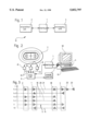
FIG. 1 represents schematically the electronic chronometry device according to the invention;
FIG. 2 shows in more detail the device of FIG. 1; and
FIG. 3 represents schematically a function-time diagram of the device according to the invention.
FIG. 1 shows schematically an electronic chronometry device according to the invention designated by the general reference D. Device D comprises an acquisition cell 2 of time data which can communicate by way of an interface 1 with a processing unit 4 of these data, this unit 4 may a programmable unit, for example a microcomputer or a PC. Interface 1 allows the dialogue between the acquisition cell 2 and the data processing unit 4 as will be explained in more detail hereafter.
Reference will now be made to FIG. 2. The role of the acquisition cell 2 corresponds to that of a classical electronic chronograph and is thus to acquire the times coming from the different chronometry sensors 8 during a sports event 7. To this effect, acquisition cell 2 comprises, in a manner known as such, a data input interface and a data output interface (non-represented), a timebase (non-represented), a storing unit which is called the events journal 9 for memorising the time data 6 coming from sensors 8 which are arranged so as to detect the sports event 7 which takes place, an output buffer memory and a pilot printer (non-represented) recording all chronographic pulses provided by sensors 8 in real time and in chronological order before any processing.
Processing unit 4 is in itself incapable of performing the chronometry of a sports competition. This unit is associated by way of a classical connection, for example a bidirectional RS-232 cable, to acquisition cell 2 for allowing a desired presentation and/or visualisation.
An operator of processing unit 4 may send for example by way of a keyboard 13, commands or instructions to acquisition cell 2 to instruct it to transmit the time data which is necessary to calculate the race time and needed for the desired visualisation.
Advantageously, there is provided an application program which is dedicated to a certain sport to be commanded by processing unit 4. This program may be arranged in such a way as to manage a dialogue between cell 2 and processing unit or PC 4 and to prepare the received time data 6 for the intended visualisation.
According to the invention, it is possible to protect the time data 6 coming from sensors 8 from external influences which might corrupt the chronologic information. This is why processing unit 4 is not directly connected to acquisition cell 2, but by way of interface
Indeed, interface 1 allows the dialogue between processing unit 4 and acquisition cell 2, and more precisely between this unit 4 and the storing unit or events journal 9. To this effect, interface 1 is arranged in such a way as to allow a certain level of authorisation access to data stored in the journal 9 so as to avoid that a non-authorised third may read and/or copy these time data 6. This interface thus ensures a locking of the information, and this interface may be obtained for example by way of a protection software which requires a password before releasing the transfer of time data 6 from acquisition cell 2 towards processing unit 4. Each time that interface 1 receives a correct password from processing unit 4, the interrogation of the journal 9 by the processing unit is authorised. According to the invention, no modification at all of the journal 9 is allowed, only a reading authorisation of the journal may be provided by interface 1.
Preferably, processing unit 4 is constituted by way of a programmable computer which is arranged in such a way as to load an operating software into acquisition cell 2, this software being dependent on the sports event 7 which is to monitored by interface 1. This operation software may be used to manage the way of storing the different time data 6 received from sensors 8 in predetermined places or memories of storing unit 9. Thus, the adaptation of acquisition cell 2 to the event 7 to be monitored may be facilitated thanks to an operation software dedicated to this event.
The functioning of the chronometric device D according to the invention will be explained hereafter with the help of FIG. 3 which shows schematically a function-time diagram of device D.
The vertical axis of FIG. 3 represents the time starting at an instant t0, and the horizontal axis shows the different instructions and time data which pass through the different components of the device D according to the invention.
Firstly, the operator of processing unit 4 may send an instruction 15 comprising a password, or an identification code, to interface 1 for establishing the dialogue with acquisition cell 2 and, possibly, for then allowing the charging of an operation software for acquisition cell 2 so as to initialise this cell 2 and to start the chronometry. In a way which is known as such, processing unit 4 further comprises a monitor or screen 18 on which the different operations are visualised. Acquisition cell 2 is thus ready to transmit the time data 6 towards processing unit 4. Instruction 15 may also comprise an order from the operator for sending only certain time data 6 which are intended for the desired calculation.
At instant ti, the first of the time data 6, the one which corresponds to the departure instant, comes from sensor 8 and is captured by acquisition cell 2. This data is stored in storing unit 9 and is printed on the pilot printer, non-represented. As interface 1 establishes a connection between cell 2 and processing unit 4, this data 6 is immediately transmitted, at instant ti to processing unit 4 which visualies it on its screen 18. From that moment on, this received data is considered valid and it is available for any successive processing by the operator of processing unit 4.
Then, at instant ti+1, a parasite data 19 is captured by sensor 8. This data 19 may for example be created by a referee or a bird passing in front of the sensor. Naturally, this passage is detected in a normal manner and the time data is transmitted towards processing unit 4. This parasite data 19 is also visualised on screen 18 and stored in the events journal 9 for a control of all the detected data. However, this data will not be accepted as being a valid data according to the used operation system which normal only accepts data received within a predetermined time window. Parasite data 19 is thus not available for a processing by the operator, but it is possible to allow for an a-posteriori validation of such a data if this data turns out to be correct afterall. Such processing and/or validation of the parasite data is known to the skilled person and will not be described in further detail here.
At instant ti+2, a second parasite data 19 is also visualised on screen 18 and stored in the journal 9, but it is not taken into consideration either if it does not arrive within the allowed time and it is thus also not available within processing unit 4.
Thus, at instant ti+3, the operator may send, also in a manner known as such, an cancellation instruction 20 to interface 1 to invalid the reception of this parasite data 19 and to ask interface 1 to transmit the next data which it has received. This data, referenced 21 in FIG. 3, arrives at instant ti+4 in interface 1 and is thus transmitted towards programmable unit 4, where it is visualised on screen 18 and taken into consideration by processing unit 4 for the calculation of the race time. This calculation result, referenced 22 in FIG. 3, is then sent towards the outer world which may be an information data network.
It may thus be understood that the data are stored in a storing unit, or events journal 9, and are printed before any processing. Any successive processing can only modify the presentation of the visualisation of this data, but it cannot modify the journal 9 itself, because this journal 9 has a limited authorization access. Acquisition cell 2 cannot classify or process the data itself, this being managed by the operation software which has been loaded before hand by processing unit 4.
Thanks to the separation of processing unit 4 and of storing unit or event journal 9 and thanks to the limited access of the latter, an instruction 23 coming from the outside network can in no case alter this journal 9 of interface 1 due to an insufficient authorization of access and because it has no possibility to modify the content of the storing unit.
Naturally, the electronic chronometry device which is described hereabove may undergo several modifications and may be presented in other embodiments which are obvious to the skilled person without departing from the scope of the present invention.

Claims (3)

What is claimed is:
1. An electronic chronometry device comprising an acquisition cell arranged to receive time data coming from at least one time events measuring sensor, a storing unit for storing said time data, and a processing unit for processing said time data and which is associated with said acquisition cell,
wherein said storage unit is associated with an interface which is arranged in such a way as to allow said processing unit to access said storage unit and to read certain of said time data which are stored in said storage unit without allowing modification of said storage unit by said processing unit.
2. The chronometry device according to claim 1, wherein said acquisition cell is arranged in such a way that it may receive a specific predetermined program for managing the storing of said time data in said storage unit.
3. The chronometry device according to claim 2, wherein said processing unit is arranged in such a way as to allow the loading of said program in said acquisition cell after having been allowed access by said interface.
US08/891,329 1996-07-11 1997-07-10 Secure electronic chronometry device Expired - Fee Related US5852797A (en)

Applications Claiming Priority (2)

Application Number Priority Date Filing Date Title
CH1741/96 1996-07-11
CH01741/96A CH691011A5 (en) 1996-07-11 1996-07-11 The electronic timing.

Publications (1)

Publication Number Publication Date
US5852797A true US5852797A (en) 1998-12-22

Family

ID=4217502

Family Applications (1)

Application Number Title Priority Date Filing Date
US08/891,329 Expired - Fee Related US5852797A (en) 1996-07-11 1997-07-10 Secure electronic chronometry device

Country Status (4)

Country Link
US (1) US5852797A (en)
AU (1) AU716104B2 (en)
CA (1) CA2210067C (en)
CH (1) CH691011A5 (en)

Cited By (1)

* Cited by examiner, † Cited by third party
Publication number Priority date Publication date Assignee Title
US9922377B2 (en) 2015-03-23 2018-03-20 Wiedza Creations LLC Electronic timekeeping system and method of using same

Citations (7)

* Cited by examiner, † Cited by third party
Publication number Priority date Publication date Assignee Title
US3781529A (en) * 1972-05-25 1973-12-25 R Mcconnell Digital timing system
US4142680A (en) * 1977-03-21 1979-03-06 Oswald Robert A High resolution timing recording system
GB1592442A (en) * 1978-01-24 1981-07-08 Grand Prix Of America Inc Timing system
US4451896A (en) * 1980-07-14 1984-05-29 Universite Laval Electronic chronometer
FR2698987A1 (en) * 1992-12-08 1994-06-10 Deyna Daniel Electronic timer and scorer for equestrian jumping events - uses microprocessor to handle timing and interaction with scorer, and also transmission and display of results
FR2725633A1 (en) * 1994-10-17 1996-04-19 Millier Roger Jules Simultaneous timing and scoring of equestrian jumping events
US5526290A (en) * 1993-08-04 1996-06-11 Casio Computer Co., Ltd. Pace calculation devices

Patent Citations (7)

* Cited by examiner, † Cited by third party
Publication number Priority date Publication date Assignee Title
US3781529A (en) * 1972-05-25 1973-12-25 R Mcconnell Digital timing system
US4142680A (en) * 1977-03-21 1979-03-06 Oswald Robert A High resolution timing recording system
GB1592442A (en) * 1978-01-24 1981-07-08 Grand Prix Of America Inc Timing system
US4451896A (en) * 1980-07-14 1984-05-29 Universite Laval Electronic chronometer
FR2698987A1 (en) * 1992-12-08 1994-06-10 Deyna Daniel Electronic timer and scorer for equestrian jumping events - uses microprocessor to handle timing and interaction with scorer, and also transmission and display of results
US5526290A (en) * 1993-08-04 1996-06-11 Casio Computer Co., Ltd. Pace calculation devices
FR2725633A1 (en) * 1994-10-17 1996-04-19 Millier Roger Jules Simultaneous timing and scoring of equestrian jumping events

Non-Patent Citations (4)

* Cited by examiner, † Cited by third party
Title
Journal Suisse D Horlogerie et de Bijouterie, No. 1, Dec. 1984, Lausanne Ch, p. 4 XP002029252 Chronometres intelligentS . *
Journal Suisse D'Horlogerie et de Bijouterie, No. 1, Dec. 1984, Lausanne Ch, p. 4 XP002029252 "Chronometres <<intelligentS>>".
Uhren Juwelen Schmuck, No. 1, 20 Jan. 1981, Bielefeld De, p. 42, XP002029253 "Das Zeitmesssystem der alpinen Skiwettkampfe".
Uhren Juwelen Schmuck, No. 1, 20 Jan. 1981, Bielefeld De, p. 42, XP002029253 Das Zeitmesssystem der alpinen Skiwettkampfe . *

Cited By (2)

* Cited by examiner, † Cited by third party
Publication number Priority date Publication date Assignee Title
US9922377B2 (en) 2015-03-23 2018-03-20 Wiedza Creations LLC Electronic timekeeping system and method of using same
US10867357B2 (en) 2015-03-23 2020-12-15 Wiedza Creations LLC Electronic timekeeping system and method of using same

Also Published As

Publication number Publication date
AU2852797A (en) 1998-01-22
CH691011A5 (en) 2001-03-30
CA2210067A1 (en) 1998-01-11
AU716104B2 (en) 2000-02-17
CA2210067C (en) 2004-11-02

Similar Documents

Publication Publication Date Title
US4369442A (en) Code controlled microcontroller readout from coin operated machine
CA2180237C (en) Method and apparatus for detecting fraud or theft in a gaming machine
US6570498B1 (en) Integrated access system
CA2010365C (en) Storage system with adjacent lockers controlled by a microprocessor device
US5469363A (en) Electronic tag with source certification capability
US4626984A (en) Remote computer control for irrigation systems
EP0498034B1 (en) System for monitoring a combustion apparatus
WO1993019428A1 (en) Gaming device providing high security communications with a remote station
EP1316814A1 (en) Tracing of transponder-tagged objects
US5224707A (en) Security system for a gaming device
KR960700783A (en) GAME HOUSE SYSTEM UTILIZING STORAGE MEDIUM
CA2421770A1 (en) Integrated security system
GB2068615A (en) Cash accounting and surveillance system for games
JPS62502143A (en) intelligent radiation monitor
US6667764B1 (en) Video camera apparatus and video monitor system
US3787670A (en) Automatic diagnostic system
US5852797A (en) Secure electronic chronometry device
US4571698A (en) Apparatus and system for remote timing of plural entities
GB2256396A (en) Monitoring faults in postage meter systems.
BR112013031154B1 (en) METHOD AND SYSTEM FOR CONTROLLING THE INTEGRITY OF ONE OR MULTIPLE CARGO CONTAINERS
CA1292580C (en) Process control equipment for use in adverse environments
CA2050064C (en) Mine system
CN107144332A (en) A kind of True k Scale Weighing System and method based on instrument long-distance automatic clear
US6693560B2 (en) Submarine mast autonomous controller and method
KR101930508B1 (en) 3d blueprint offering system for construction and architecture using qr code

Legal Events

Date Code Title Description
AS Assignment

Owner name: OMEGA ELECTRONICS S.A., SWITZERLAND

Free format text: ASSIGNMENT OF ASSIGNORS INTEREST;ASSIGNORS:BOVAY, JEAN-PIERRE;CHIANESE, SILVIO;REEL/FRAME:008689/0451

Effective date: 19970630

FEPP Fee payment procedure

Free format text: PAYOR NUMBER ASSIGNED (ORIGINAL EVENT CODE: ASPN); ENTITY STATUS OF PATENT OWNER: LARGE ENTITY

FPAY Fee payment

Year of fee payment: 4

FPAY Fee payment

Year of fee payment: 8

REMI Maintenance fee reminder mailed
LAPS Lapse for failure to pay maintenance fees
STCH Information on status: patent discontinuation

Free format text: PATENT EXPIRED DUE TO NONPAYMENT OF MAINTENANCE FEES UNDER 37 CFR 1.362

FP Lapsed due to failure to pay maintenance fee

Effective date: 20101222